Generator Overhaul Delphi CS-144 KG9
Disassembly Procedure
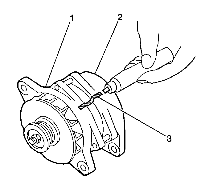
- Make scribe marks (3)
on the following components to ensure correct alignment during assembly:
| • | The drive end frame (1). |
| • | The slip ring end frame (2). |
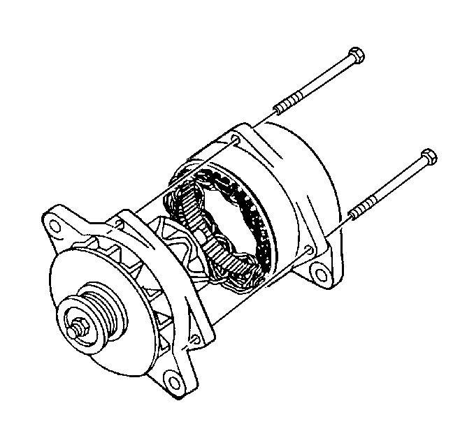
- Remove the 4 through bolts.
- Separate the slip ring end frame and the drive end frame.
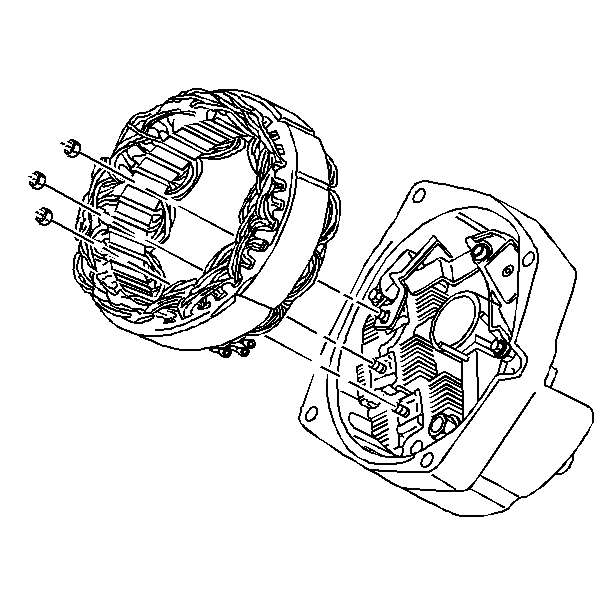
- Remove the stator lead
attaching nuts.
- Remove the stator from the slip ring end frame.
- Inspect the stator. Refer to step 1 in Inspection Procedure.
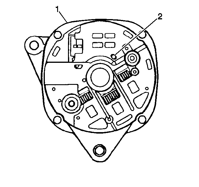
- Tap the plastic dust shield
retaining pin (2) inward just enough for the retaining clips to release.
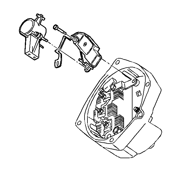
- Remove the brush holder
screw.
- Remove the voltage regulator insulated screw.
- Remove the voltage regulator and the brush holder with the dust
shield from the slip ring end frame as a unit.
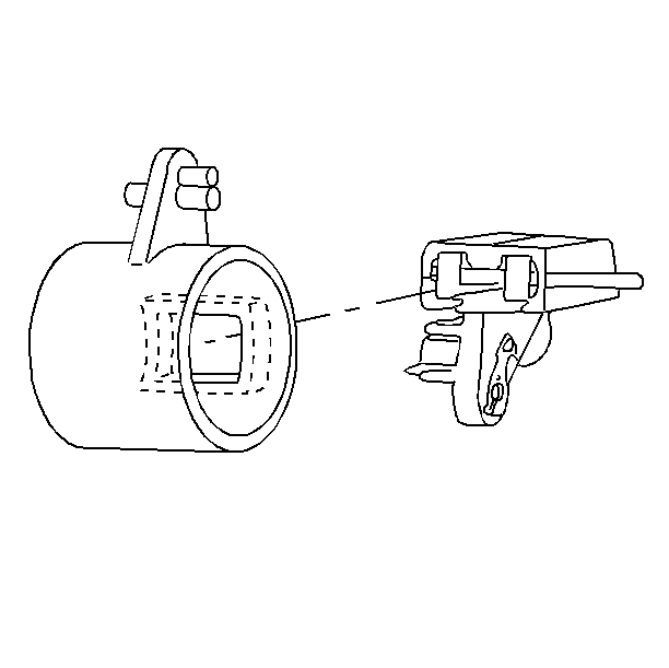
- Remove the dust shield
from the brush holder. The brushes and springs will be loose inside.
- Inspect the brush holder assembly. Refer to step 4.3 in Inspection
Procedure.
Do the following:
| 12.1. | Clean the brushes with a dry soft cloth. |
| 12.2. | Place the springs into the brush holder. |
| 12.3. | Turn each brush so that the wire aligns with the slot in the brush
holder and push each brush into the holder. Make sure the wires are looped
loosely and are not pinched or kinked. Install a nonmetallic pin through
the holes in the brush holder to hold the brushes in a retracted position
for later reassembly. |
Notice: Avoid excessive heat during the soldering and unsoldering procedures. Excessive
heat will damage the voltage regulator.
- Inspect the voltage regulator. Refer to step 4.4 in Inspection Procedure.
If necessary, disassemble the voltage regulator, the brush holder and the
connector strap assembly.
In order to disassemble the components :
| • | Unsolder the connector clips between the voltage regulator and
the brush holder, and between the voltage regulator and the connector strap. |
| • | Disassemble the parts while the solder is still soft. |
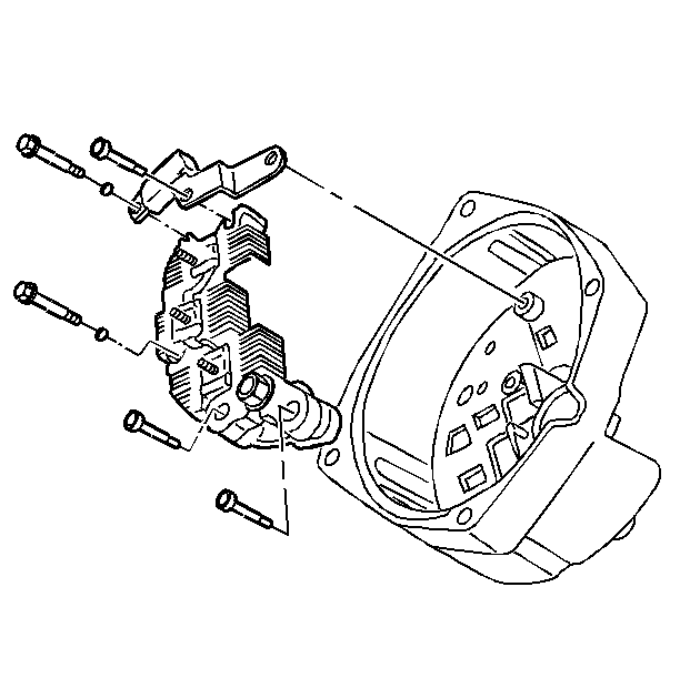
- Inspect the slip ring
end assembly. Refer to step 4 in Inspection Procedure. If necessary remove
the capacitor and the rectifier bridge.
| • | Remove the rectifier bridge. |
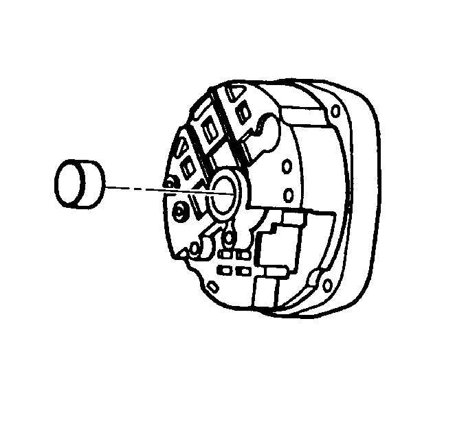
- Inspect the slip ring
end bearing. If the bearing is dry or damaged, replace the bearing. Remove
the slip ring end bearing only if necessary.
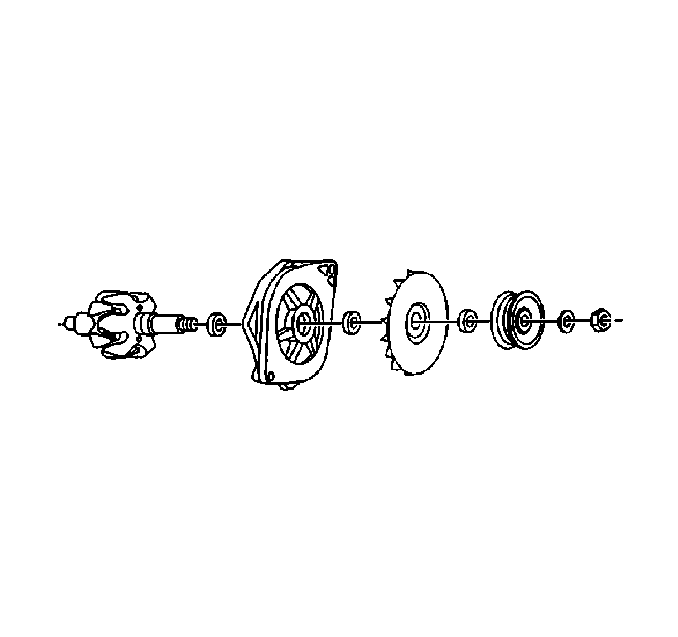
- Inspect the drive end
assembly. Refer to step 2 in Inspection Procedure. If necessary, disassemble
the drive end assembly by removing the following parts from the drive end
frame:
- Remove the inside collar from the rotor.
Inspection Procedure
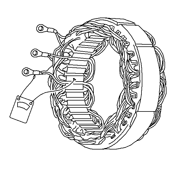
- Inspect the stator.
| 1.1. | Visually inspect the stator windings: |
| • | Replace the stator if some coils of wire are darker than others
and appear to have overheated. |
| • | Inspect the 3 phase connections. There are two wires attached
to each connector. Replace the stator if any of the wires are loose or broken. |
| • | Replace the stator if any of the stator windings are damaged. |
| 1.2. | Inspect the stator for grounds with a digital multimeter or continuity
check. Replace the stator if the windings are grounded to the stator frame. |
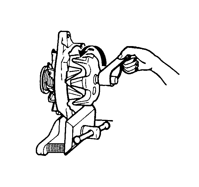
- Inspect the drive end
assembly.
| 2.1. | Inspect the drive end bearing by spinning the rotor by hand. If
the rotor does not spin freely, has a rough feel, or is noisy, replace the
drive end frame. Refer to step 16 in Disassembly Procedure. |
| 2.2. | Inspect the slip rings on the rotor. |
| 2.2.1. | If the slip rings are rough or dirty, spin the rotor while holding
a 400 grain polishing cloth around the rings. |
Blow away all the copper dust.
| 2.2.2. | Replace the rotor if the slip rings are damaged or cannot be cleaned
to a smooth condition. Refer to step 16 in Disassembly Procedure. |
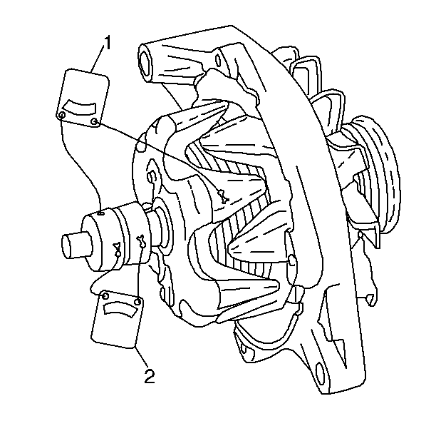
- Inspect the rotor windings
with a digital multimeter.
| • | The rotor windings should not be grounded (1). |
| • | The rotor windings should not be an open circuit (2). |
| | Important: The rotor resistance will vary for different generator models.
|
| • | The resistance (2) should be between 2.1-2.4 ohms at room temperature. |
| • | Replace the rotor if the windings are grounded, open or have incorrect
resistance. Refer to step 16 in Disassembly Procedure. |
- Inspect the slip ring
end assembly.
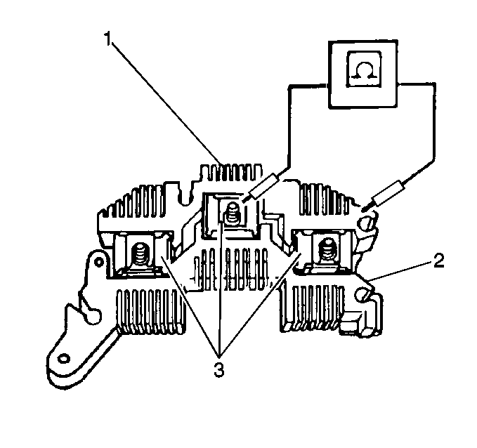
| 4.1. | Inspect the diodes in the rectifier bridge with a digital multimeter. |
| 4.1.1. | There should be continuity in one direction between each of the
3 phase clips (3) and the grounded heat sink (1). When the polarity of the
digital multimeter is reversed, all three readings should show open circuits.
All three diode readings should be close to each other. |
| 4.1.2. | There should be continuity in one direction between each of the
3 phase clips (1) and the positive heat sink (2). When the polarity of the
digital multimeter is reversed, all three readings should show open circuits.
All three diode readings should be close to each other. |
Replace the rectifier bridge when one or more of the readings do not
follow this pattern. Refer to step 14 in Disassembly Procedure.
| 4.2. | Inspect the slip ring end bearing. Replace the bearing if the
bearing is dry or damaged. |
| 4.3. | Inspect the brush holder assembly. |
| 4.3.1. | Replace the brush holder assembly if the brushes are damaged or
broken. Replace the brush holder assembly if the brushes are worn to less
than 10 mm (0.4 in) in length. Refer to steps 7 through 11
in Disassembly Procedure. |
| 4.3.2. | Replace the brush springs if the springs are damaged or broken. |
| 4.4. | Replace the voltage regulator if no other problems are found that
can cause an existing high, low or no output condition. Refer to step 13 in
Disassembly Procedure. |
Assembly Procedure

- Install the inside collar
into the rotor.
- Install the rotor into the drive end frame.
Notice: Use the correct fastener in the correct location. Replacement fasteners
must be the correct part number for that application. Fasteners requiring
replacement or fasteners requiring the use of thread locking compound or sealant
are identified in the service procedure. Do not use paints, lubricants, or
corrosion inhibitors on fasteners or fastener joint surfaces unless specified.
These coatings affect fastener torque and joint clamping force and may damage
the fastener. Use the correct tightening sequence and specifications when
installing fasteners in order to avoid damage to parts and systems.
- Install the following
components onto the rotor shaft:
| • | The generator shaft nut |
Tighten
Tighten the generator shaft nut to 100 N·m (74 lb ft).

- Install the bearing into
the slip ring end frame from the outside, until the bearing is flush with
the outside shoulder of the slip ring end frame. Use tooling to make sure
that force is applied to the outer bearing race only.
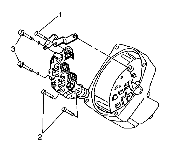
Important: In order to ensure proper operation of the unit, install the slip ring
end frame components in the correct order.
- Install the rectifier bridge.
Important: Install the capacitor with the insulator material resting against the
drive end frame.
- Install the capacitor.
Important: Make sure that the insulated bolt, located at the capacitor/rectifier
bridge, attaches the capacitor strap and the rectifier bridge to the slip
ring end frame. Make sure that the metal side of the capacitor strap is
against the regulator connection.
- Install the bolts.
Tighten
Tighten the bolts to 2.5 N·m (22 lb in).

- Install the brushes into
the brush holder with the retaining pin.
Notice: Avoid excessive heat during the soldering and unsoldering procedures. Excessive
heat will damage the voltage regulator.
- Install the connector strap and the brush holder onto the regulator.
Make sure the solder clips fit snugly. Solder the clips in place.
- Install the dust shield onto the brush holder.

- Install the voltage regulator,
the brush holder, the dust shield, and the connector strap assembly into the
slip ring end frame as one unit.
- Tap the plastic retaining pin on the dust shield into the retaining
clip until flush with the outside of the housing. Make sure that the brush
retaining pin goes through the access hole to the outside of the slip ring
end frame for removal after the generator is assembled.
- Install the insulated regulator bolt.
Tighten
Tighten the insulated regulator bolt to 2.5 N·m (22 lb in).
- Install the brush holder bolt.
Tighten
Tighten the brush holder bolt to 2.5 N·m (22 lb in).

- Place the stator terminals
over the rectifier bridge terminals in order to assemble the stator.
- Install the stator lead nuts.
Tighten
Tighten the stator lead nuts to 2.5 N·m (22 lb in).

- Assemble the slip ring
(2) and drive end (1) frames. Note the scribe marks (3).
- Install the through bolts.
Tighten
Tighten the through bolts to 8 N·m (71 lb in).
- Remove the retaining pin in order to release the brushes against
the slip rings.
Generator Overhaul Generator Pulley Valeo K68
Removal Procedure
The only serviceable parts on the Valeo A13VI+ generator are the pulley,
the voltage regulator/brush kit and the generator rear cover.
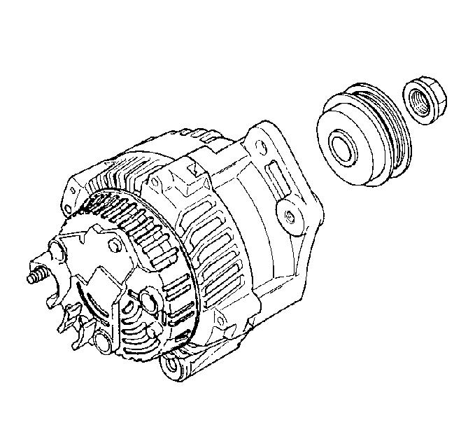
- Remove the rotor shaft
drive end nut.
- Remove the generator pulley washer.
- Remove the generator pulley.
Installation Procedure

- Install the generator
pulley to the generator.
- Install the generator pulley washer.
Notice: Use the correct fastener in the correct location. Replacement fasteners
must be the correct part number for that application. Fasteners requiring
replacement or fasteners requiring the use of thread locking compound or sealant
are identified in the service procedure. Do not use paints, lubricants, or
corrosion inhibitors on fasteners or fastener joint surfaces unless specified.
These coatings affect fastener torque and joint clamping force and may damage
the fastener. Use the correct tightening sequence and specifications when
installing fasteners in order to avoid damage to parts and systems.
- Install the generator
rotor shaft drive end nut.
Tighten
Tighten the generator rotor shaft drive end nut to 70 N·m
(52 lb ft).
Generator Overhaul Rear Cover Valeo K68
Removal Procedure
The only serviceable parts on the Valeo A13VI+ generator are the pulley,
the voltage regulator/brush kit and the generator rear cover.
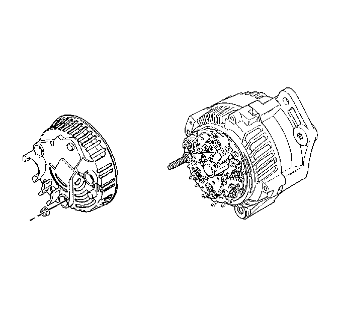
- Remove the generator rear
cover nuts.
- Remove the generator rear cover.
Installation Procedure

- Install the generator
rear cover.
Notice: Use the correct fastener in the correct location. Replacement fasteners
must be the correct part number for that application. Fasteners requiring
replacement or fasteners requiring the use of thread locking compound or sealant
are identified in the service procedure. Do not use paints, lubricants, or
corrosion inhibitors on fasteners or fastener joint surfaces unless specified.
These coatings affect fastener torque and joint clamping force and may damage
the fastener. Use the correct tightening sequence and specifications when
installing fasteners in order to avoid damage to parts and systems.
- Install the generator
rear cover nuts.
Tighten
Tighten the generator rear cover nuts to 2 N·m (18 lb in).
Generator Overhaul Regulator/Brush Holder Valeo K68
Removal Procedure
The only serviceable parts on the Valeo A13VI+ generator are the pulley,
the voltage regulator/brush kit and the generator rear cover.
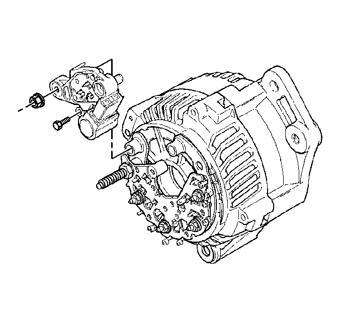
- Refer to Handling ESD Sensitive Parts Notice
in General Information.
Remove the generator rear cover. Refer to
Generator Overhaul
.
- Remove the generator regulator/brush holder nuts.
- Remove the silicon from the generator regulator terminals.
- Remove the generator regulator terminal bolts/screws.
- Remove the generator regulator/brush holder from the generator.
Installation Procedure

- install the generator
regulator/brush holder to the generator.
Notice: Use the correct fastener in the correct location. Replacement fasteners
must be the correct part number for that application. Fasteners requiring
replacement or fasteners requiring the use of thread locking compound or sealant
are identified in the service procedure. Do not use paints, lubricants, or
corrosion inhibitors on fasteners or fastener joint surfaces unless specified.
These coatings affect fastener torque and joint clamping force and may damage
the fastener. Use the correct tightening sequence and specifications when
installing fasteners in order to avoid damage to parts and systems.
- Install the generator
regulator terminal screws.
Tighten
Tighten the generator regulator terminal screws to 2 N·m
(18 lb in).
- Install the generator regulator/brush holder nuts.
Tighten
Tighten the generator regulator/brush holder nuts to 3 N·m
(27 lb in).
- Install the new brush cover. Remove the temporary brush cover
and insert the new brush cover.
- Apply high temperature silicon GM P/N 1052915 or equivalent, to
the voltage regulator terminals.
- Install the generator rear cover. Refer to
Generator Overhaul
.


