Tools Required
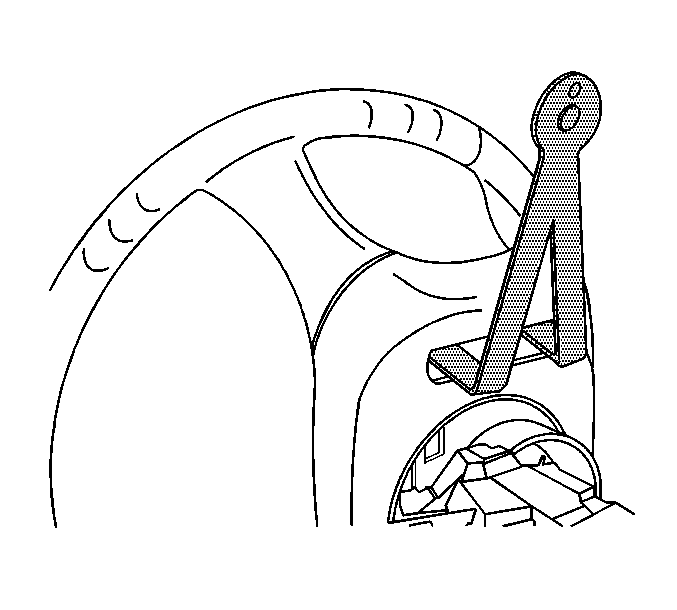
J 44298 Driver Air Bag Removal Tool
Removal Procedure
- Disable the SIR system. Refer to Disabling the SIR System .
- On the back side of the steering wheel are 4 openings/holes for removing the driver inflator module.
- Place the steering wheel so that 2 of the opening/holes are on top.
- Adjust and install J 44298 into 2 of the holes.
- Push the handle back towards the instrument panel (I/P), releasing the 2 spring loaded fasteners at the same time.
- Turn the steering wheel and open J 44298 . Use one of the tool fingers to remove cruise control lever cover in order to gain access.
- Place J 44298 and insert into place around cruise control lever and repeat for the other two opening/holes.
- Pull the driver inflator module gently away from the steering wheel.
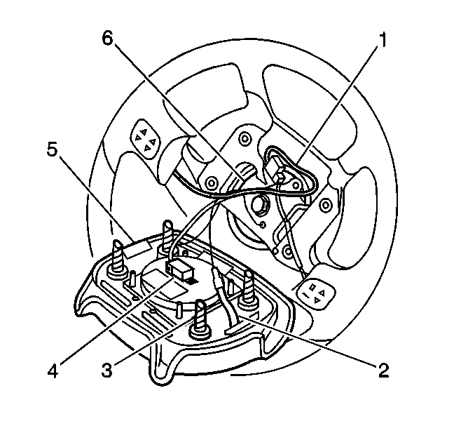
- Remove the connector position assurance (CPA) (4) and the electrical connector from the driver inflator module.
- Remove the horn grounded lead (2) from the threaded hole in the steering wheel.
- Rotate the horn contact lead counterclockwise ¼ turn.
- Remove the horn contact lead (2) from the steering column cam tower.
- Remove the steering wheel module (5).
- Fully deploy the module before disposal. If the module was replaced under warranty, fully deploy and dispose of the module after the required retention period. Refer to Inflator Module Handling and Scrapping .

Caution: When you are carrying an undeployed inflator module:
• Do not carry the inflator module by the wires or connector on
the inflator module • Make sure the bag opening points away from you
Important: Seat the air bag removal tool all the way in to perform properly.

Important: Note the driver inflator wire routing positions, the redundant control routing positions, and the horn wire routing positions for the correct re-assembly.
Caution: Following the deployment of a side impact air bag, inspect the following
parts for damage. Replace these parts if necessary:
• The seat cushion frame • The seat recliner, if equipped • The seat adjuster • The seat back frame
Installation Procedure
- Connect the horn ground lead (2) into the lower left threaded hole in the steering wheel.
- Connect the horn contact lead into the steering column cam tower.
- Rotate the horn contact turn ¼ turn clockwise to lock.
- Connect the inflator module electrical connector and the CPA (4).
- Align the inflator module fasteners to the steering column fastener holes.
- Push the inflator module firmly into the steering column in order to engage the fasteners.
- Enable the SIR system. Refer to Enabling the SIR System .

Important: Route the driver inflator wires, the redundant control wires, and the horn wires correctly.
