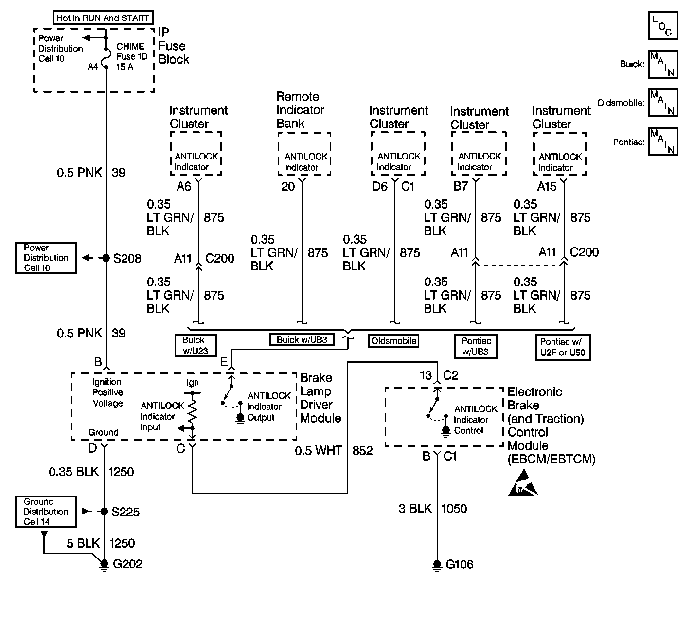
Circuit Description
The ABS Indicator driver circuit runs from the Instrument Panel Cluster (IPC) through the Brake Lamp Driver Module to the EBCM/EBTCM. The IPC supplies voltage to the ABS indicator. The EBCM/EBTCM controls the ABS indicator through the Brake Lamp Driver Module. The Brake Lamp Driver Module acts as an inventor. When the EBCM/EBTCM supplies a ground for the Brake Lamp Driver Module the ABS indicator remains Off. When the EBCM/EBTCM removes the ground for the Brake Lamp Driver Module the ABS indicator turns On by using the ground at the Brake Lamp Driver Module terminal D.
Diagnostic Aids
| • | Perform a thorough inspection of the wiring and connectors. Failure to carefully and fully inspect wiring and connectors may result in misdiagnosis, causing part replacement with reappearance of the malfunction. |
| • | In order for the ABS indicator to come On, there must be battery voltage at terminal B of the Brake Lamp Driver Module and a good ground at terminal D of the Brake Lamp Driver Module. |
| • | If the ABS indicator does not come On and there are no DTCs, then the cause may be one of the following: |
| • | A malfunctioning Brake Lamp Driver Module |
| • | CKT 875 is open |
| • | No power or ground for the Brake Lamp Driver Module |
| • | A malfunctioning IPC |
| • | A damaged ABS indicator bulb |
| • | The EBCM/EBTM sets a DTC when CKT 852 is open, shorted to ground, or shorted to voltage |
| • | More than one indicator bulb will be inoperative if the battery feed to the IPC indicators is open |
Test Description
The number(s) below refer to the step number(s) on the diagnostic table.
-
This step checks if the EBCM/EBTCM is not capable of removing the ground for CKT 852
-
This step checks for a short to ground in CKT 39.
-
This step checks for voltage at brake lamp driver module.
-
This step checks for voltage from IPC.
-
This step checks if brake lamp driver module has a good ground.
Step | Action | Value(s) | Yes | No |
|---|---|---|---|---|
1 | Was the Diagnostic System Check performed? | -- | Go to Diagnostic System Check | |
Does the ABS indicator turn on? | -- | |||
3 |
Is the fuse OK? | -- | ||
4 |
Is the voltage within the specified range? | Battery Voltage | Go to Wiring Repairs in Wiring Systems | |
Is the resistance equal to the specified value? | OL (infinite) | |||
Is the voltage within the specified range? | Battery Voltage | |||
Using J 39200 DMM, measure the voltage from terminal E of the brake lamp driver module harness connector to a good ground. Is the voltage within the specified range? | Battery Voltage | |||
8 | Repair CKT 39 for a short to ground. Refer to Wiring Repairs in Wiring Systems. Is the repair complete? | -- | Go to Diagnostic System Check | -- |
9 |
Is the fuse OK? | -- | Go to Diagnostic System Check | |
Is the resistance less than the specified value? | 2 ohms | |||
11 |
Is the resistance less than the specified value? | 2 ohms | ||
12 | Replace the brake lamp driver module. Refer to Lamp Driver Module Replacement . Is the replacement complete? | -- | Go to Diagnostic System Check | -- |
13 | Repair CKT 1250 for an open. Refer to Wiring Repairs in Wiring Systems. Is the repair complete? | -- | Go to Diagnostic System Check | -- |
14 | Suspect the IPC. Refer to Diagnostic System Check - Instrument Cluster in Instrument Panel, Gauges and Console. Is the diagnosis complete? | -- | Go to Diagnostic System Check | -- |
15 | Repair an open or high resistance in CKT 875. Refer to Wiring Repairs in Wiring Systems. Is the repair complete? | -- | Go to Diagnostic System Check | -- |
16 | Replace the EBCM/EBTCM. Refer to Electronic Brake Control Module Replacement . Is the replacement complete? | -- | Go to Diagnostic System Check | -- |
17 | Repair an open or high resistance in CKT 39. Refer to Wiring Repairs in Wiring Systems. Is the repair complete? | -- | Go to Diagnostic System Check | -- |
