Steering Shaft, Lower Bearing, and Jacket - Disassemble - Off Vehicle for Pontiac Bonneville 2000
Steering Shaft, Lower Bearing, and Jacket - Disassemble - Off Vehicle Column Shift
Tools Required
J 21854-01 Pivot
Pin Remover
- Remove the signal switch housing. Refer to
Turn Signal Switch Housing - Disassemble - Off Vehicle
.
- Remove the turn signal and multifunction switch assembly only.
Refer to
Turn Signal and Multifunction Switch Assembly - Disassemble - Off Vehicle
.
- Remove the tilt spring only. Refer to
Tilt Spring - Disassemble - Off Vehicle
.
- Remove the linear shift assembly, shift lever and the automatic
transmission shift lock control only. Refer to
Linear Shift Assembly - Disassemble - Off Vehicle
.
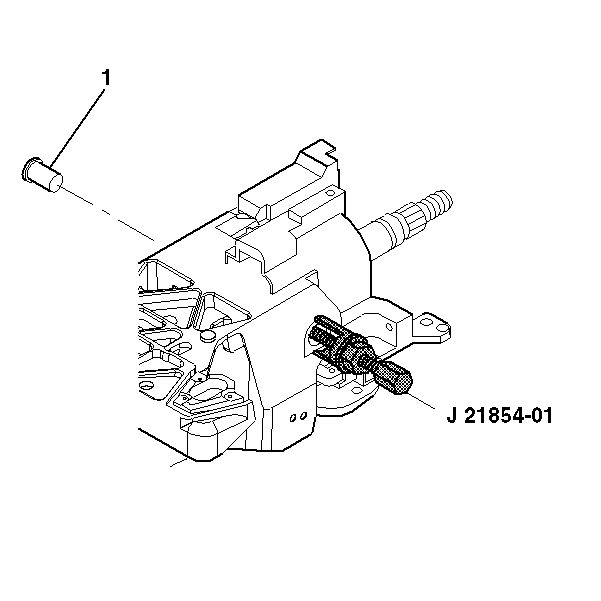
- Remove 2 pivot
pins (1) from the steering column support assembly using J 21854-01
.
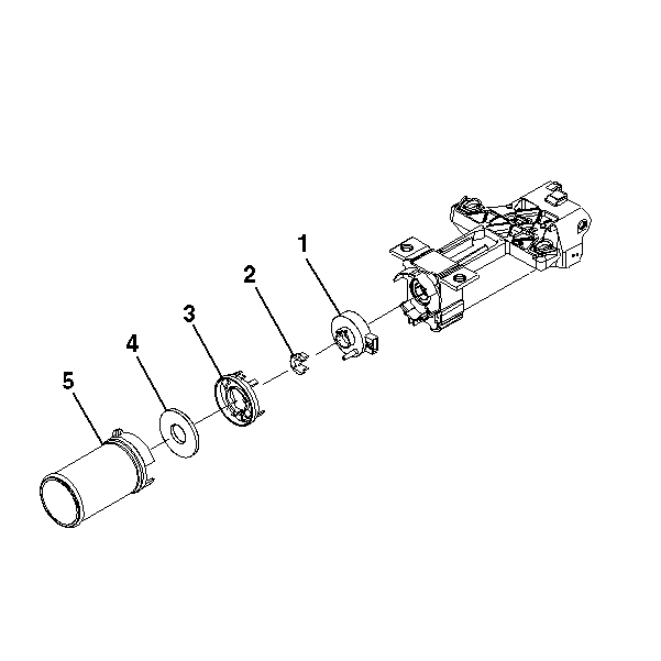
- If the sensor assembly
is present, perform the following steps:
| 6.1. | Remove the boot (5). |
| 6.2. | Remove the steering shaft seal (4). |
| 6.3. | Remove the sensor retainer (3). |
| 6.4. | Remove the sensor locator (2). |
| 6.5. | Remove the dual triangle sensor assembly (1). |
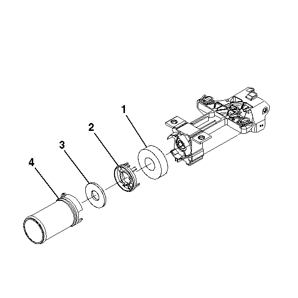
- If you do not have a sensor
assembly, perform the following steps:
| 7.1. | Remove the boot (4). |
| 7.2. | Remove the steering shaft seal (3). |
| 7.3. | Remove the sensor retainer (2). |
| 7.4. | Remove the boot seal (1). |
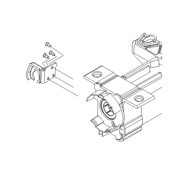
- Remove the 3 flat
head screws.
- Remove the cable support bracket.
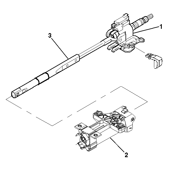
- Remove the tilt head assembly (1)
from the steering column support assembly (2) with the lower steering
shaft (3) still attached.
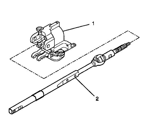
- Remove the tilt head assembly (1)
from the steering shaft assembly (2).
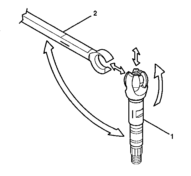
Important: Mark the race and upper shaft (1) and the lower steering shaft (2)
to ensure proper assembly. Failure to assemble properly will cause the steering
wheel to be tuned 180 degrees.
- Tilt the upper shaft assembly 90 degrees to the steering shaft
assembly and disengage.
Steering Shaft, Lower Bearing, and Jacket - Disassemble - Off Vehicle Floor Shift
Tools Required
J 21854-01 Pivot
Pin Remover
- Remove the signal switch housing. Refer to
Turn Signal Switch Housing - Disassemble - Off Vehicle
.
- Remove the turn signal and multifunction switch assembly only.
Refer to
Turn Signal and Multifunction Switch Assembly - Disassemble - Off Vehicle
.
- Remove the tilt spring only. Refer to
Tilt Spring - Disassemble - Off Vehicle
.
- Remove 2 pivot
pins (1) from the steering column support assembly using J 21854-01
.
- If the sensor assembly
is present, perform the following steps:
| 5.1. | Remove the boot (5). |
| 5.2. | Remove the steering shaft seal (4). |
| 5.3. | Remove the sensor retainer (3). |
| 5.4. | Remove the sensor locator (2). |
| 5.5. | Remove the dual triangle sensor assembly (1). |
- If you do not have a sensor
assembly, perform the following steps:
| 6.1. | Remove the boot (4). |
| 6.2. | Remove the steering shaft seal (3). |
| 6.3. | Remove the sensor retainer (2). |
| 6.4. | Remove the boot seal (1). |
- Remove the 3 flat
head screws.
- Remove the cable support bracket.
- Remove the tilt head assembly (1)
from the steering column support assembly (2) with the lower steering
shaft (3) still attached.
- Remove the tilt head assembly (1)
from the steering shaft assembly (2).
Important: Mark the race and upper shaft (1) and the lower steering shaft (2)
to ensure proper assembly. Failure to assemble properly will cause the steering
wheel to be turned 180 degrees.
- Tilt the upper shaft assembly 90 degrees to the steering shaft
assembly and disengage.

