Intake Manifold Replacement Upper
Removal Procedure
- Disconnect the intake air temperature (IAT) sensor electrical connector.
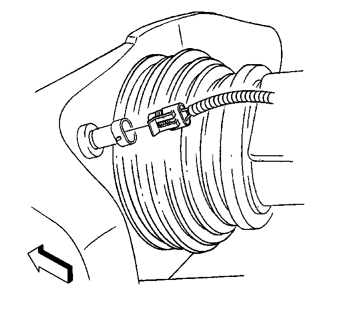
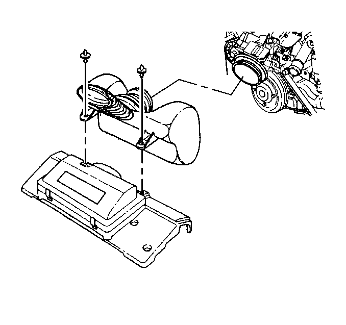
- Remove the air intake duct.
- Remove the drive belt tensioner. Refer to Drive Belt Tensioner Replacement .
- Disconnect the fuel pressure regulator vacuum and EVAP emission canister purge harness (3) from the following:
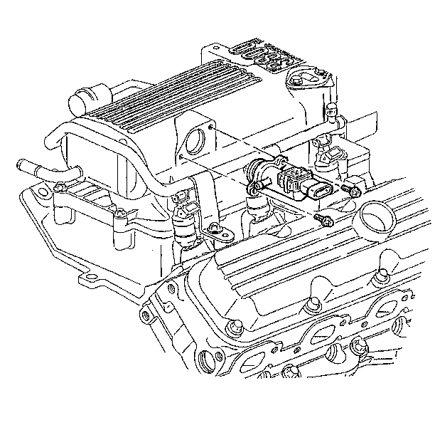
- Disconnect the manifold vacuum source electrical connector.
- Remove the manifold vacuum source screws.
- Remove the manifold vacuum source from the upper intake manifold.
- Disconnect the canister purge solenoid valve electrical connector and hose.
- Remove the evaporative emissions canister purge solenoid valve.
- Remove the idle air control (IAC) valve from the upper intake manifold. Refer to Idle Air Control Valve Replacement in Engine Controls-3.8L.
- Relieve the fuel pressure. Refer to Fuel Pressure Relief in Engine Controls-3.8L.
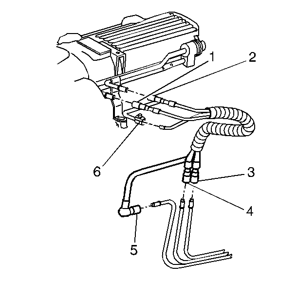
- Disconnect the fuel feed pipe (1) from the fuel rail.
- Disconnect the fuel return pipe (2) from the fuel rail.
- Disconnect the EVAP pipe (6) at the engine.
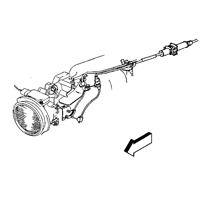
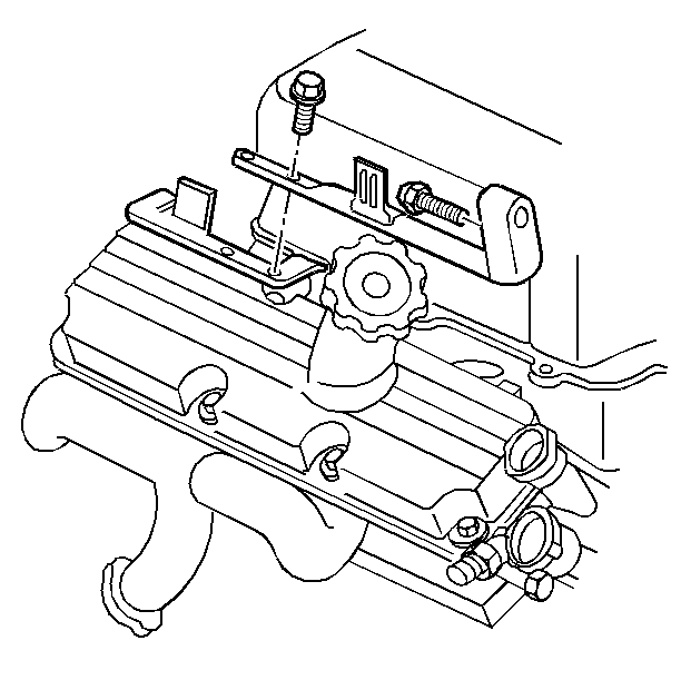
- Remove the cruise control and accelerator control cables from the throttle body and bracket.
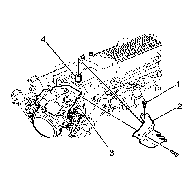
- Remove the accelerator control cable bracket bolts (1) and bracket (2).
- Remove the ignition control module. Refer to Ignition Coil and Ignition Coil Module Replacement in Engine Electrical.
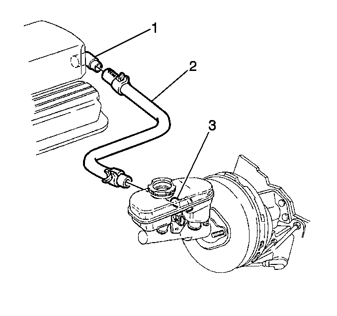
- Remove the brake booster vacuum hose (2) from the intake manifold fitting (1).
- Remove the generator brace bolts.
- Remove the generator brace from the lower intake manifold.
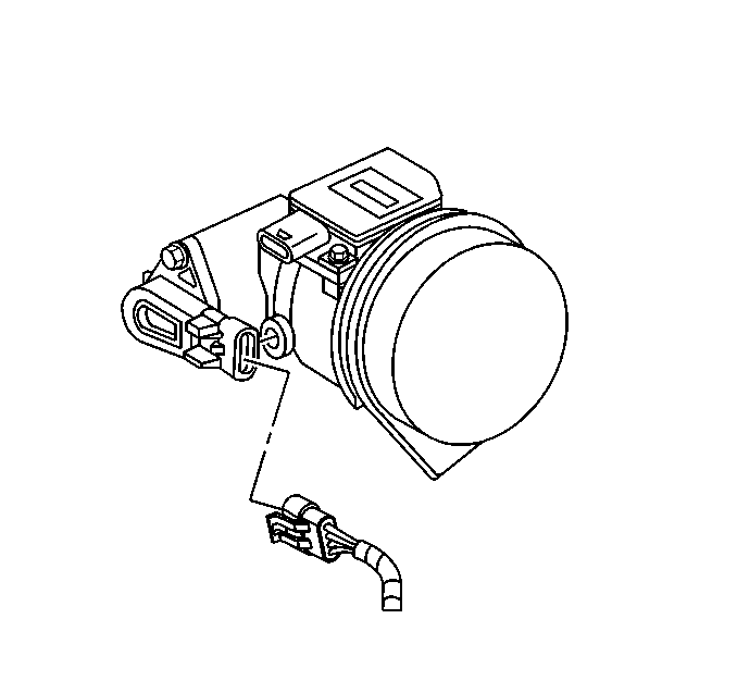
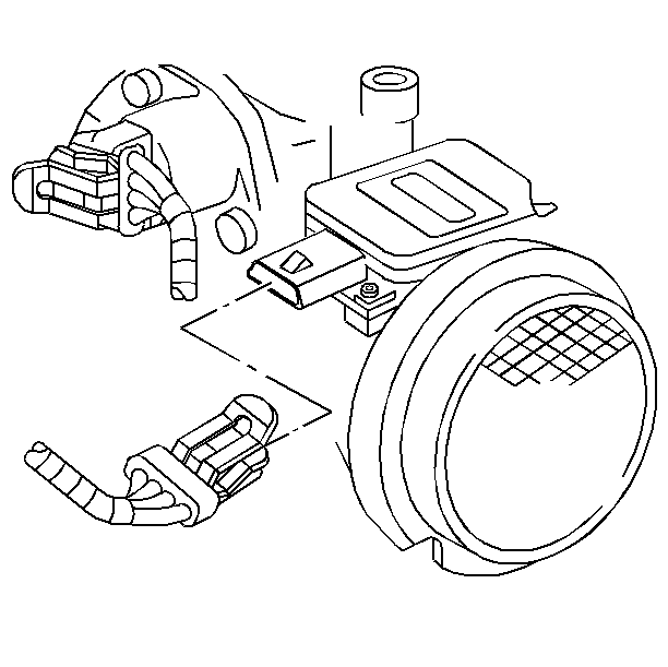
- Disconnect the idle air control (IAC) valve electrical connector.
- Disconnect the throttle position (TP) sensor electrical connector.
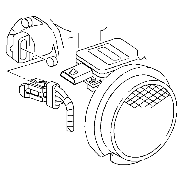
- Disconnect the mass airflow (MAF) sensor electrical connector.
- Remove the wiring harness from the rosebud clips at the fuel rail.
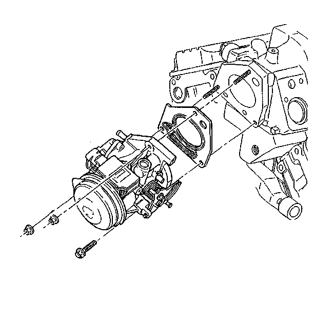
- Remove the throttle body from the upper intake manifold.
- Remove the thermostat and thermostat housing. Refer to Engine Coolant Thermostat Replacement in Engine Cooling.
- Disconnect the fuel injector electrical connectors.
- Remove the fuel rail nuts.
- Remove the fuel rail.
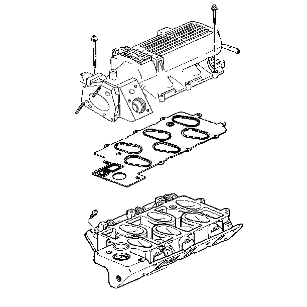
- Remove the upper intake manifold bolts.
- Remove the upper intake manifold.
- Remove the upper intake manifold gasket.
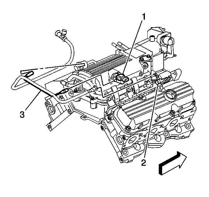
| • | Manifold vacuum source (1) |
| • | Purge solenoid valve (2) |
| • | Fuel pressure regulator valve |
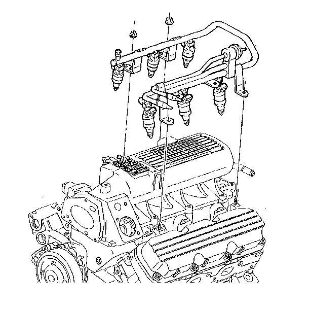
Important: Clean the dirt out of the injector bores with compressed air.
Installation Procedure
- Install the upper intake manifold gasket.
- Install the upper intake manifold.
- Install the upper intake manifold bolts.
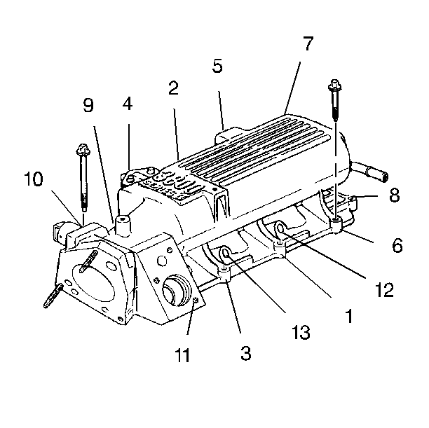
- Tighten in sequence the vertical intake manifold bolts (1-10) to 15 N·m (11 lb ft).
- Tighten the two water outlet bolts (11) to 27 N·m (20 lb ft).
- Tighten the side bolts (12, 13) to 30 N·m (22 lb ft).
- Perform the following to install the fuel rail to the upper intake manifold:
- Install the fuel rail nuts.
- Connect the fuel injector electrical connectors.
- Install the thermostat and thermostat housing. Refer to Engine Coolant Thermostat Replacement in Engine Cooling.
- Install the throttle body to the upper intake manifold studs.
- Install the throttle body bolt and nuts.
- Install the wiring harness to the rosebud clips on the fuel rail.
- Connect the mass airflow (MAF) sensor electrical connector.
- Connect the throttle position (TP) sensor electrical connector.
- Connect the idle air control (IAC) valve electrical connector.
- Install the generator brace to the upper intake manifold.
- Install the generator brace bolts.
- Install the brake booster vacuum hose (2) to the intake manifold fitting (1).
- Install the ignition control module. Refer to Ignition Coil and Ignition Coil Module Replacement in Engine Electrical.
- Install the accelerator control cable bracket (2) and bracket bolts (1).
- Install the accelerator control and cruise control cables to the throttle body and bracket.
- Connect the EVAP pipe (6) at the engine.
- Connect the fuel return pipe (2) to the fuel rail.
- Connect the fuel feed pipe (1) to the fuel rail.
- Install the idle air control (IAC) valve to the upper intake manifold. Refer to Idle Air Control Valve Replacement in Engine Controls-3.8L.
- Install the evaporative emissions canister purge solenoid valve.
- Connect the canister purge solenoid valve electrical connector and hose.
- Install the manifold vacuum source to the upper intake manifold.
- Install the manifold vacuum source screws.
- Connect the manifold vacuum source electrical connector.
- Connect the fuel pressure regulator vacuum and EVAP emission canister purge harness (3) to the following:
- Install the drive belt tensioner. Refer to Drive Belt Tensioner Replacement .
- Install the air intake duct.
- Connect the intake air temperature (IAT) sensor electrical connector.

Notice: Use the correct fastener in the correct location. Replacement fasteners must be the correct part number for that application. Fasteners requiring replacement or fasteners requiring the use of thread locking compound or sealant are identified in the service procedure. Do not use paints, lubricants, or corrosion inhibitors on fasteners or fastener joint surfaces unless specified. These coatings affect fastener torque and joint clamping force and may damage the fastener. Use the correct tightening sequence and specifications when installing fasteners in order to avoid damage to parts and systems.
Tighten

| 4.1. | Using clean engine oil, lubricate the fuel injector O-rings. |
| 4.2. | Install the injectors into the bores of the manifold. |
| 4.3. | Carefully press the fuel rail down with the palms of both hands until the injectors are fully seated. |
Tighten
Tighten the fuel rail nuts to 8.5 N·m (75 lb in).

Tighten
| • | Tighten the throttle body bolt to 10 N·m (89 lb in). |
| • | Tighten the throttle body nuts to 10 N·m (89 lb in). |


Tighten
Tighten the generator brace bolts to 25 N·m (18 lb ft).


Tighten
Tighten the accelerator control cable bracket bolts (1) to 16 N·m
(12 lb ft).


Tighten
Tighten the manifold vacuum source screws to 10 N·m (89 lb in).

| • | Manifold vacuum source (1) |
| • | Purge solenoid valve (2) |
| • | Fuel pressure regulator valve |


Intake Manifold Replacement Lower
Removal Procedure
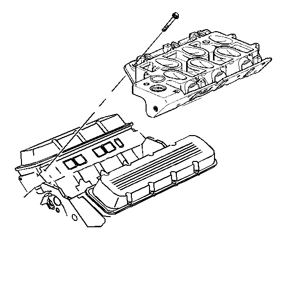
Important: Remove the upper intake manifold in order to uncover hidden bolts on the front and left rear corners of the lower intake manifold.
- Remove the upper intake manifold. Refer to Intake Manifold Replacement .
- Remove the engine coolant temperature sensor. Refer to Engine Coolant Temperature Sensor Replacement in Engine Control - 3.8L.
- Remove the lower intake manifold bolts.
- Remove the lower intake manifold.
- Remove the lower intake manifold gaskets and seals.
Installation Procedure
- Apply GM P/N 12345336 or equivalent to both the front and rear intake manifold seals.
- Install the intake manifold gaskets and seals.
- Install the lower intake manifold.
- Install the lower intake manifold bolts.
- Apply GM P/N 12345493 or equivalent thread lock compound to the bolt threads before installing.
- Torque the lower intake bolts to specifications.
- Install the engine coolant temperature sensor. Refer to Engine Coolant Temperature Sensor Replacement in Engine Control - 3.8L.
- Install the upper intake manifold. Refer to Intake Manifold Replacement .

Important: The two lower intake manifold bolts are located under the upper intake manifold. They must be installed before the upper intake manifold.
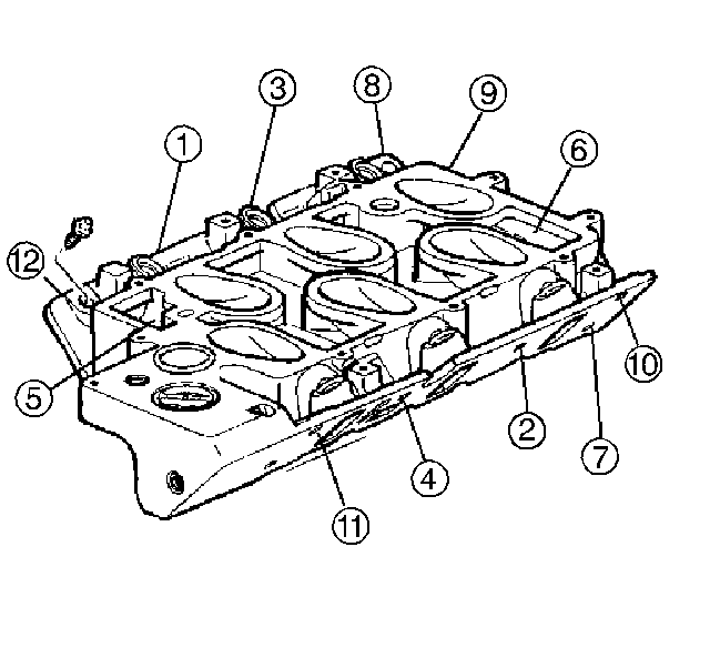
Tighten
Tighten the lower manifold bolts in sequence as shown to
15 N·m (11 lb ft).
