Propeller Shaft Diagnosis Runout Measurement
Tools Required
J 8001 Dial Indicator
Set
Important: The driveline components on this vehicle have been factory balanced.
System balancing provides a smoother running driveline operation.
Be sure to observe and accurately reference mark the positions of all
of the driveline components relative to the propeller shaft and to the rear
axle before disassembly.
The following components must be reference marked before disassembly:
| • | The drive pinion gear yoke |
| • | The published specifications |
| • | Any measurements made prior to disassembly |
Important: A bent propeller shaft may cause noise or vibrations at high speeds.
Rough handling or a collision may cause damage to the propeller shaft.
Inspect for propeller shaft straightness
- Place the transmission range selector lever in the NEUTRAL position.
- Raise the vehicle on a twin point hoist. Suitably support the
vehicle.
Ensure that the following conditions are met:
| • | The vehicle is supported on the rear axle housing |
| • | The rear wheels can rotate freely |
- Use one of the following arrangements in order to prepare the J 8001
for use:
| • | Ensure that the moveable support is high enough in order to permit contact
of the indicator button with the propeller shaft. |
| • | Mount the J 8001
onto
a magnetic base. |
| • | Attach the base to a smooth place on the underbody of the vehicle. |

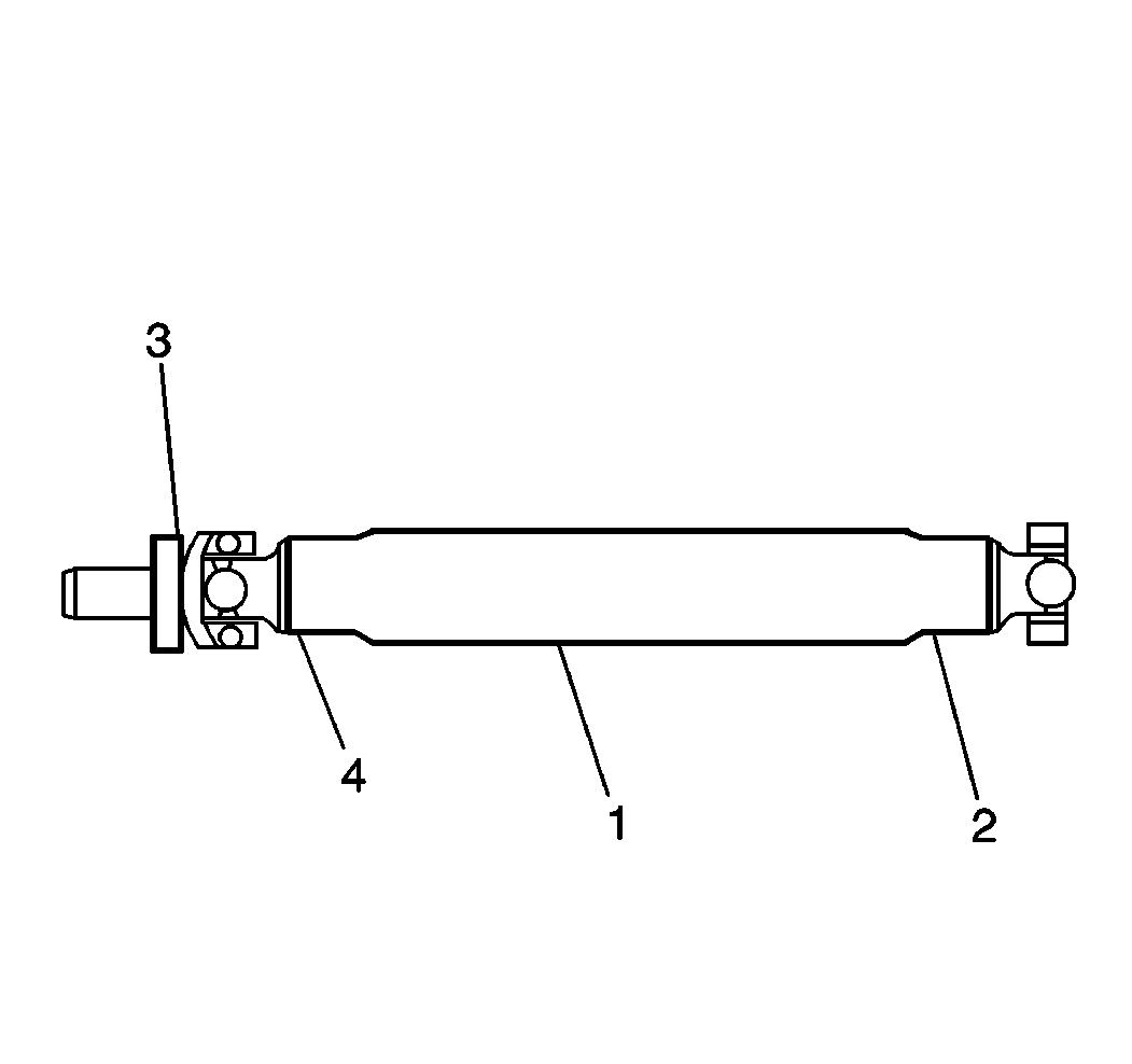
- For a one-piece propeller
shaft, take the readings at the following points:
| • | The center runout measurement point (1) |
| • | The rear runout measurement point (2) |
| • | The front runout measurement point (4) |

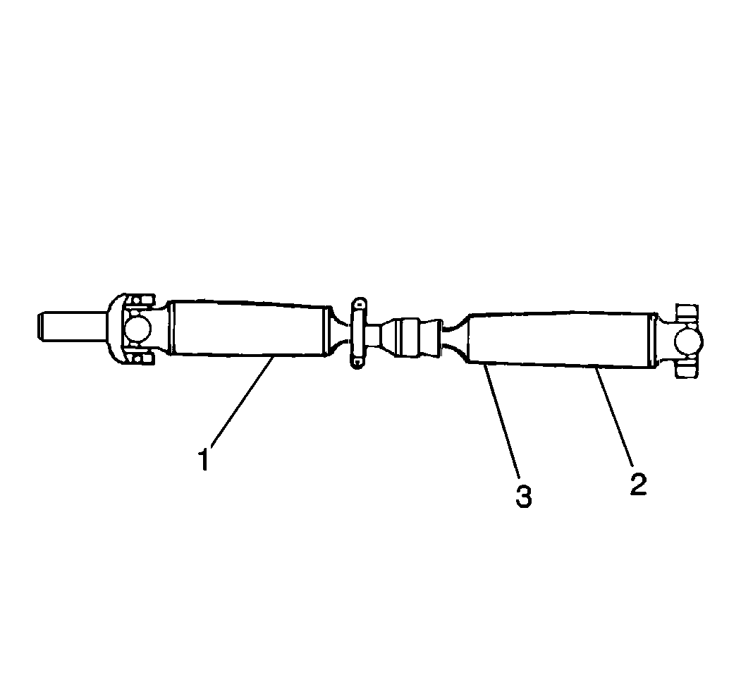
- For a two-piece propeller
shaft, take the readings at the following points:
| • | The center runout measurement point (1) |
| • | The rear runout measurement point (2) |
| • | The front runout measurement point (3) |
- Turn a rear wheel in order to rotate the propeller shaft.
Inspect for runout.
- If the runout exceeds 1.40 mm (0.055 in), complete
the following steps:
| 7.1. | Disconnect the propeller shaft at the differential drive pinion
gear yoke. |
| 7.2. | Rotate the propeller shaft 180 degrees. |
| 7.3. | Reinstall the propeller shaft. |
- Inspect for runout.
If the runout still exceeds 1.40 mm (0.055 in), measure
the differential drive pinion gear yoke runout.
Refer to
Propeller Shaft Diagnosis
.
- If the runout still exceeds 1.40 mm (0.055 in),
inspect for vibrations or noise.
If necessary, replace the propeller shaft. Refer to
One-Piece Propeller Shaft Replacement
or
Two-Piece Propeller Shaft Replacement
.
- Lower the vehicle.
Propeller Shaft Diagnosis Drive Gear Pinion Yoke Runout
Tools Required
- Raise the vehicle on a twin post hoist. Suitably support the vehicle.
Ensure that the following conditions are met:
| • | The vehicle is supported on the rear axle housing |
| • | The rear wheels can rotate freely |
- Remove the propeller shaft.
Refer to
One-Piece Propeller Shaft Replacement
or
Two-Piece Propeller Shaft Replacement
.

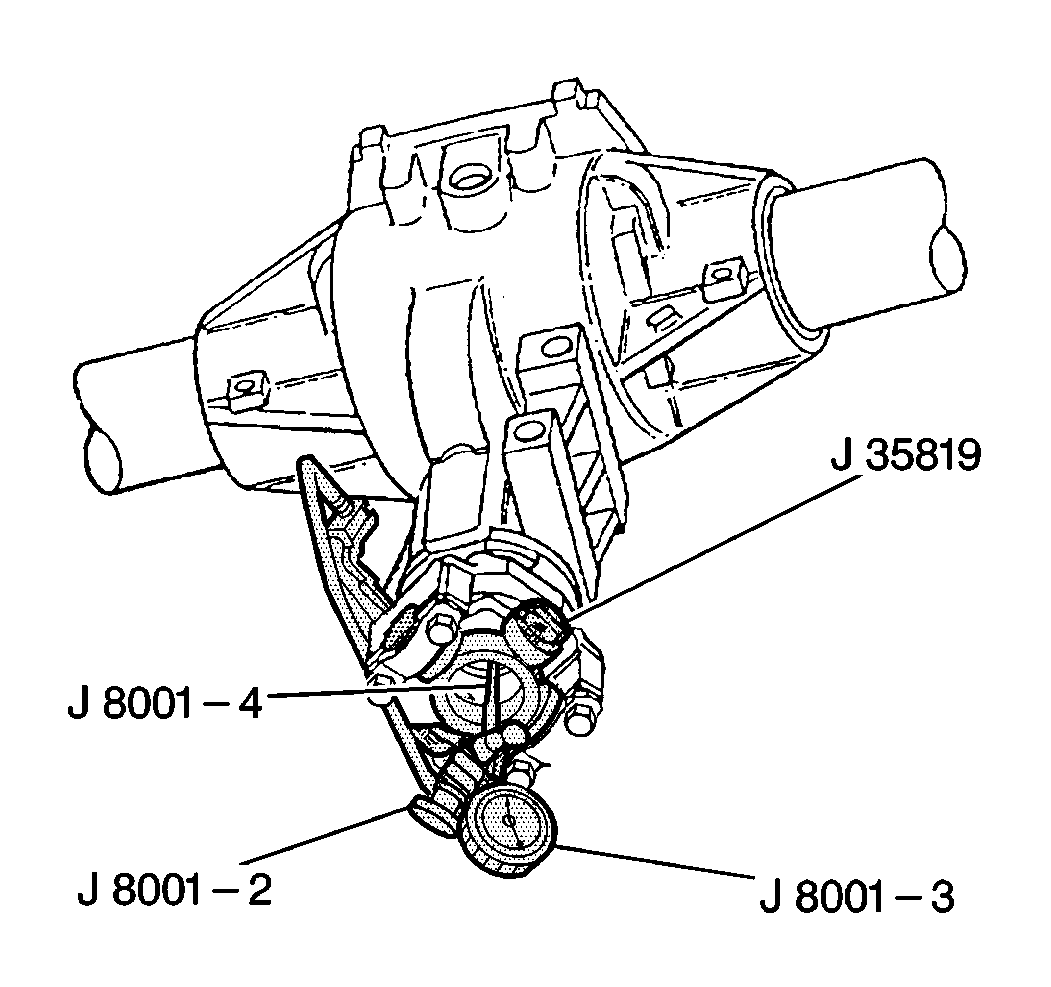
- Use the J 8001
, the J 35819
and the J 35819-100
in order to measure the pinion gear yoke runout.
Record the runout.
Mark the high point and the low point of the pinion gear yoke.
- If the pinion gear yoke runout is 0.15 mm (0.006 in)
or less, remove the pinion gear yoke balance weight, if the pinion gear yoke
balance weight is used.
No further action is required.
- No further action is required if the following circumstances exist:
| • | The pinion gear yoke runout is between 0.15-0.28 mm
(0.006-0.011 in) |
| • | The balance weight is near or at the low point of pinion gear
runout |
| • | If the balance weight is not near or at the low point of pinion gear
runout, remove the weight. |
- No further action is required if the following circumstances exist:
| • | The pinion gear yoke runout is between 0.28-0.38 mm
(0.011-0.015 in) |
| • | The balance weight is near or at the low point of pinion gear
runout |
- If the balance weight is not at or near the low point of the pinion
gear runout, complete the following steps:
| 7.2. | Rotate the pinion gear yoke until the runout is 0.25 mm
(0.010 in) or less. |
- If a runout of 0.25 mm (0.010 in) or less cannot
be attained, complete the following steps:
| | Important: Service replacement differential pinion gear yokes may be equipped with
balance weights. Do not remove these weights.
|
| 8.2. | Inspect again in order to determine if the runout is 0.25 mm
(0.010 in) or less. |
- Install the propeller shaft.
Refer to
One-Piece Propeller Shaft Replacement
or
Two-Piece Propeller Shaft Replacement
.
- Lower the vehicle.


