GM Service Manual Online
For 1990-2009 cars only
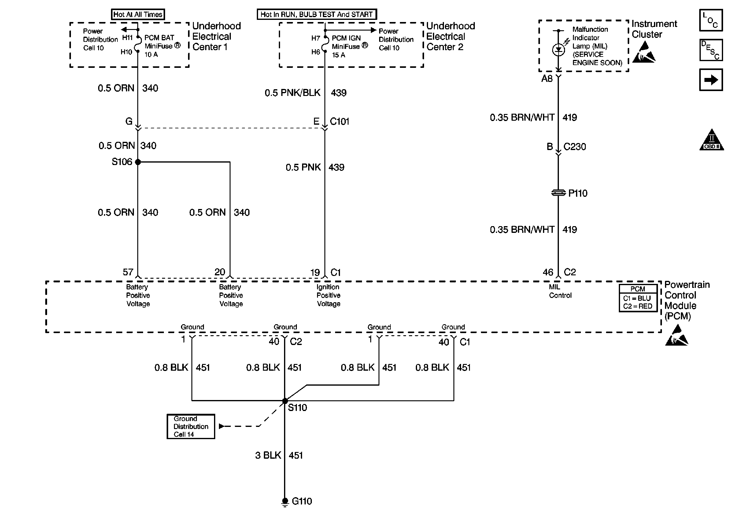
Figure 1:

Power, Ground and MIL


Object Number: 331590  Size: FS
Engine Controls Components
Powertrain Control Module Description
Data Link Connector (DLC)
OBD II Symbol Description Notice
Handling ESD Sensitive Parts Notice
Fusible Links, IP Fuse Block, and Underhood Electrical Centers
Ignition Switch and Underhood Electrical Center 2
Powertrain Control Module Connector End Views
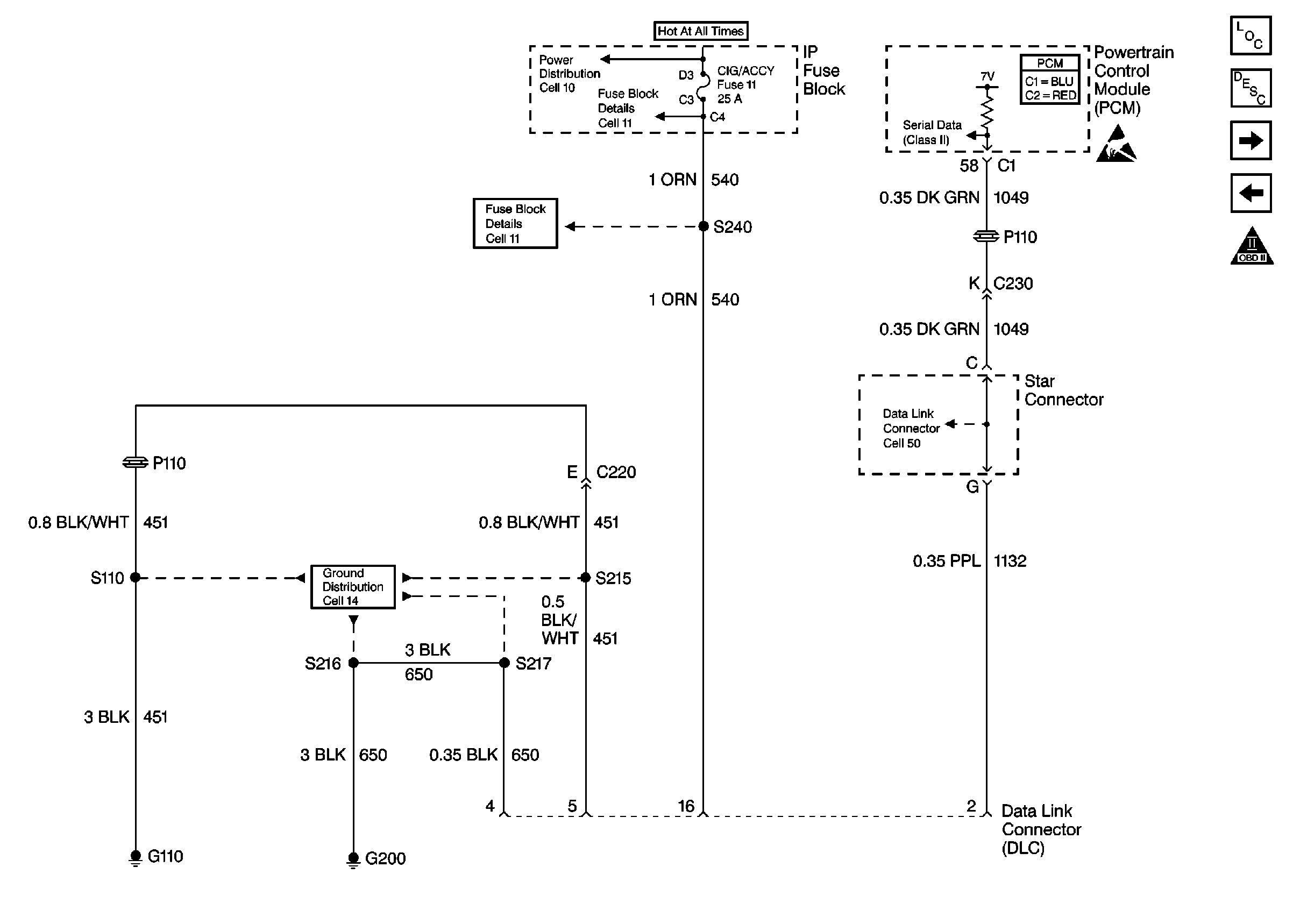
Figure 2:

Data Link Connector (DLC)


Object Number: 331606  Size: FS
Engine Controls Components
Powertrain Control Module Description
Bank 1 Ignition Coil/Modules
Power, Ground and MIL
OBD II Symbol Description Notice
Fusible Links, IP Fuse Block, and Underhood Electrical Centers
Handling ESD Sensitive Parts Notice
I/P Fuses 7, 9, 10 and 11
G200 DRL, HVAC, Rear Defog
Powertrain Control Module Connector End Views
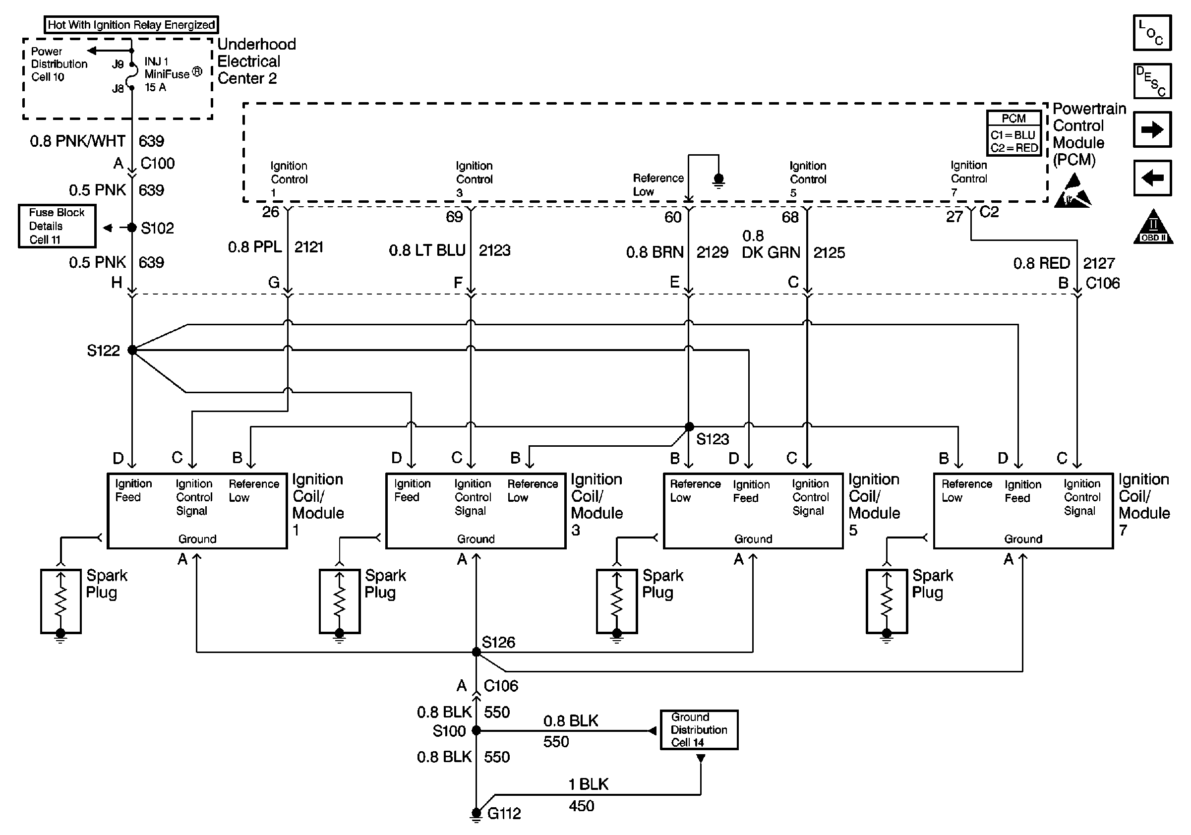
Figure 3:

Bank 1 Ignition Coil/Modules


Object Number: 331627  Size: FS
Engine Controls Components
Electronic Ignition (EI) System Description
Bank 2 Ignition Coil/Modules
Data Link Connector (DLC)
OBD II Symbol Description Notice
Ignition Switch and Underhood Electrical Center 2
G112 V8 VIN G
U/H Center 2: INJ 1 and INJ 2 Fuses
Powertrain Control Module Connector End Views
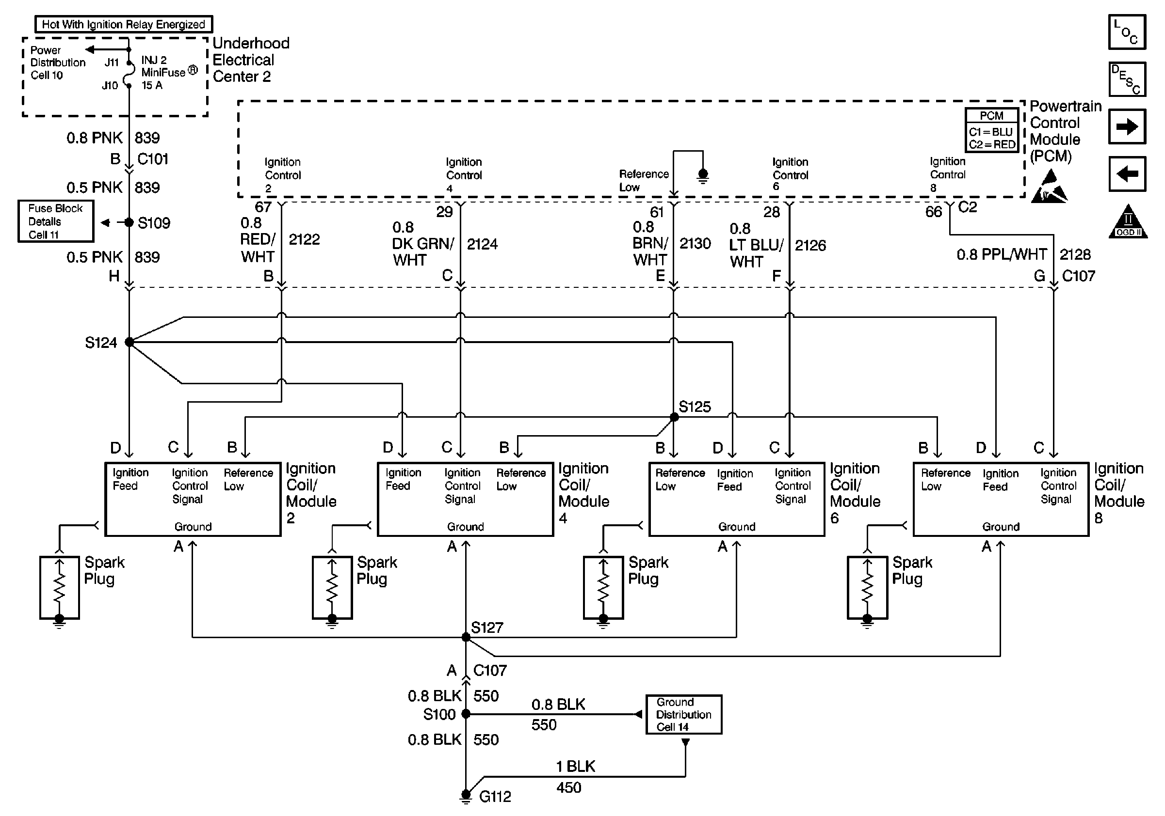
Figure 4:

Bank 2 Ignition Coil/Modules


Object Number: 331642  Size: FS
Engine Controls Components
Electronic Ignition (EI) System Description
Engine Speed Output, CKP, CMP and Knock Sensors
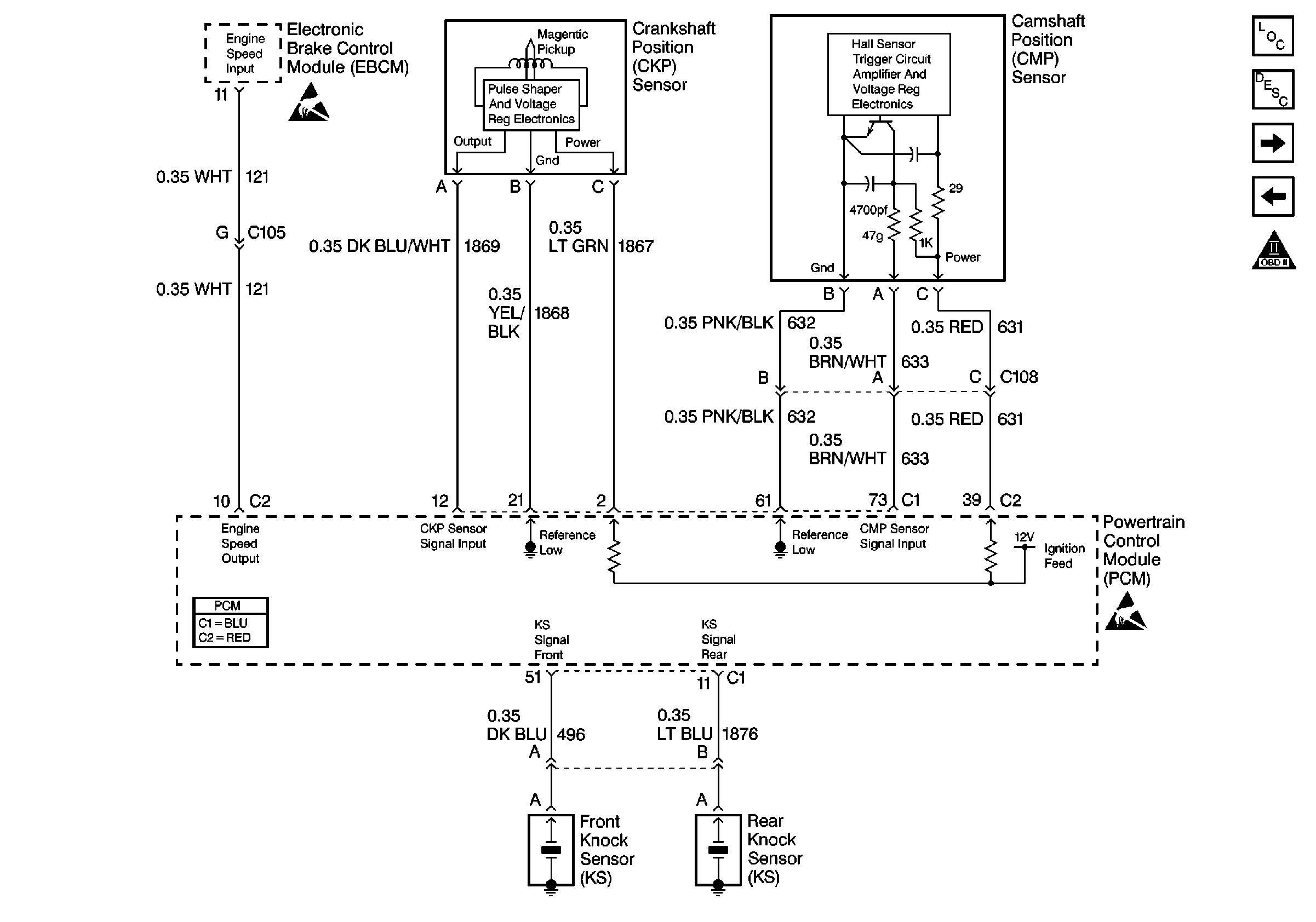
Bank 1 Ignition Coil/Modules
OBD II Symbol Description Notice
Ignition Switch and Underhood Electrical Center 2
G112 V8 VIN G
U/H Center 2: INJ 1 and INJ 2 Fuses
Powertrain Control Module Connector End Views
Figure 5:

Engine Speed Output, CKP, CMP and Knock Sensors


Object Number: 331653  Size: FS
Engine Controls Components
Electronic Ignition (EI) System Description
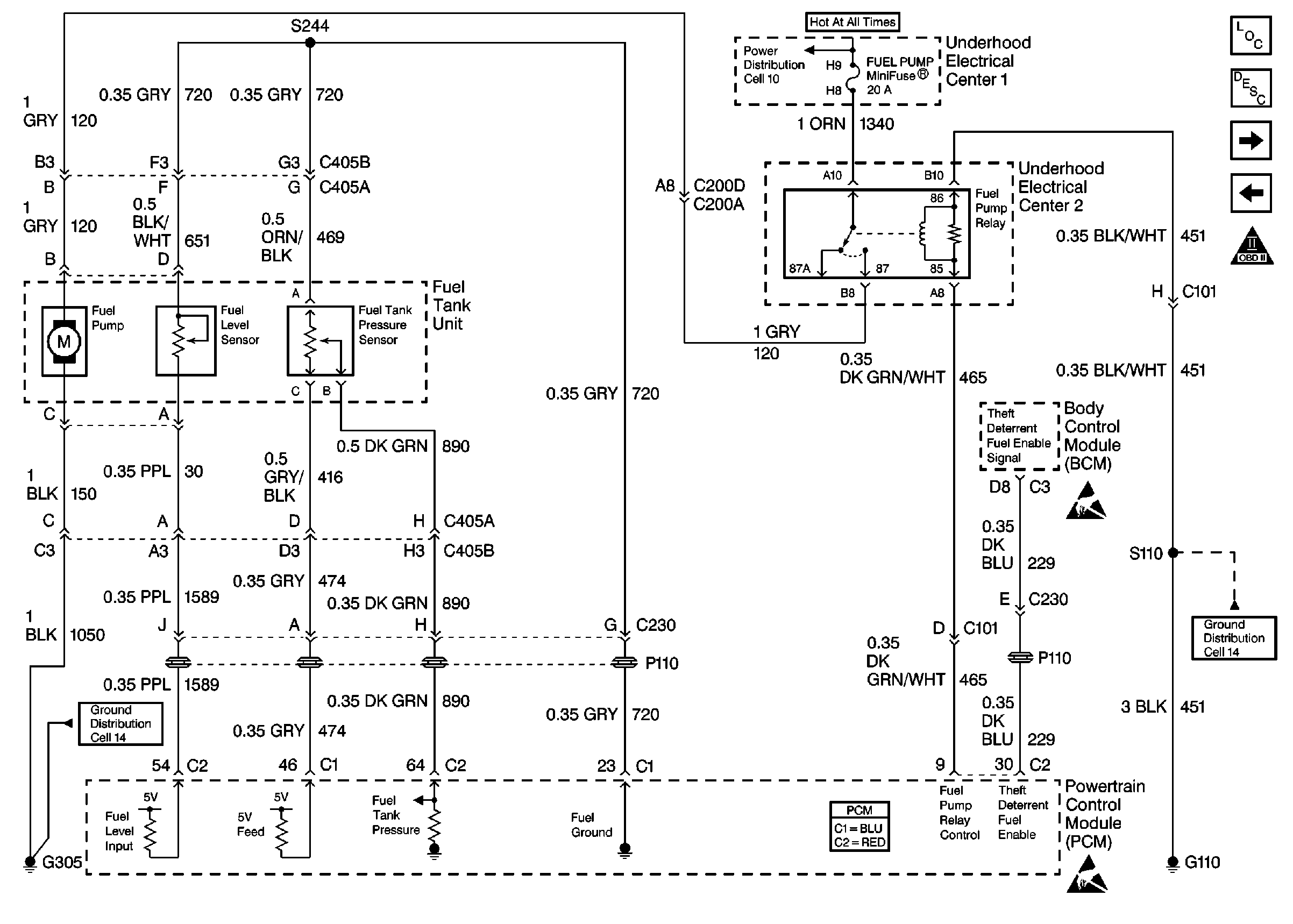
Fuel System
Bank 2 Ignition Coil/Modules
OBD II Symbol Description Notice
Handling ESD Sensitive Parts Notice
Powertrain Control Module Connector End Views
Figure 6:

Fuel System


Object Number: 331656  Size: FS
Engine Controls Components
Evaporative Emission Control System Operation Description
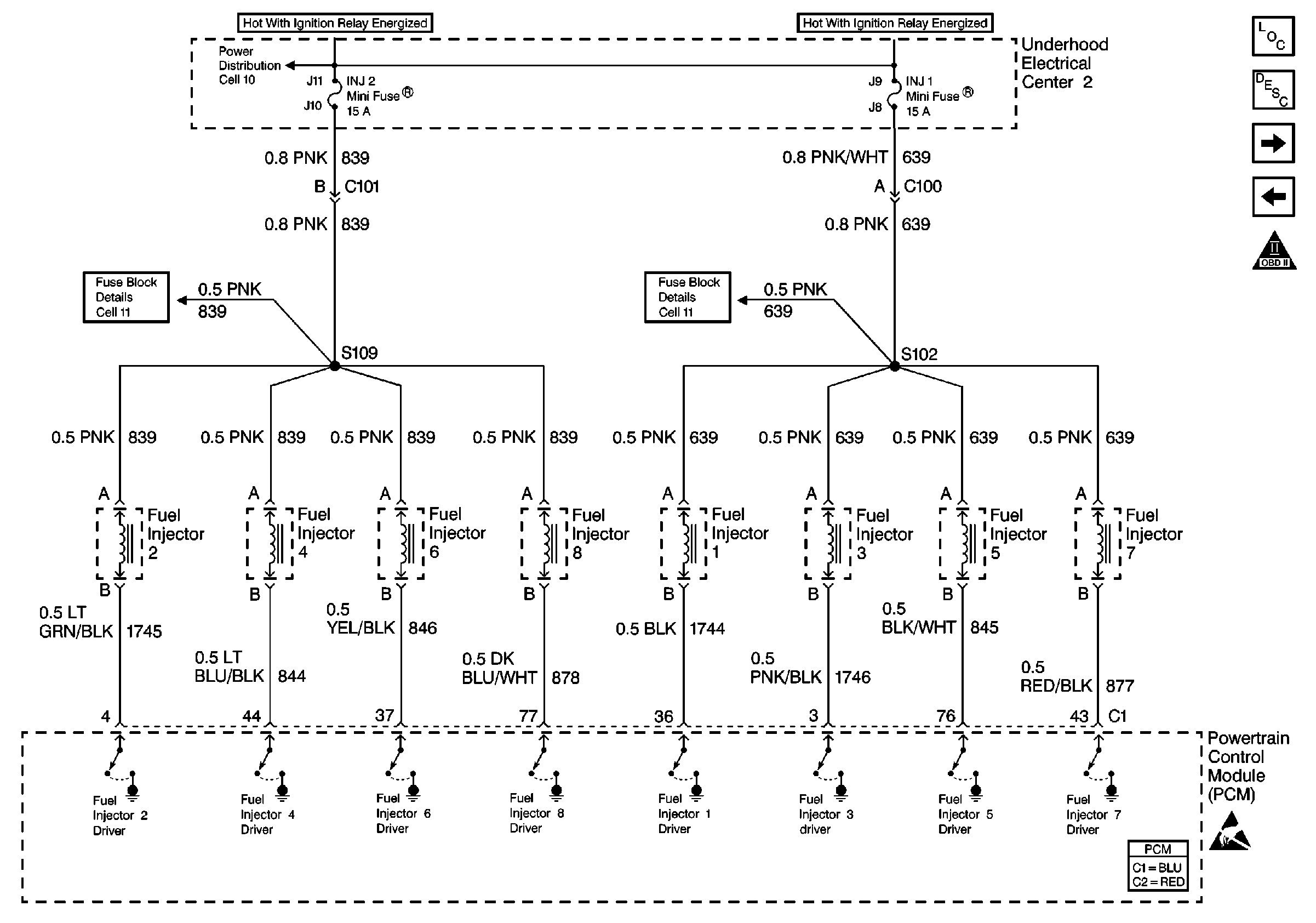
Injector Circuits
Engine Speed Output, CKP, CMP and Knock Sensors
OBD II Symbol Description Notice
Handling ESD Sensitive Parts Notice
G305, G310, G320
G110 V8 VIN G
Powertrain Control Module Connector End Views
Figure 7:

Injector Circuits


Object Number: 331660  Size: FS
Engine Controls Components
Powertrain Control Module Description
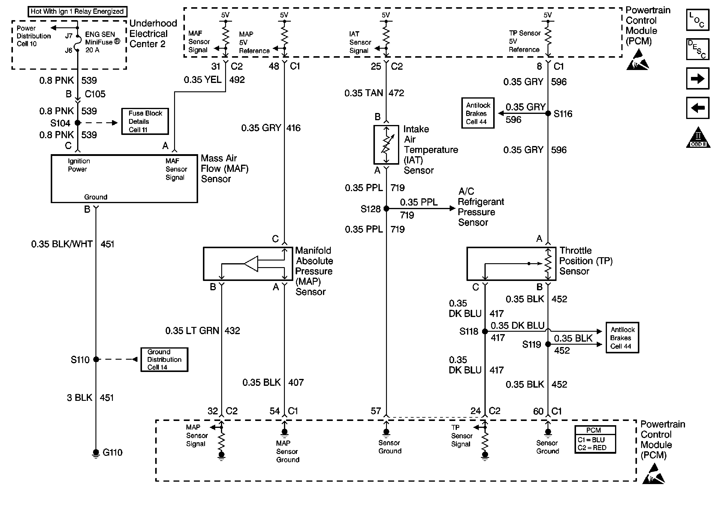
Information Sensors
Fuel System
OBD II Symbol Description Notice
Ignition Switch and Underhood Electrical Center 2
U/H Center 2: INJ 1 and INJ 2 Fuses
Powertrain Control Module Connector End Views
Figure 8:

Information Sensors


Object Number: 331663  Size: FS
Engine Controls Components
Information Sensors/Switches Description
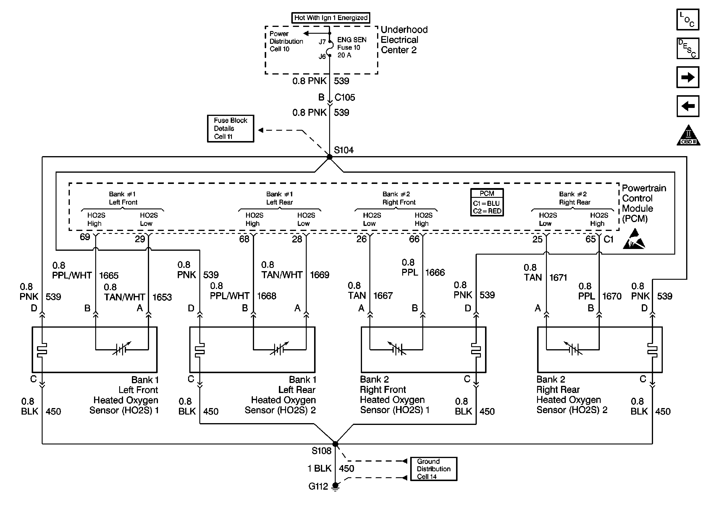
Heated Oxygen Sensors
Injector Circuits
OBD II Symbol Description Notice
Ignition Switch and Underhood Electrical Center 2
Handling ESD Sensitive Parts Notice
5.7L With Traction Control
U/H Center 2: ENG SEN Fuse
5.7L With Traction Control
G110 V8 VIN G
A/C System
Powertrain Control Module Connector End Views
Figure 9:

Heated Oxygen Sensors


Object Number: 331686  Size: FS
Engine Controls Components
Information Sensors/Switches Description
AIR and IAC
Information Sensors
OBD II Symbol Description Notice
Ignition Switch and Underhood Electrical Center 2
Handling ESD Sensitive Parts Notice
U/H Center 2: ENG SEN Fuse
G112 V8 VIN G
Powertrain Control Module Connector End Views
Figure 10:

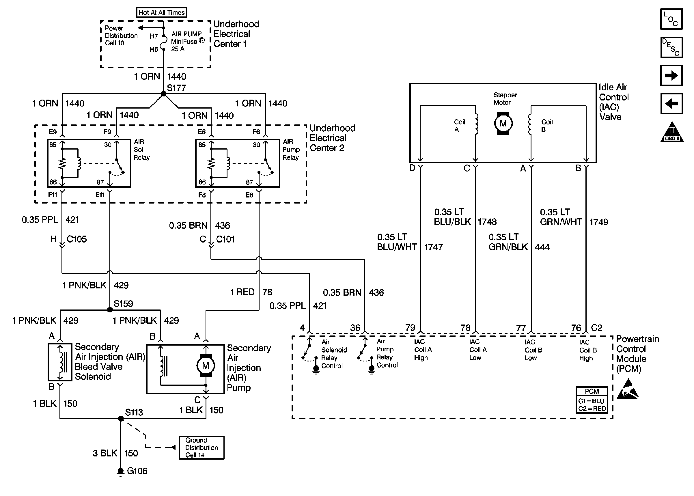
AIR and IAC


Object Number: 331688  Size: FS
Engine Controls Components
Secondary Air Injection System Description
TCS Retard Signal, VSS Output and VSS Signal
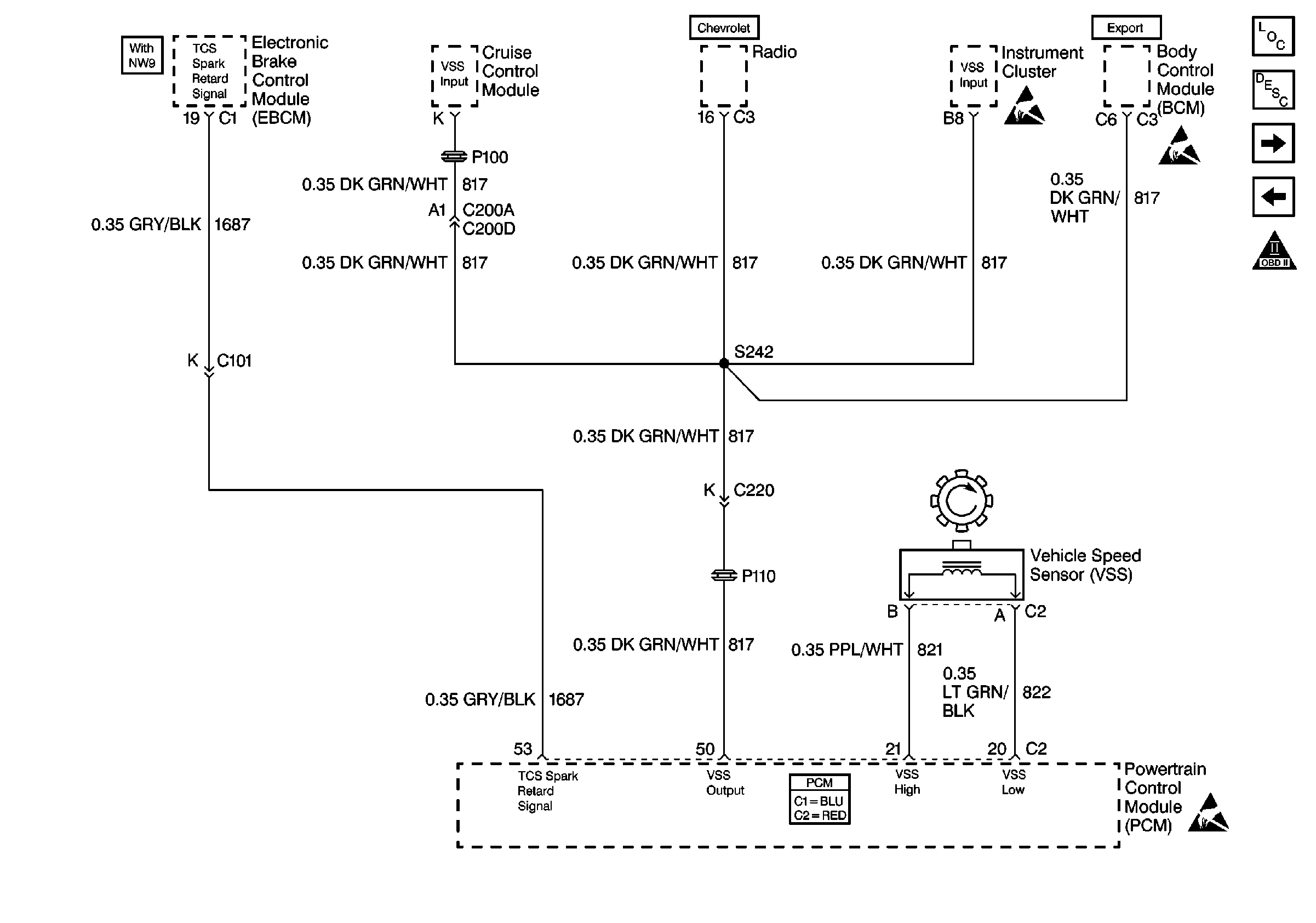
Heated Oxygen Sensors
OBD II Symbol Description Notice
Fusible Links, IP Fuse Block, and Underhood Electrical Centers
G106
Handling ESD Sensitive Parts Notice
Powertrain Control Module Connector End Views
Figure 11:

TCS Retard Signal, VSS Output and VSS Signal


Object Number: 331691  Size: FS
Engine Controls Components
Information Sensors/Switches Description
EVAP and EGR
AIR and IAC
OBD II Symbol Description Notice
Handling ESD Sensitive Parts Notice
Powertrain Control Module Connector End Views
Figure 12:

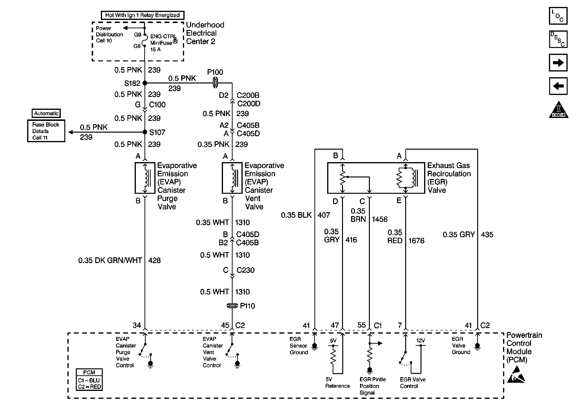
EVAP and EGR


Object Number: 331694  Size: FS
Engine Controls Components
Exhaust Gas Recirculation (EGR) System Description
Oil Level, ETC, Cruise Control and Generator
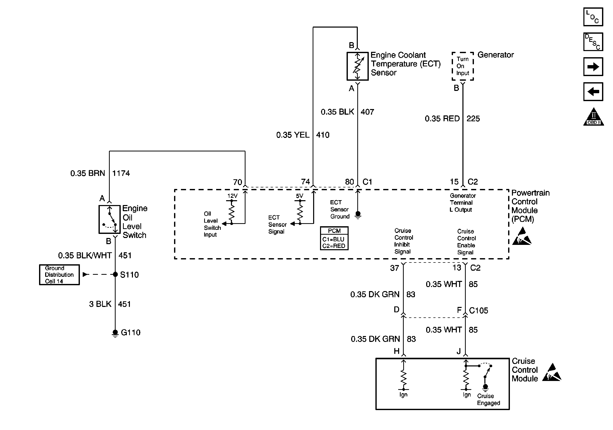
TCS Retard Signal, VSS Output and VSS Signal
OBD II Symbol Description Notice
Ignition Switch and Underhood Electrical Center 2
U/H Center 2: ENG CTRL Fuse
Handling ESD Sensitive Parts Notice
Powertrain Control Module Connector End Views
Figure 13:

Oil Level, ETC, Cruise Control and Generator


Object Number: 331696  Size: FS
Engine Controls Components
Information Sensors/Switches Description
Clutch Anticipate Switch, Reverse Inhibit and Skip Shift Solenoids
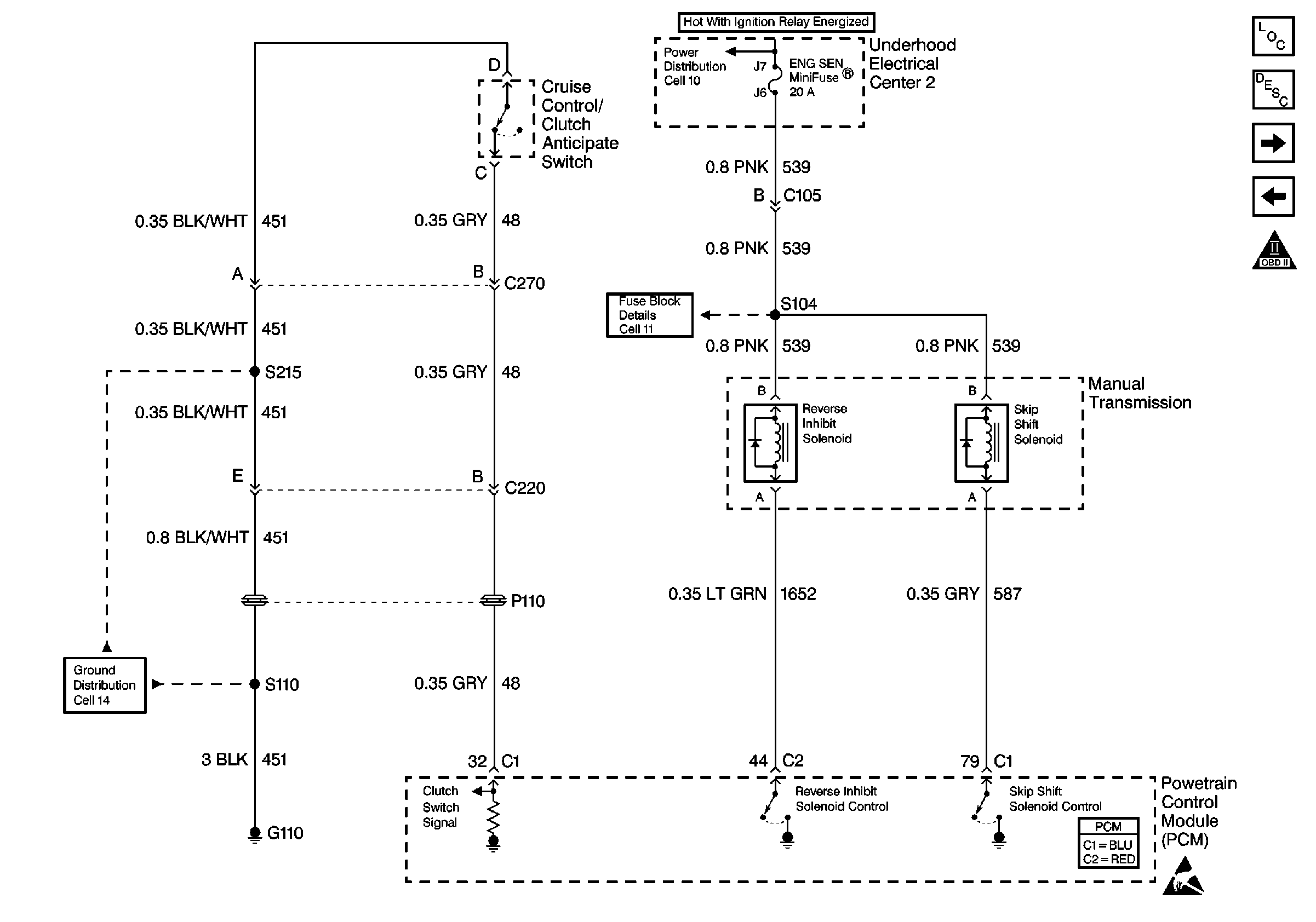
EVAP and EGR
OBD II Symbol Description Notice
G110 V8 VIN G
Handling ESD Sensitive Parts Notice
Powertrain Control Module Connector End Views
Figure 14:

Clutch Anticipate Switch, Reverse Inhibit and Skip Shift Solenoids


Object Number: 331697  Size: FS
Engine Controls Components
Powertrain Control Module Description
Automatic Transmission, Stop Lamp Switch
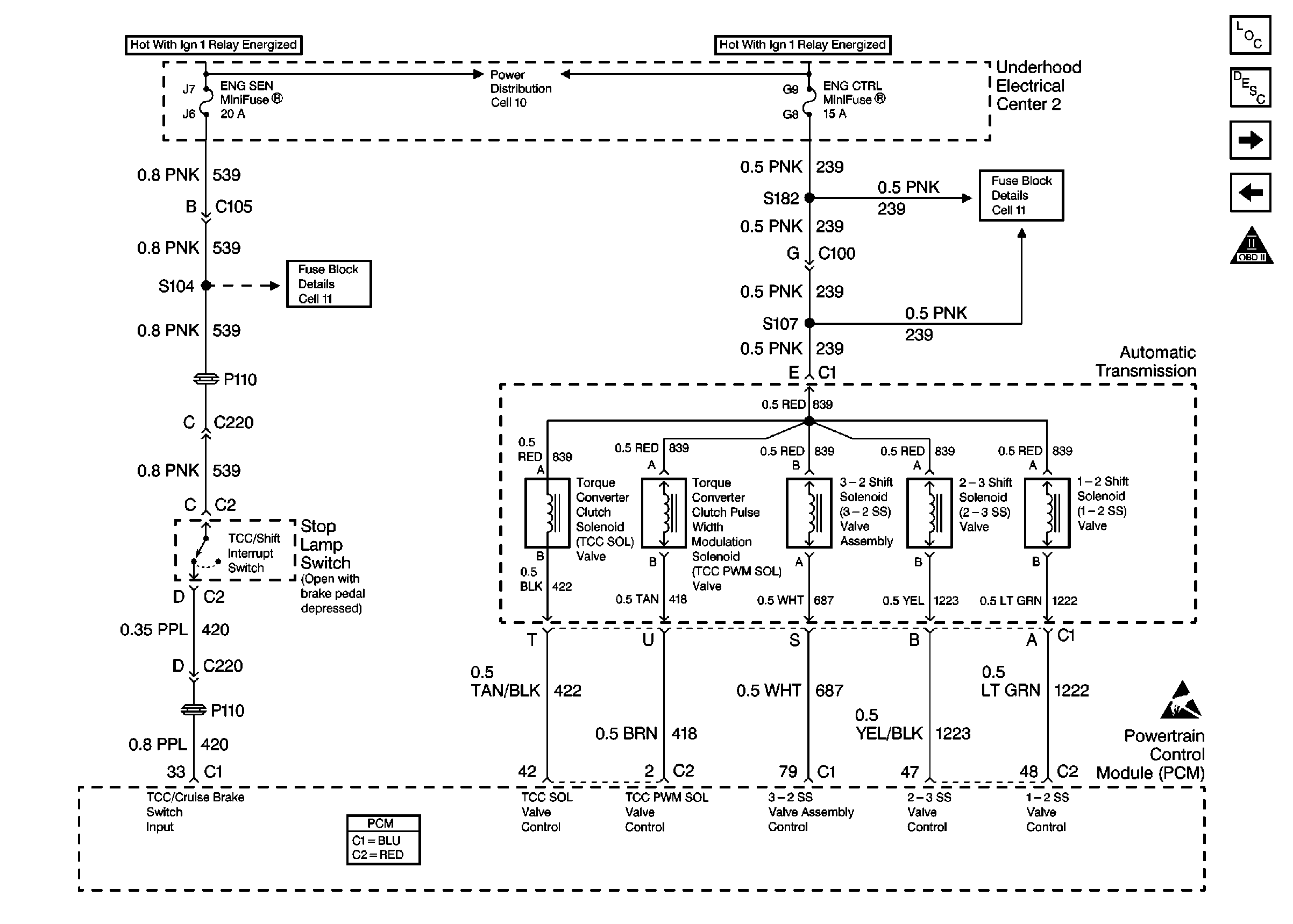
Oil Level, ETC, Cruise Control and Generator
OBD II Symbol Description Notice
Ignition Switch and Underhood Electrical Center 2
G110 V8 VIN G
Handling ESD Sensitive Parts Notice
Powertrain Control Module Connector End Views
Figure 15:

Automatic Transmission, Stop Lamp Switch


Object Number: 331699  Size: FS
Engine Controls Components
Electronic Component Description
Automatic Transmission, Park/Neutral Position Switch
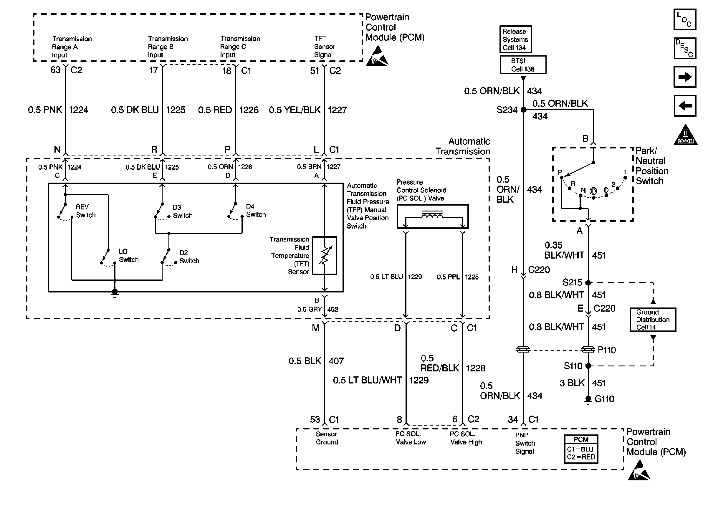
Clutch Anticipate Switch, Reverse Inhibit and Skip Shift Solenoids
OBD II Symbol Description Notice
Ignition Switch and Underhood Electrical Center 2
U/H Center 2: ENG CTRL Fuse
Handling ESD Sensitive Parts Notice
Powertrain Control Module Connector End Views
Figure 16:

Automatic Transmission, Park/Neutral Position Switch


Object Number: 331710  Size: FS
Engine Controls Components
Electronic Component Description
A/C System
Automatic Transmission, Stop Lamp Switch
OBD II Symbol Description Notice
Handling ESD Sensitive Parts Notice
DRL Module, Park Brake Switch, and Park/Neutral Position Switch
Cell 138
G110 V8 VIN G
Handling ESD Sensitive Parts Notice
Powertrain Control Module Connector End Views
Figure 17:

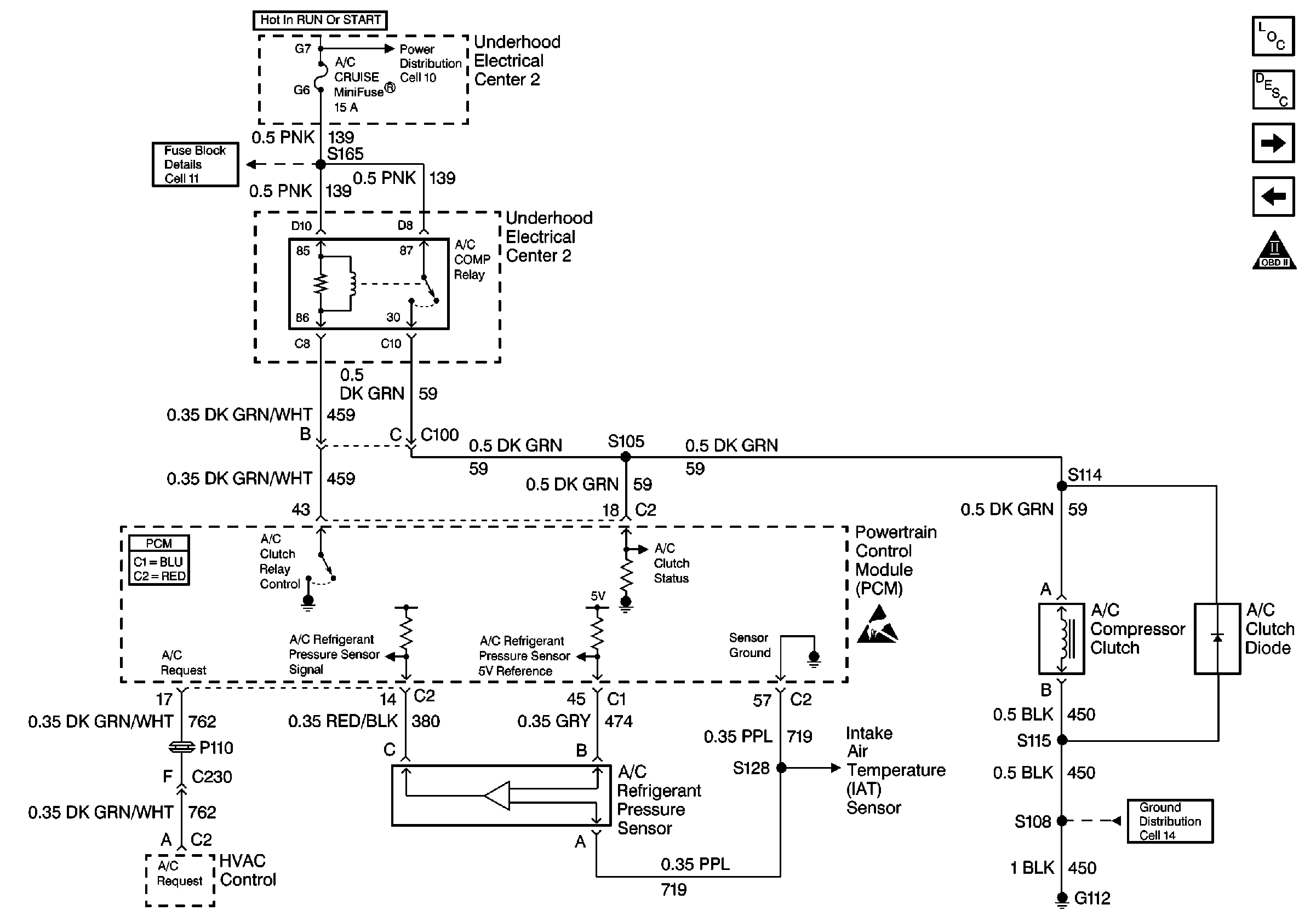
A/C System


Object Number: 331715  Size: FS
Engine Controls Components
Powertrain Control Module Controlled Air Conditioning Description
Engine Cooling Fans
Automatic Transmission, Park/Neutral Position Switch
OBD II Symbol Description Notice
Ignition Switch and Underhood Electrical Center 2
U/H Center 2: ETC and A/C Cruise Fuses
Information Sensors
G112 V8 VIN G
Powertrain Control Module Connector End Views
Figure 18:

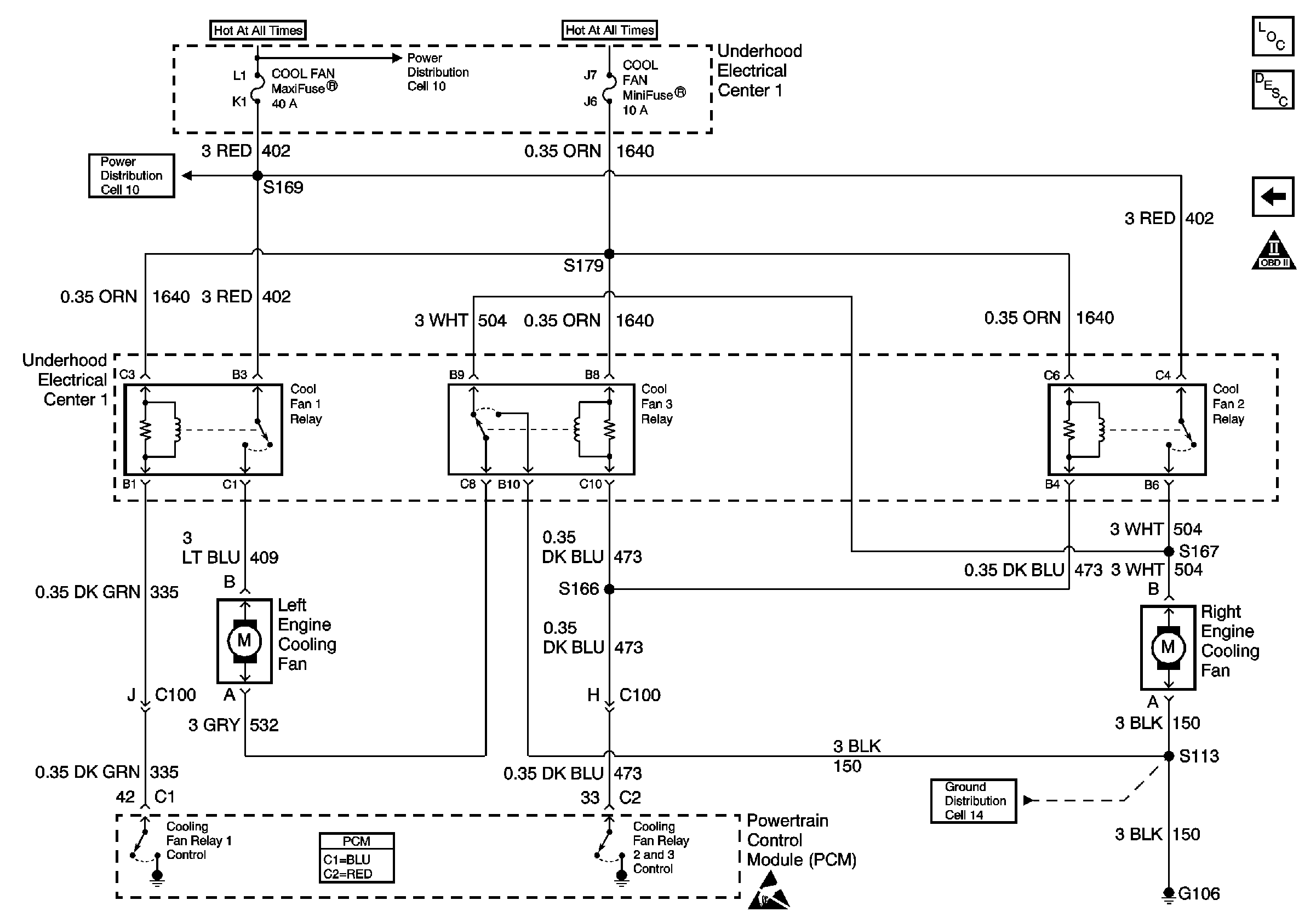
Engine Cooling Fans


Object Number: 331718  Size: FS
Engine Controls Components
Engine Cooling Fan Description - Electric
A/C System
OBD II Symbol Description Notice
Battery and Underhood Electrical Center 1
Handling ESD Sensitive Parts Notice
G106
Powertrain Control Module Connector End Views
Battery and Underhood Electrical Center 1