- Install the power brake booster onto the vehicle.

- Install the brake booster
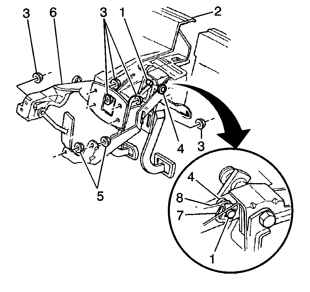
pushrod (8) to the brake pedal lever pin (1).
| 2.1. | Tilt the entire brake booster slightly in order to work the brake
booster pushrod onto the brake pedal pin. |
| 2.2. | From inside the vehicle, install the brake pedal pushrod washer
(4) and retainer (7). |
Notice: Use the correct fastener in the correct location. Replacement fasteners
must be the correct part number for that application. Fasteners requiring
replacement or fasteners requiring the use of thread locking compound or sealant
are identified in the service procedure. Do not use paints, lubricants, or
corrosion inhibitors on fasteners or fastener joint surfaces unless specified.
These coatings affect fastener torque and joint clamping force and may damage
the fastener. Use the correct tightening sequence and specifications when
installing fasteners in order to avoid damage to parts and systems.
- Install the brake
pedal nuts (3) attaching the brake booster to the brake pedal with bracket
(6).
Tighten
Tighten the brake pedal nuts to 20 N·m (15 lb ft)
in the following sequence:
- On manual transmission equipped vehicles only, install the clutch
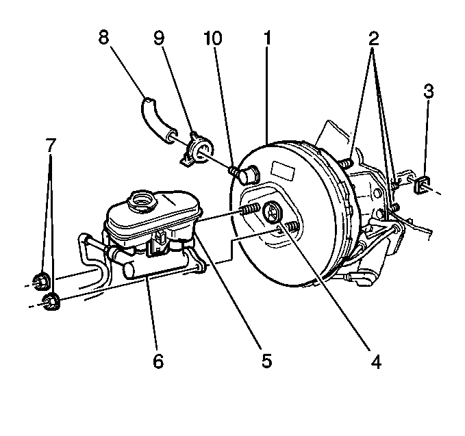
master cylinder nuts (7).
Tighten
Tighten the clutch master cylinder nuts to 27 N·m (20 lb ft).

- Install the master cylinder
(6) onto the brake booster (1).
- Install the master cylinder nuts (7) attaching the master cylinder
to the brake booster.
Tighten
Tighten the brake master cylinder nuts to 29 N·m (21 lb ft)
- Connect the vacuum hose (8) and the clamp (9) to the check valve
(10).
- Install the left side instrument insulator. Refer to
Instrument Panel Insulator Replacement
in Instrument Panel,
Gauges and Console.
- Install the left side air inlet screen. Refer to
Air Inlet Grille Panel Replacement
in Body front End.
- Instal the left and right side wiper arms. Refer to
Windshield Wiper Arm Replacement
in Wiper Washer Systems.
- Install the hood rear seal. Refer to
Hood Rear Seal Replacement
in Body Front End.
- Bleed the brakes. Refer to
Hydraulic Brake System Bleeding
.


