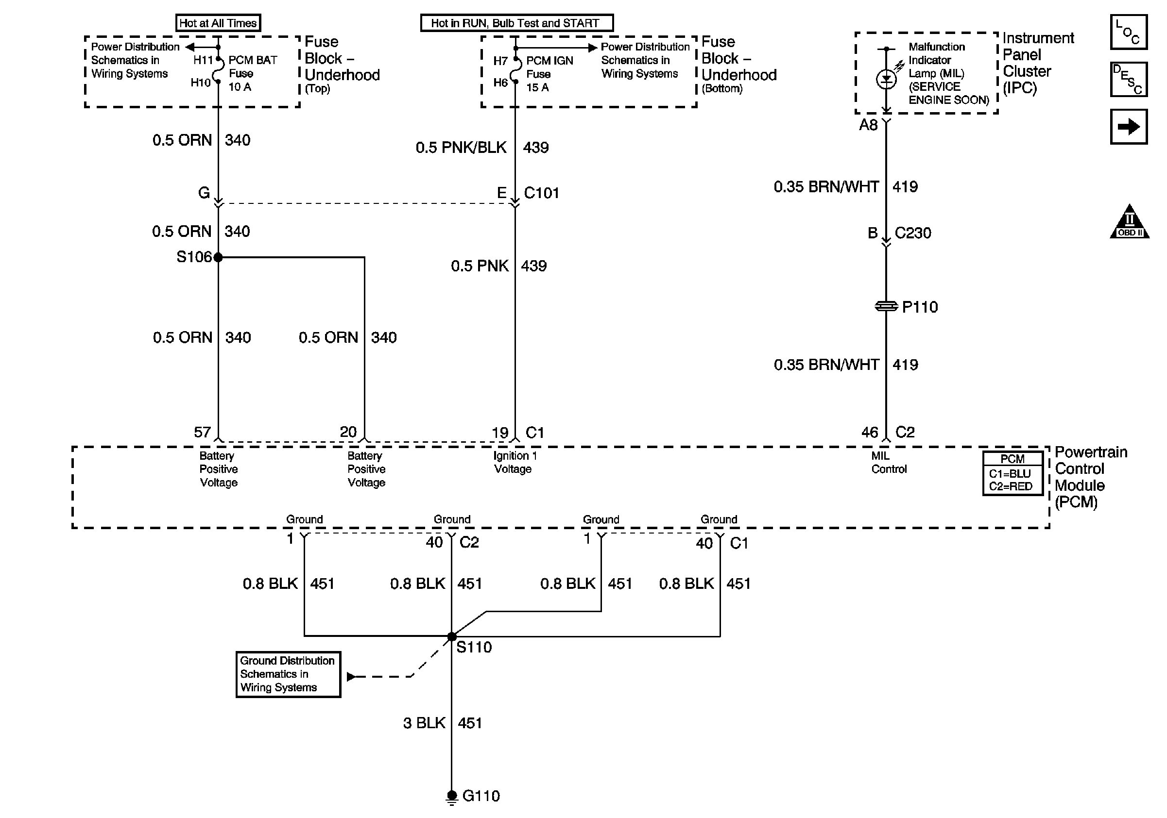
| Figure 1: |
Power and Ground
|
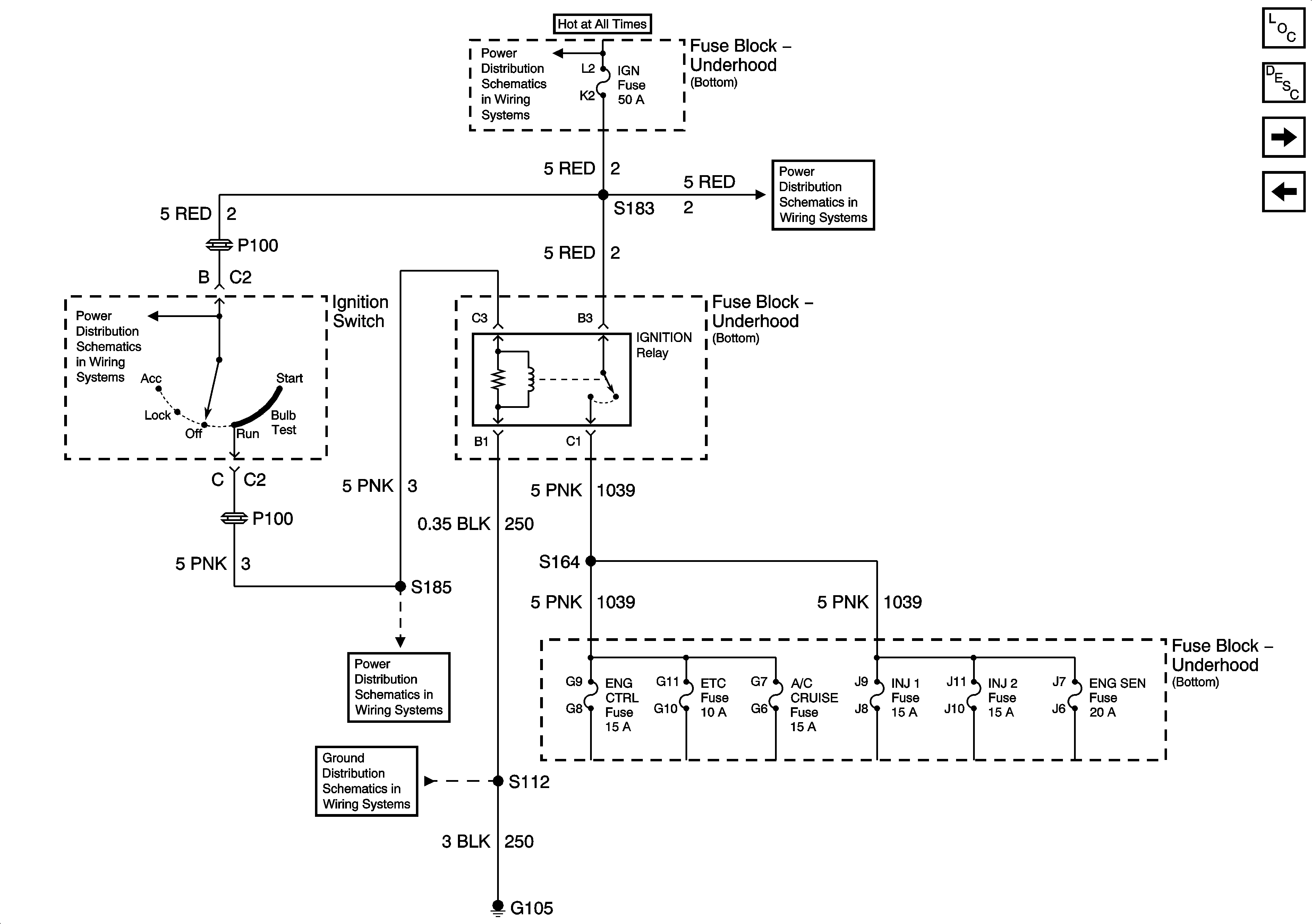
| Figure 2: |
Ignition Relay
|
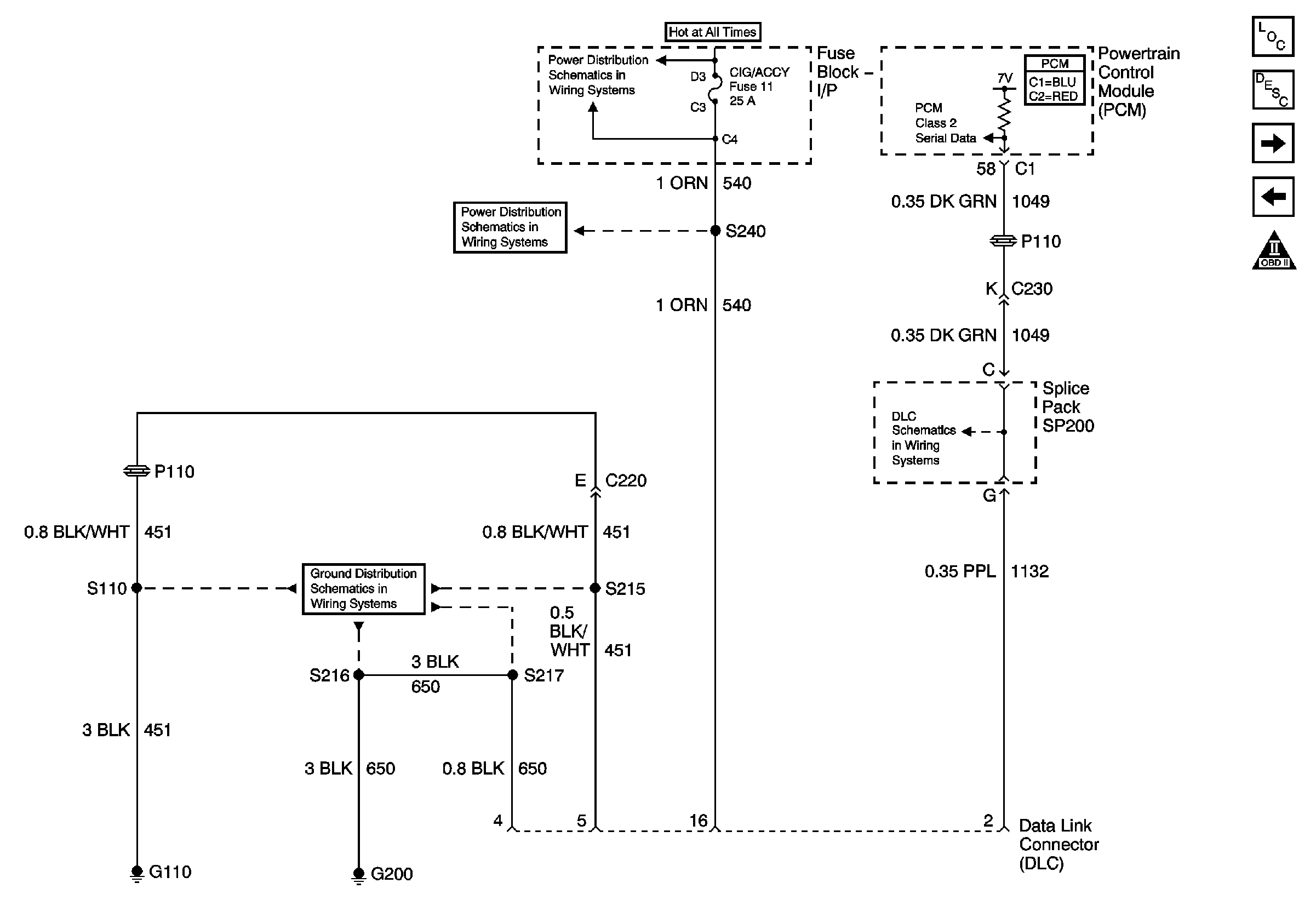
| Figure 3: |
Data Link Connector
|
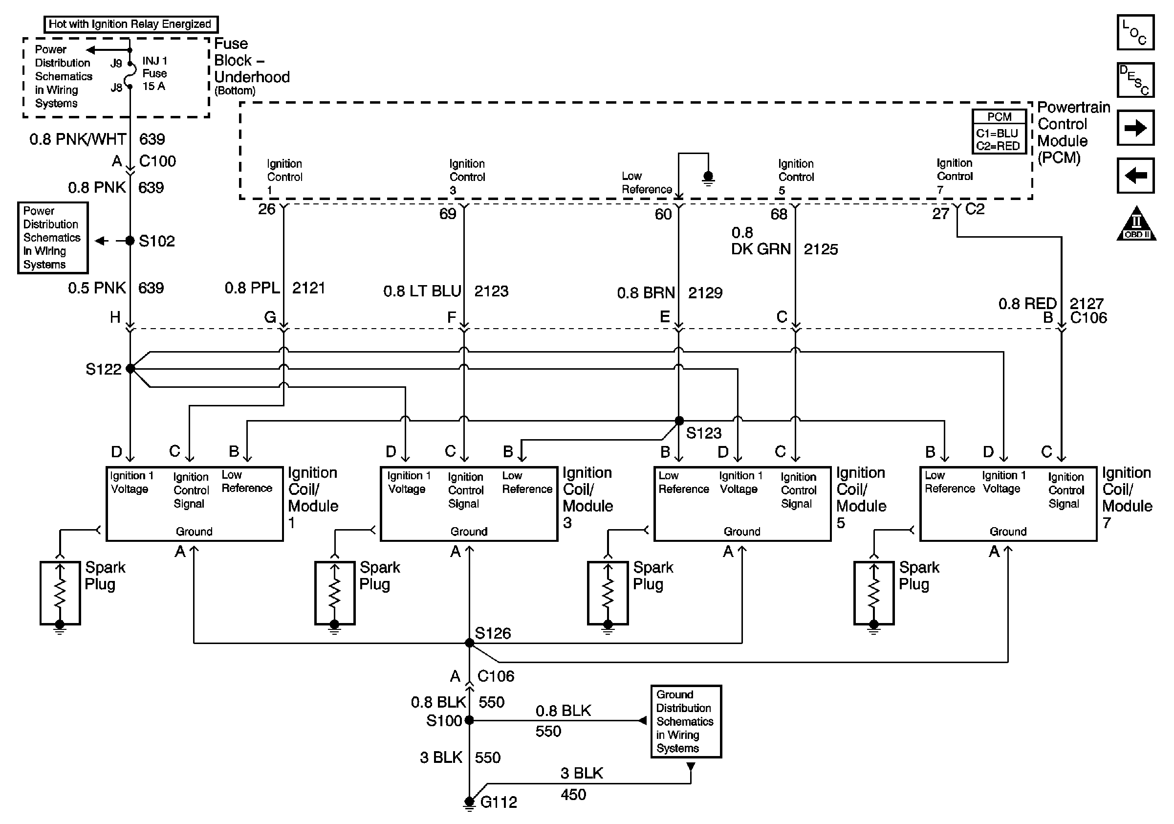
| Figure 4: |
Ignition Modules/Coils, Bank 1
|
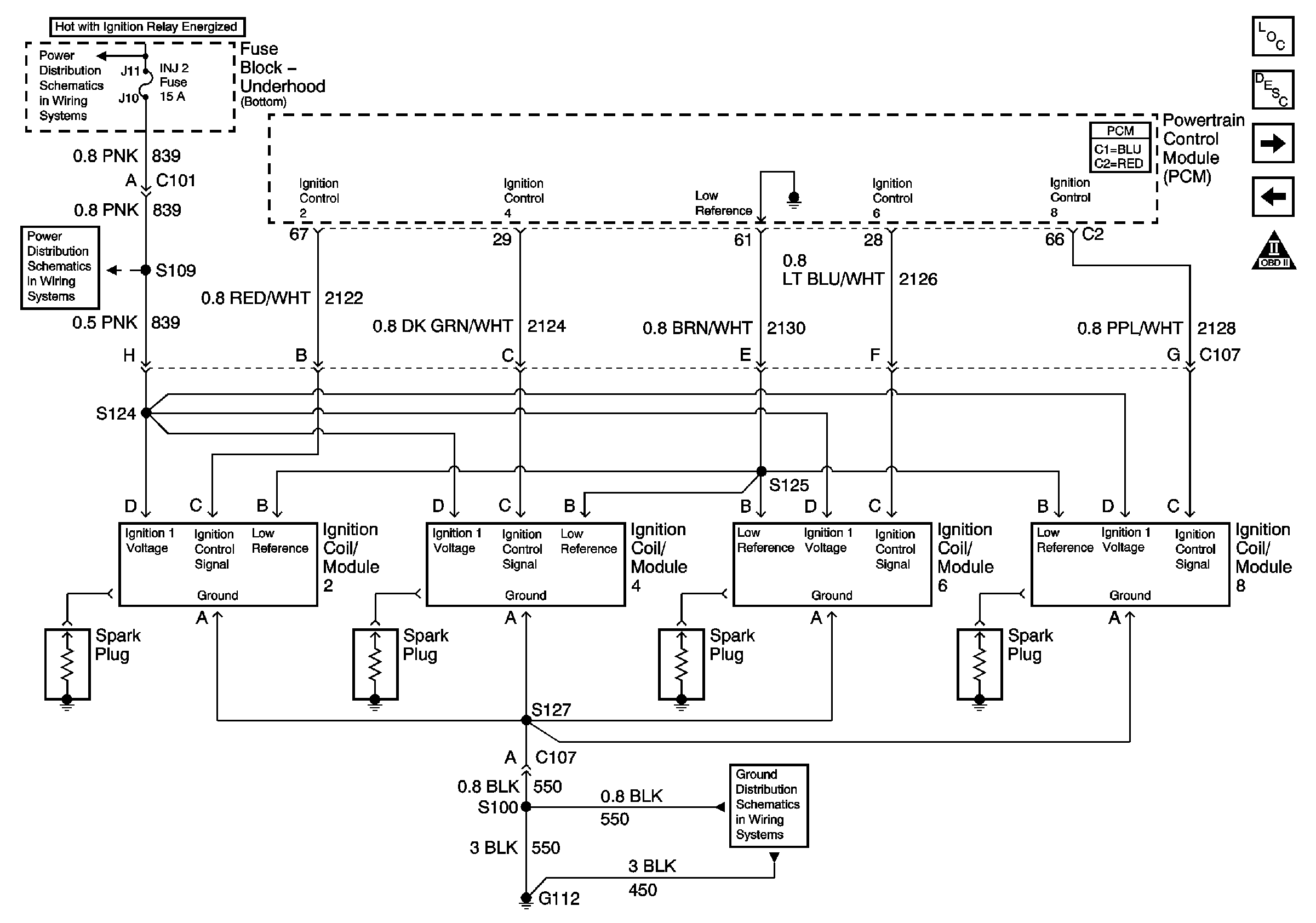
| Figure 5: |
Ignition Modules/Coils, Bank 2
|
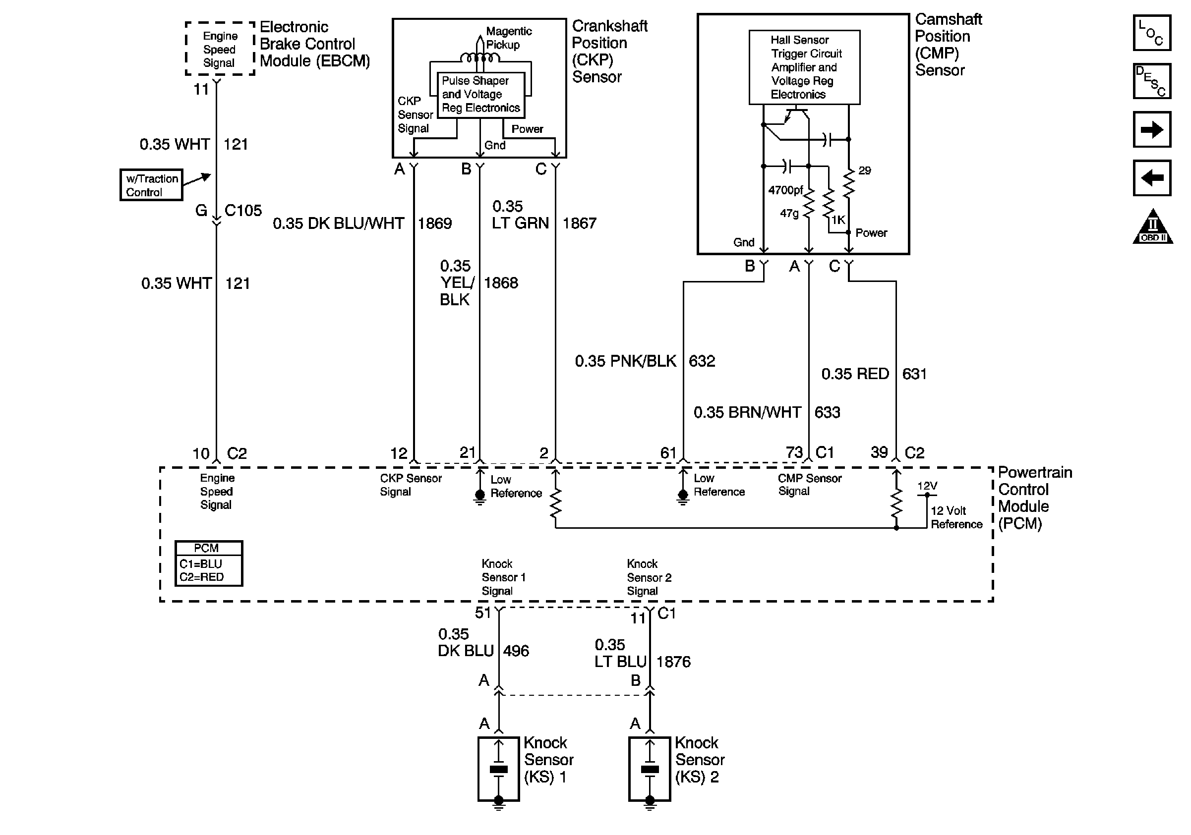
| Figure 6: |
Camshaft Position Sensor, Crankshaft Position Sensor, and Knock Sensors
|
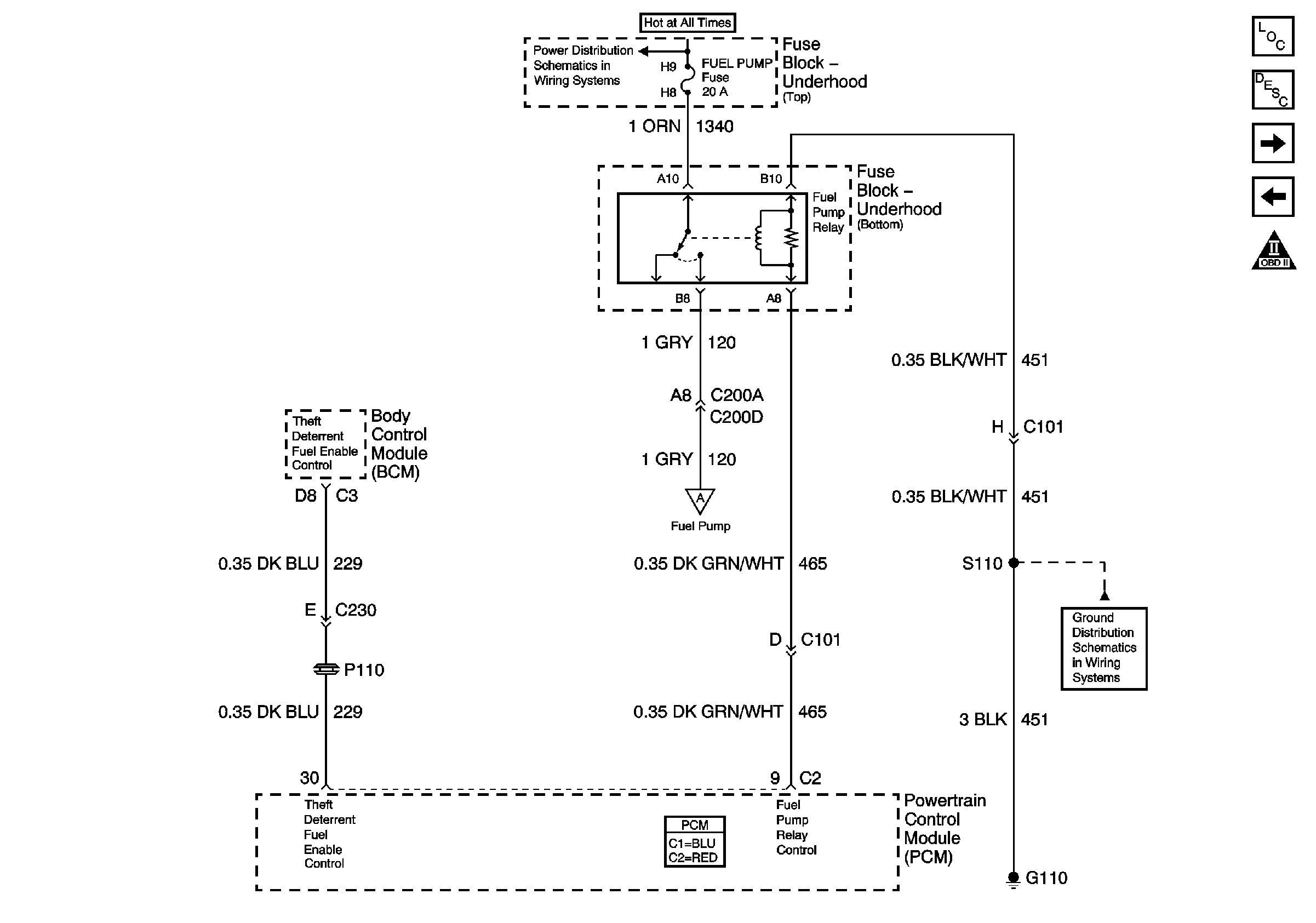
| Figure 7: |
BCM and Fuel Pump
|
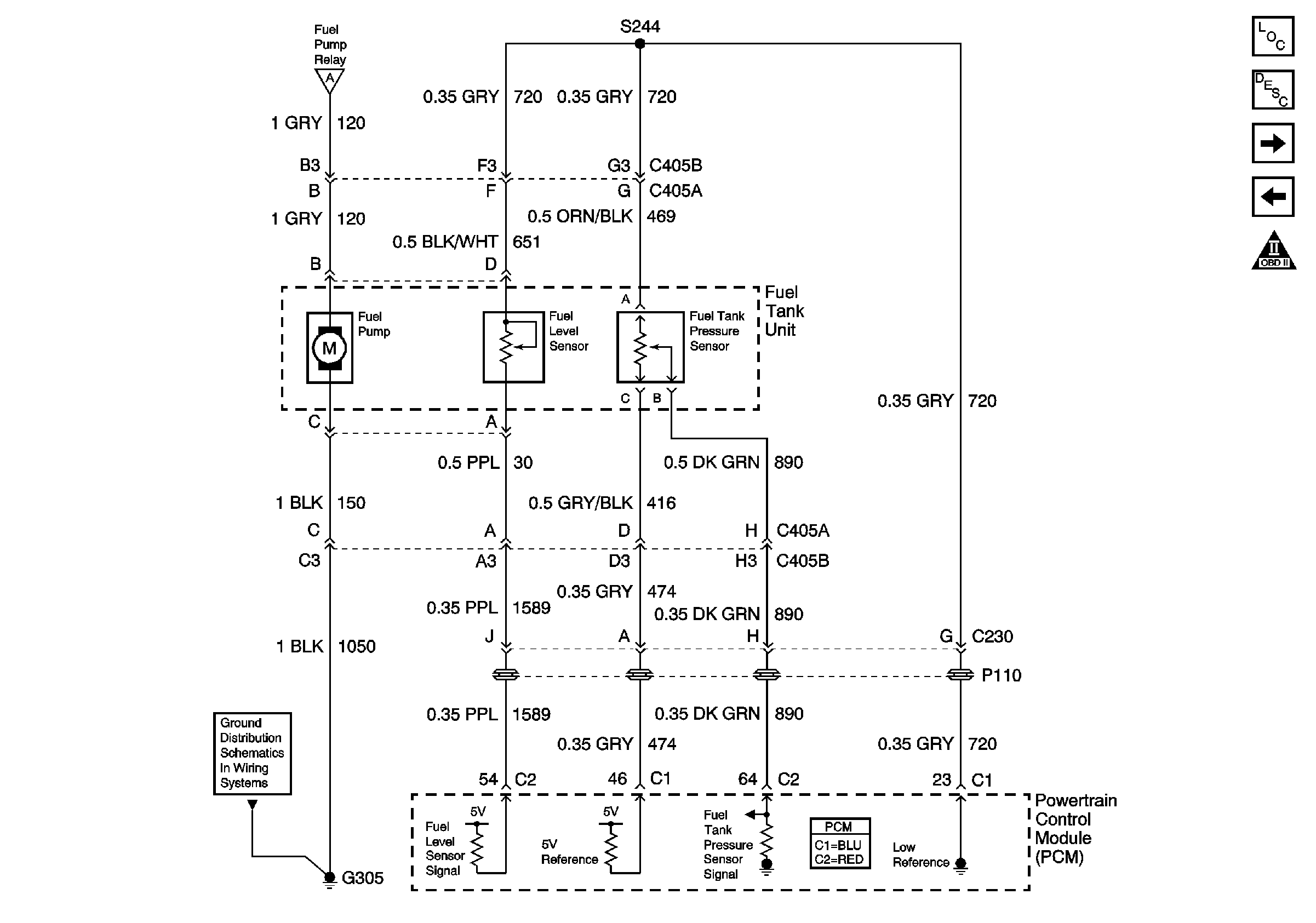
| Figure 8: |
Fuel Tank Unit
|
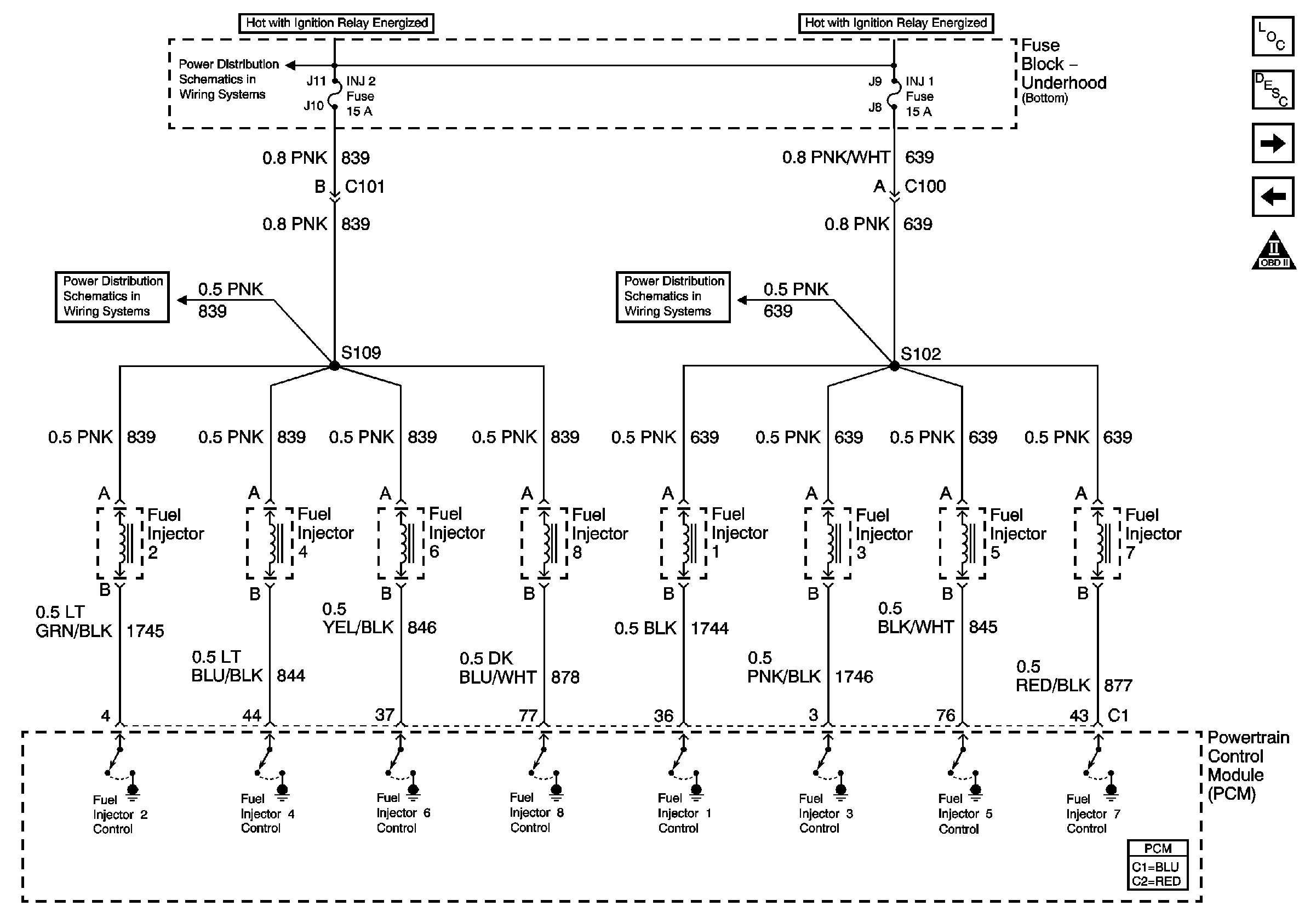
| Figure 9: |
Fuel Injectors
|
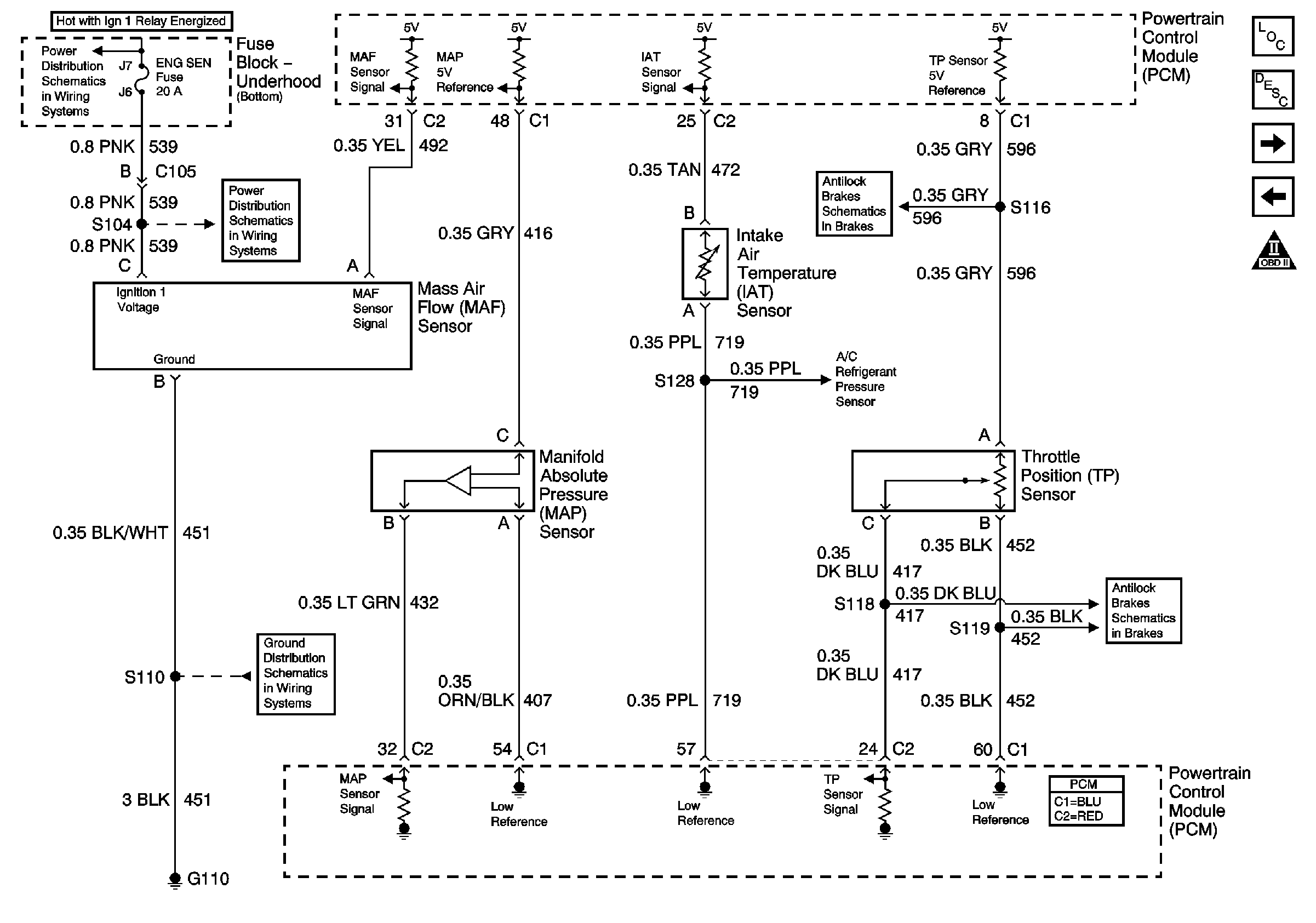
| Figure 10: |
Engine Sensors
|
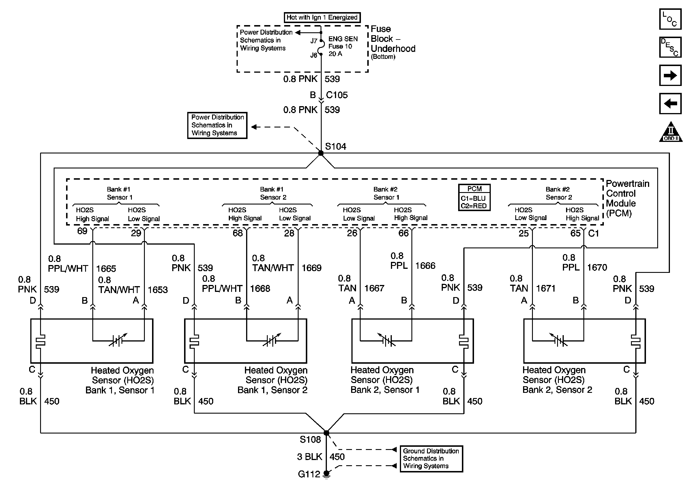
| Figure 11: |
Oxygen Sensors
|
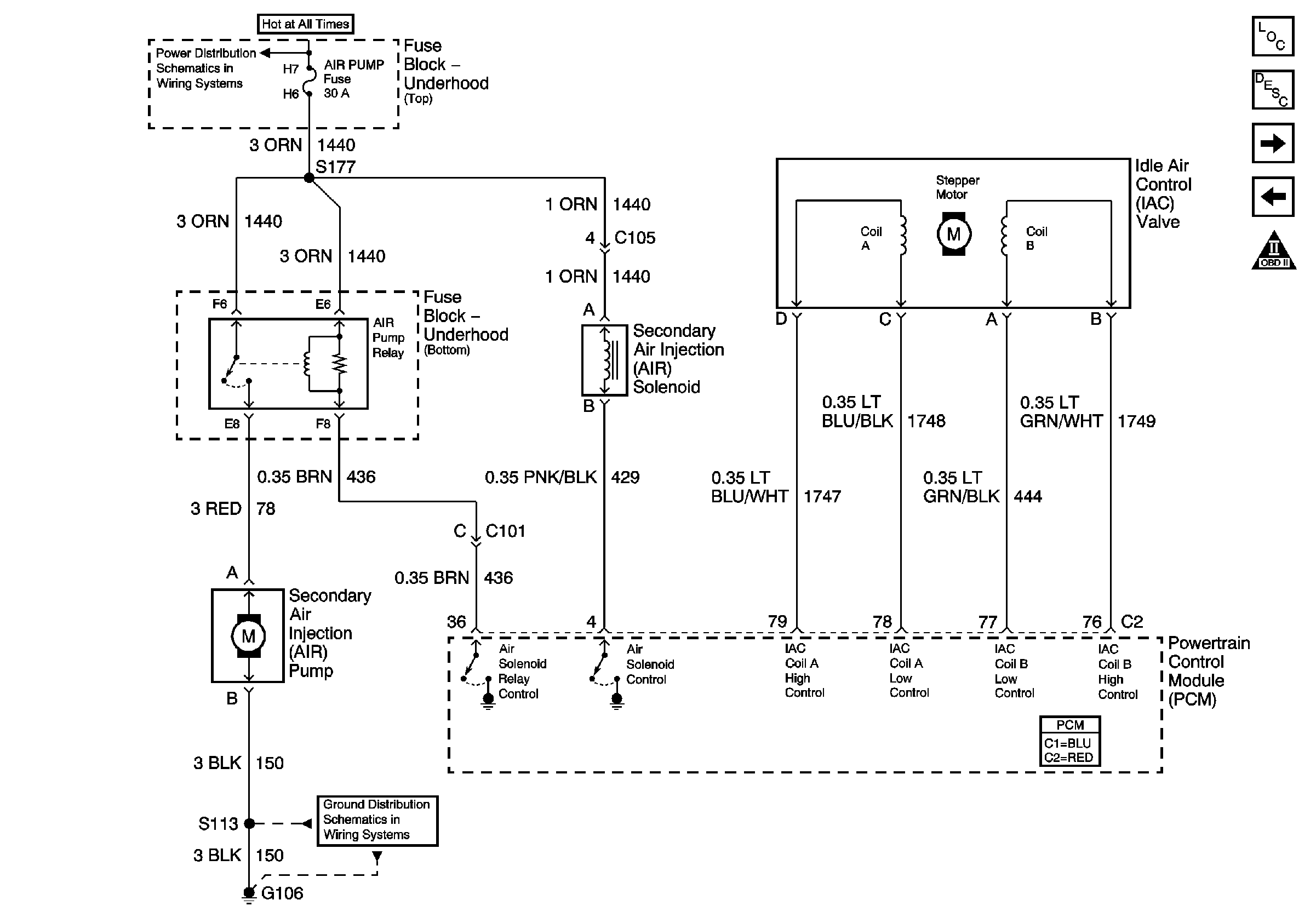
| Figure 12: |
AIR Pump and IAC
|
| Figure 13: |
BCM, Cruise Control Module, EBCM, IPC, Radio, and VSS
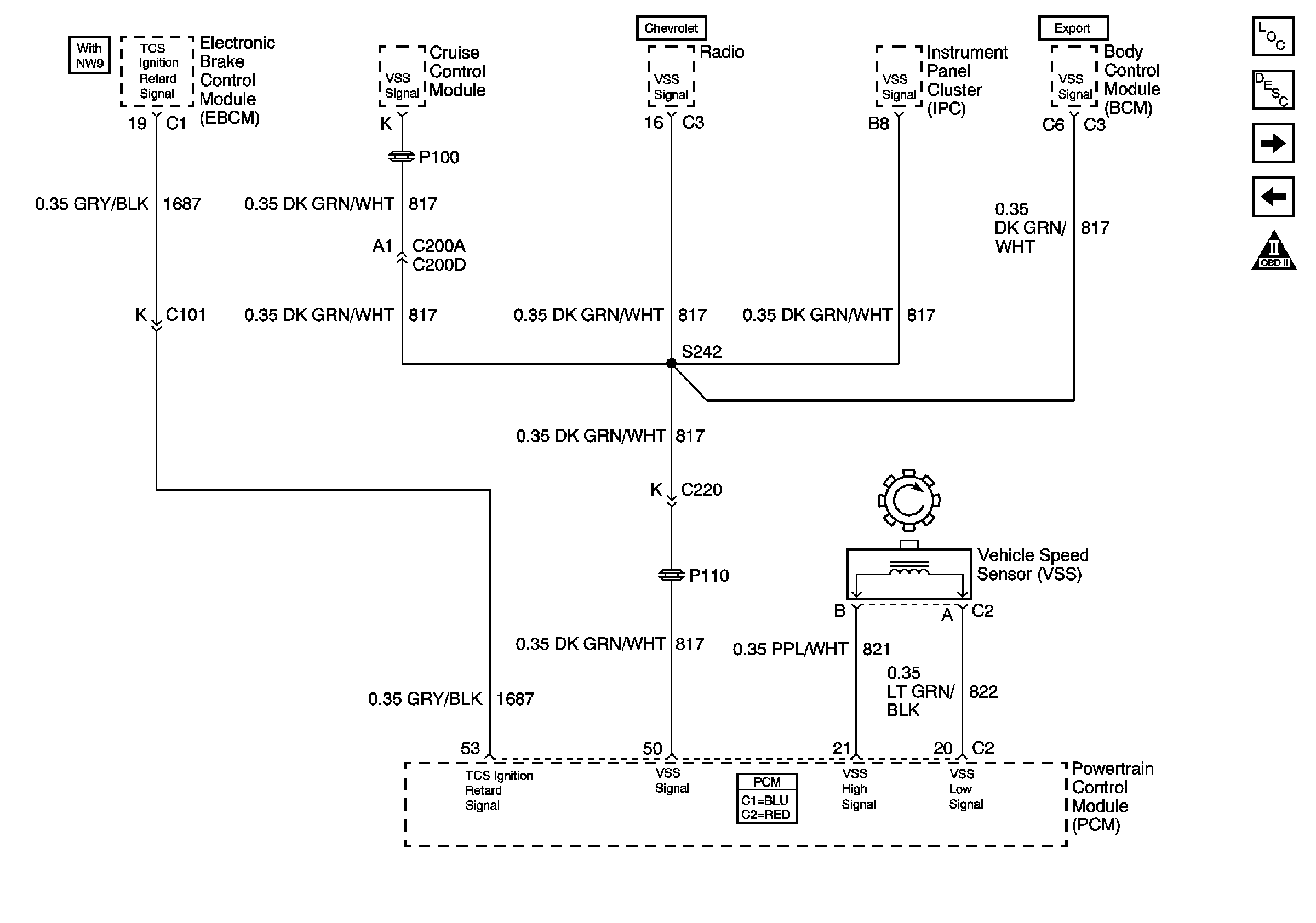
|
| Figure 14: |
EVAP
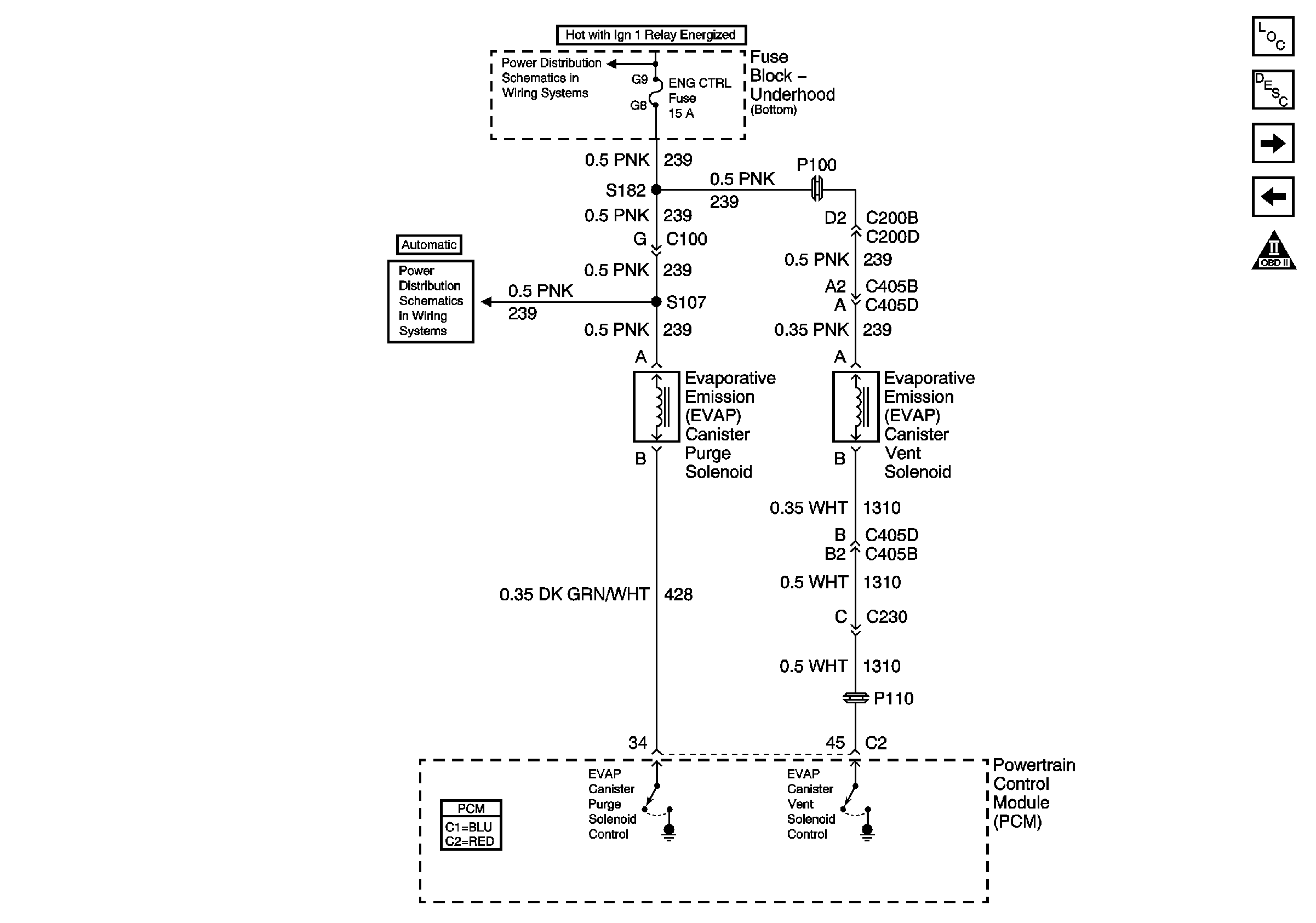
|
| Figure 15: |
Cruise Control Module, ECT Sensor, Engine Oil Level Switch and Generator
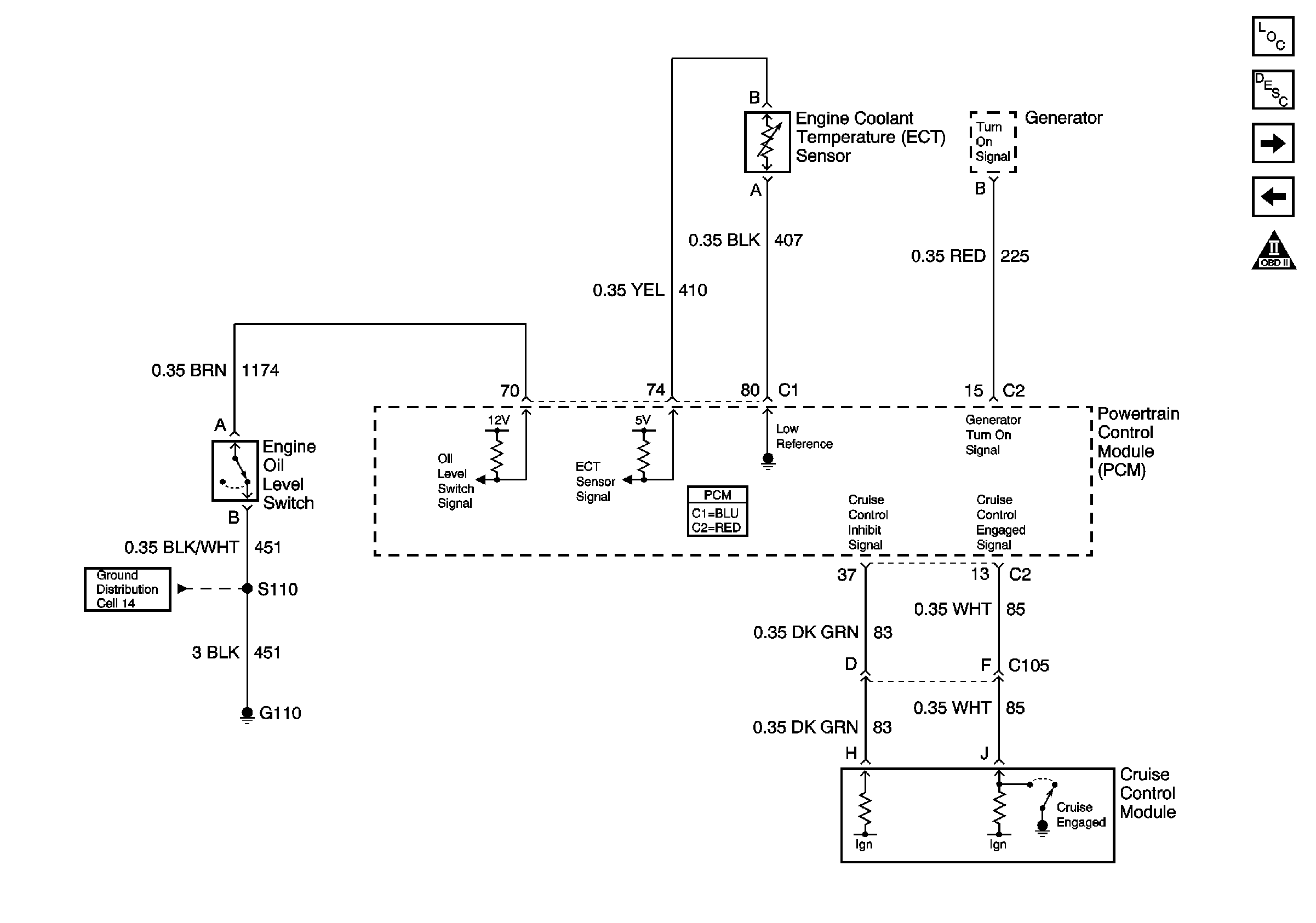
|
| Figure 16: |
Cruise Control Clutch Switch and Manual Transmission
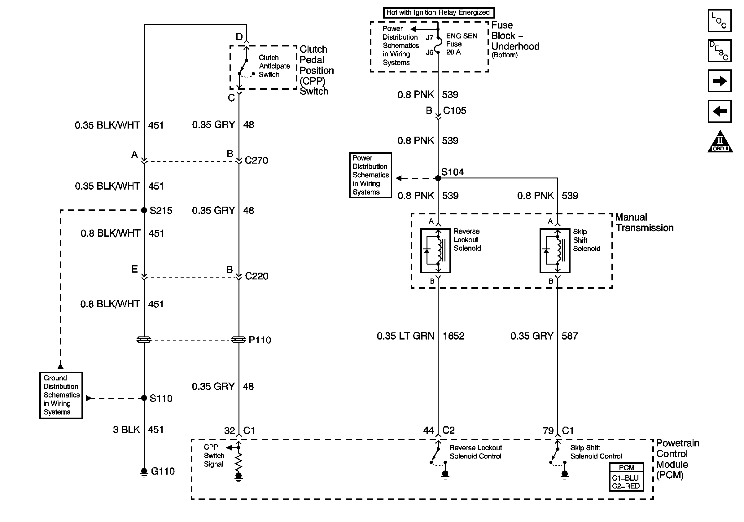
|
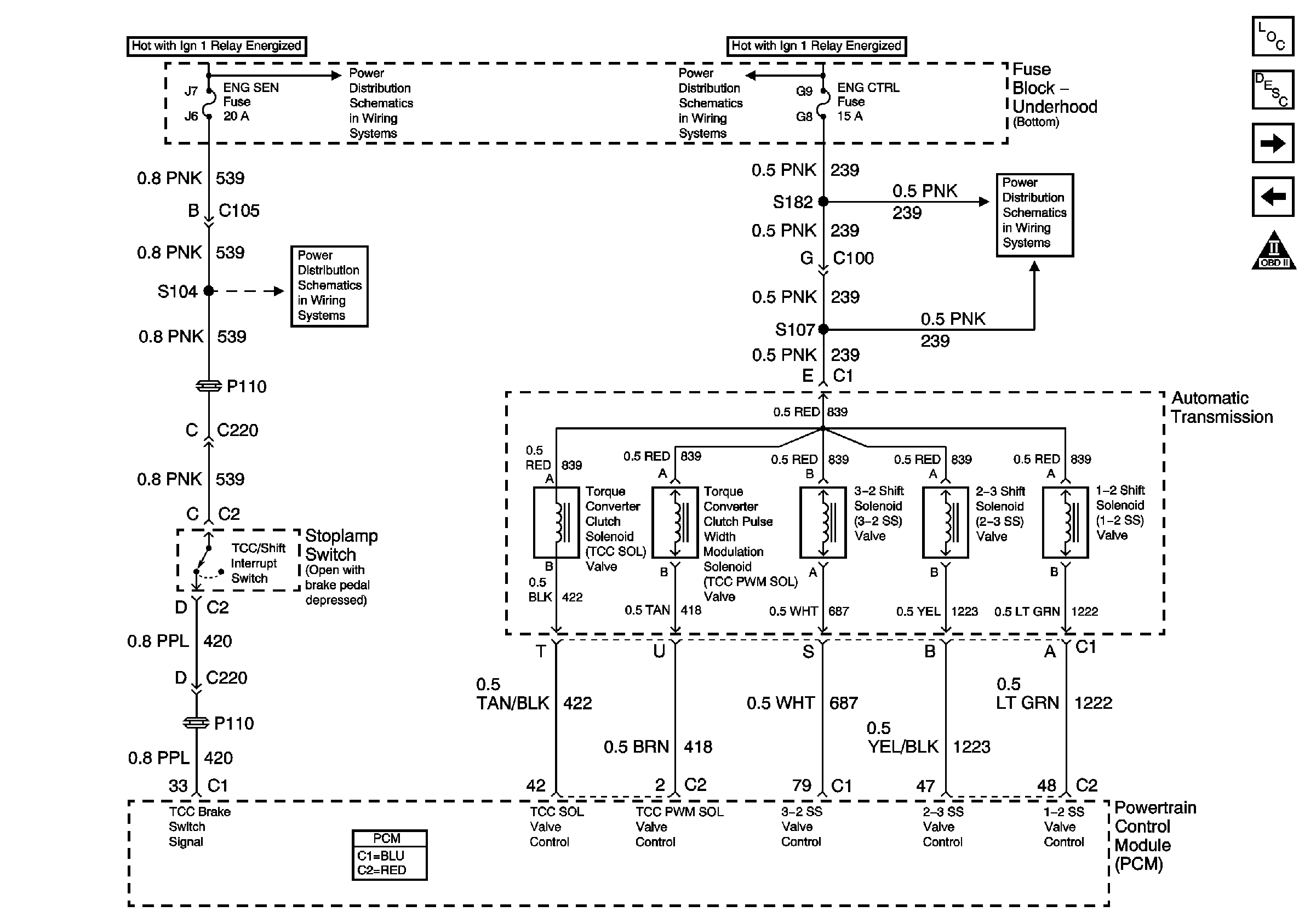
| Figure 17: |
Automatic Transmission and Stop Lamp Switch
|
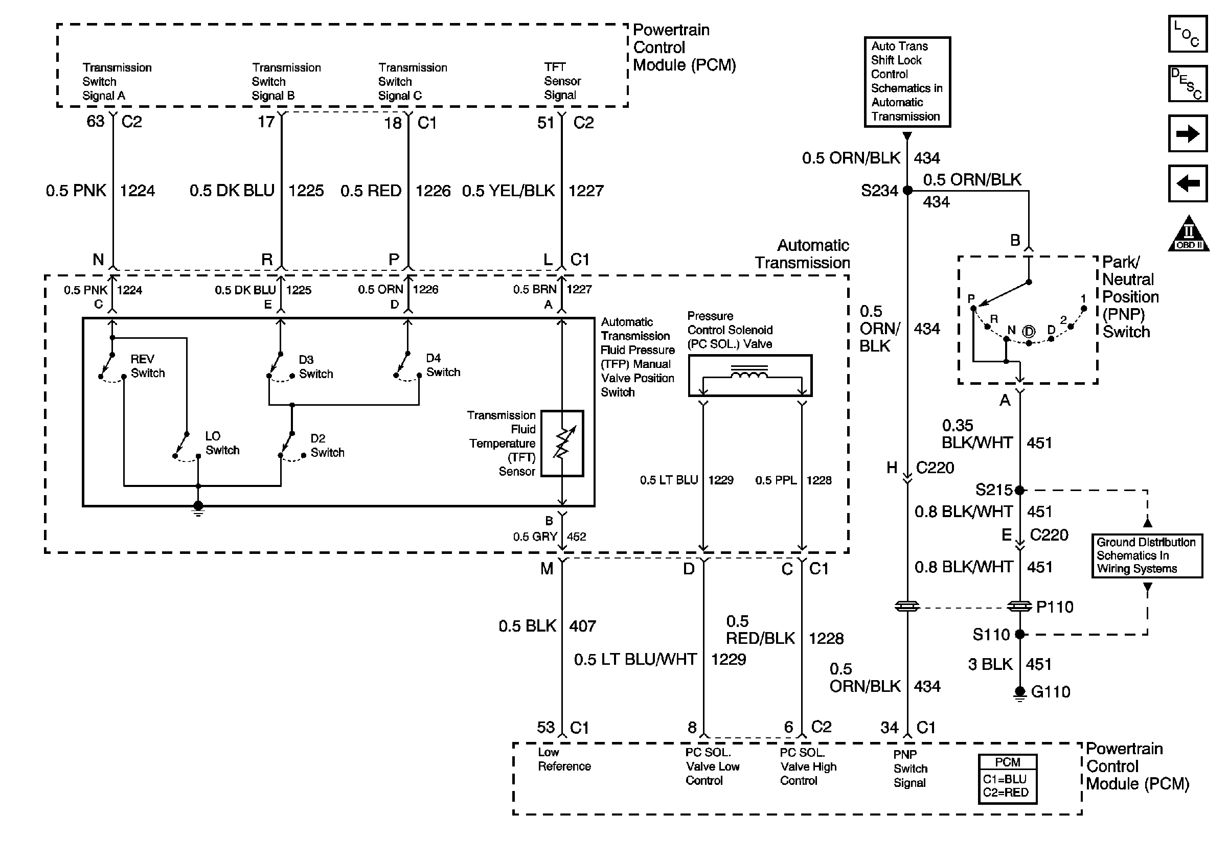
| Figure 18: |
Automatic Transmission and Park/Neutral Position Switch
|
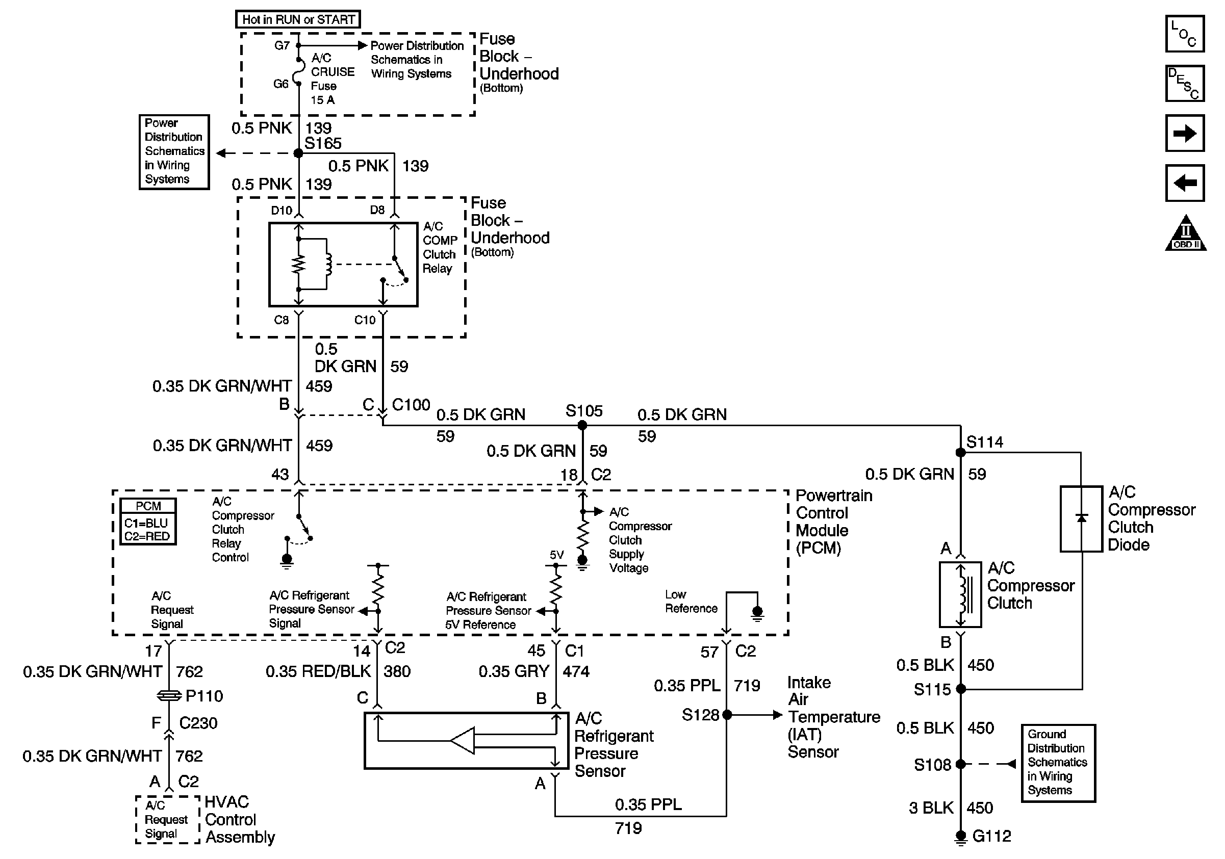
| Figure 19: |
A/C Compressor Control
|
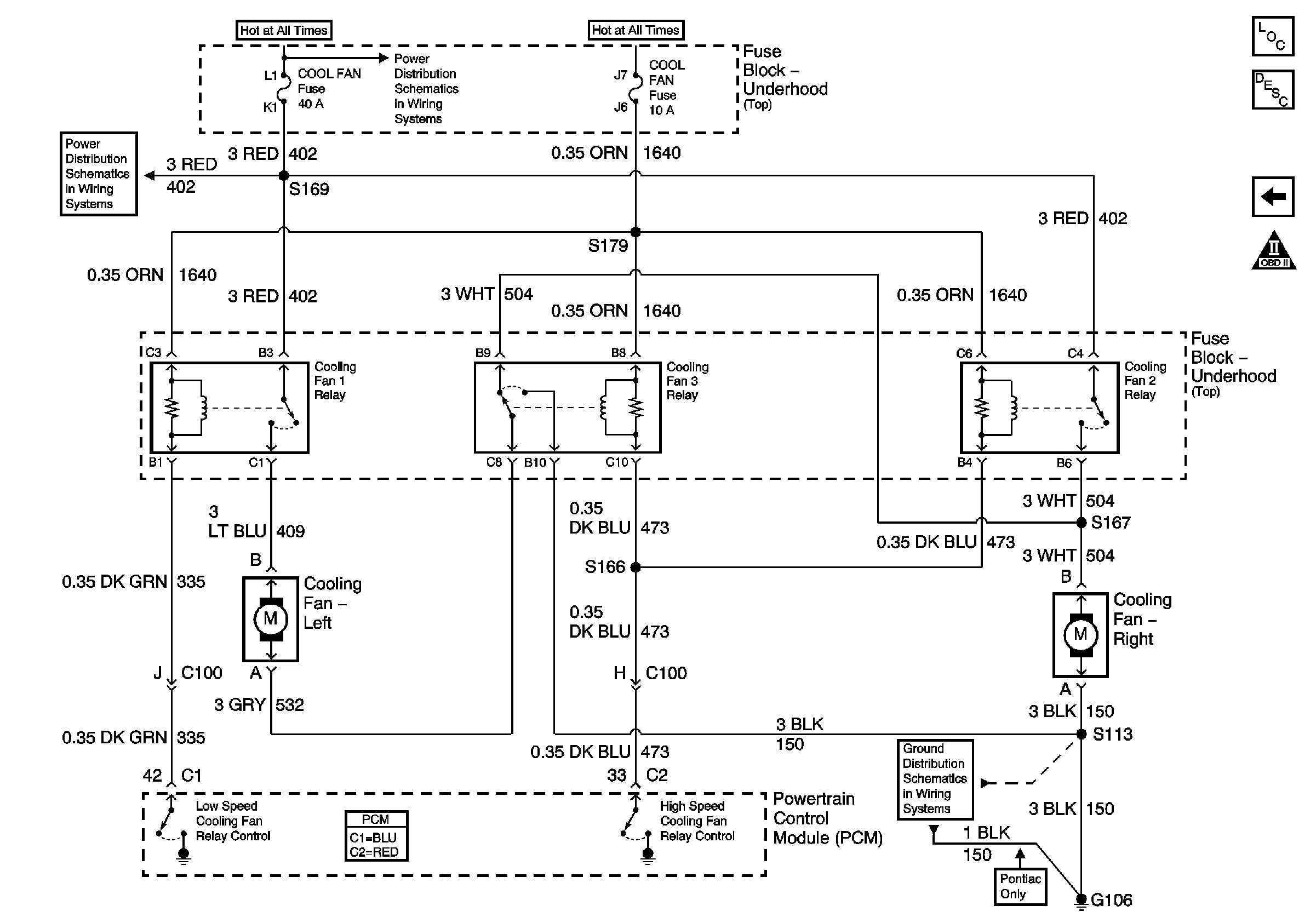
| Figure 20: |
Cooling Fans
|


