Removal Procedure
- Raise and support the vehicle. Refer to Lifting and Jacking the Vehicle in General Information.
- Remove the front tire and wheel assembly. Refer to Tire and Wheel Removal and Installation in Tires and Wheels.
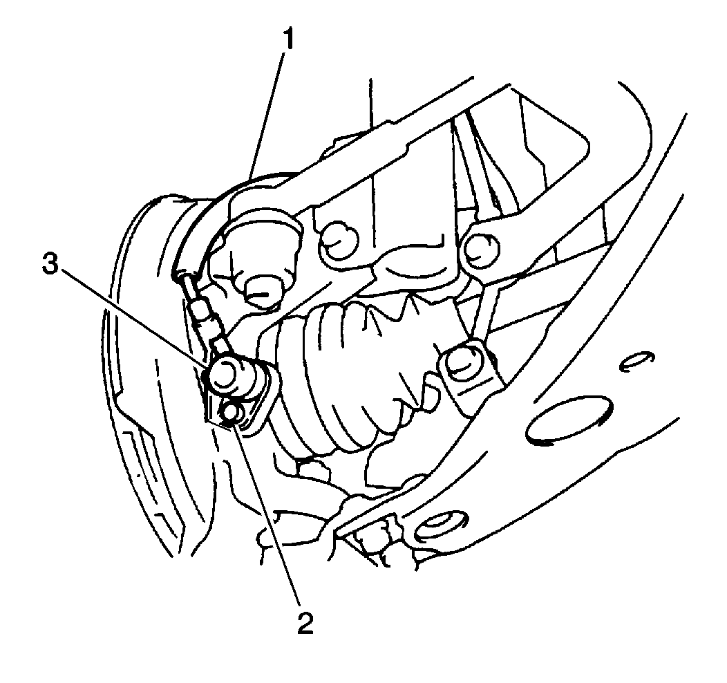
- Remove the 1 bolt (2) and the ABS speed sensor (3) from the steering knuckle, if necessary.
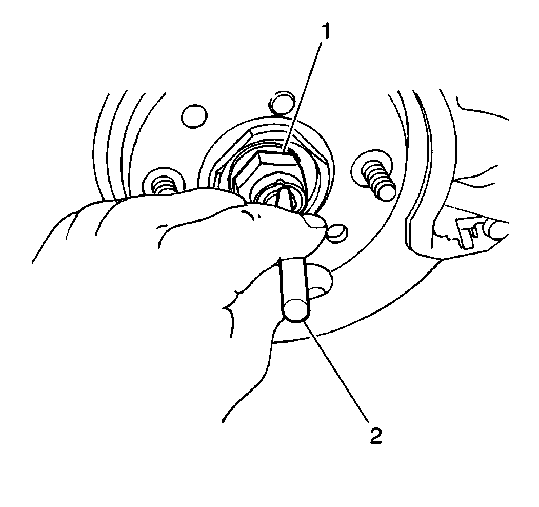
- Unstake the wheel drive shaft nut (1).
- Remove the wheel drive shaft nut and the washer.
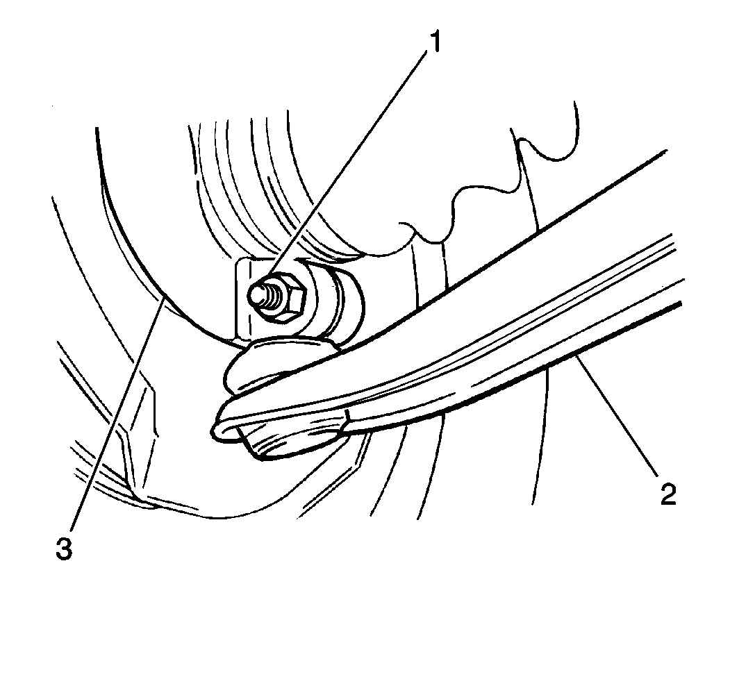
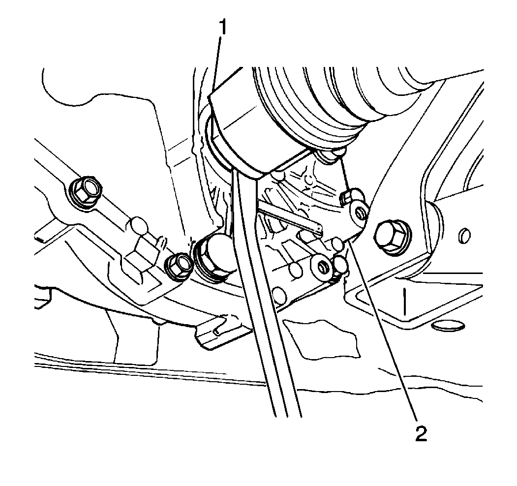
- Remove the ball stud bolt (1). The ball stud bolt is threaded into the steering knuckle (3).
- Separate the control arm (2) from the steering knuckle.
- Remove the right wheel drive shaft assembly (1) from the intermediate shaft bearing (2) by gently tapping with a plastic mallet.
- Remove the inner joint (1) from the transaxle (2) by gently prying the inner joint from the transaxle.
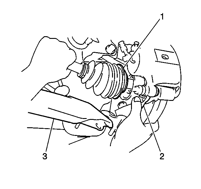
- Remove the outer joint (1) from the steering knuckle and the wheel drive shaft assembly from the vehicle.
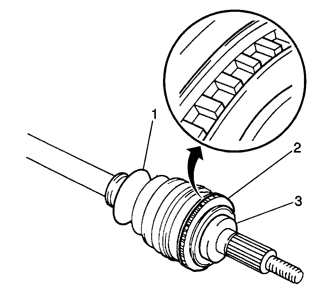
- Inspect the inner joint boots (1) and the outer joint boots for tears or for deterioration. Replace the boots, if necessary. Refer to Inner Joint and Seal Replacement or to Outer Joint and Seal Replacement .
- Inspect the inner oil seals and the outer oil seals on in the front wheel bearing for damage or for deterioration. Replace the seals, if necessary. Refer to Front Wheel Bearing and Hub Replacement in Front Suspension.
- Inspect the fluid seals of the wheel drive shaft at the transaxle for leakage or for damage. Replace the fluid seals, if necessary. Refer to Drive Axle Shaft Fluid Seal in Automatic Transmission or to Axle Shaft Oil Seal Replacement in Manual Transmission.
Caution: To prevent personal injury and/or component damage, do not allow the weight of the vehicle to load the front wheels, or attempt to operate the vehicle, when the wheel drive shaft(s) or wheel drive shaft nut(s) are removed. To do so may cause the inner bearing race to separate, resulting in damage to brake and suspension components and loss of vehicle control.
Notice: Refer to Wheel Drive Shaft Damage Notice in the Preface section.
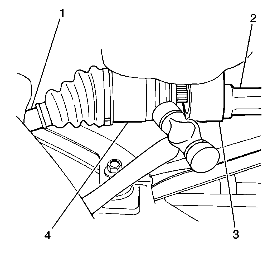
Important: On the manual transmission model, an intermediate shaft (2) between the inner joint (4) and the transaxle stabilizes the right wheel drive shaft assembly. It is not necessary to remove the intermediate shaft.
Notice: Refer to Wheel Drive Shaft Handling Notice in the Preface section.
Notice: When servicing the hub assembly, be careful not to damage the ABS components. If any of the ABS components are damaged, the ABS system may not function properly and the damaged component will need to be replaced.
Installation Procedure
- Install the outer joint (1) into the steering knuckle.
- Install the inner joint into the transaxle or into the intermediate shaft.
- Install the control arm (2) to the steering knuckle.
- Install the ball stud bolt. The ball stud bolt is threaded into the steering knuckle.
- Install the wheel drive shaft washer and the nut (1) onto the wheel drive shaft.
- Stake the wheel drive shaft nut (1).
- Install the ABS speed sensor (3) into the steering knuckle, if necessary.
- Install the front tire and wheel assembly. Refer to Tire and Wheel Removal and Installation in Tires and Wheels.
- Lower the vehicle.
- Check the transaxle fluid level. Refer to Transmission Fluid Check in Automatic Transmission or to Transmission Fluid Check in Manual Transmission.


Notice: Use the correct fastener in the correct location. Replacement fasteners must be the correct part number for that application. Fasteners requiring replacement or fasteners requiring the use of thread locking compound or sealant are identified in the service procedure. Do not use paints, lubricants, or corrosion inhibitors on fasteners or fastener joint surfaces unless specified. These coatings affect fastener torque and joint clamping force and may damage the fastener. Use the correct tightening sequence and specifications when installing fasteners in order to avoid damage to parts and systems.
Tighten
Tighten the ball stud bolt to 60 N·m (44 lb ft).

Tighten
Tighten the wheel drive shaft nut to 175 N·m (129 lb ft).

Tighten
Tighten the ABS speed sensor bolt (2) to 10 N·m (8 lb ft).
