Removal Procedure
- Disconnect the battery ground cable from the battery. Refer to Battery Negative Cable Disconnection and ConnectionBattery Negative Cable Disconnection and Connection .
- Disable the SIR system. Refer to SIR Disabling and EnablingSIR Disabling and Enabling .
- Remove the I/P compartment. Refer to Instrument Panel Compartment ReplacementInstrument Panel Compartment Replacement .
- Remove the trim panel - (I/P) Upper. Refer to Instrument Panel Upper Trim Panel ReplacementInstrument Panel Upper Trim Panel Replacement
- Remove the outer trim cover. Refer to Instrument Panel Outer Trim Cover ReplacementInstrument Panel Outer Trim Cover Replacement .
- Remove the ventilation trim panel. Refer to Instrument Panel Side Trim Panel ReplacementInstrument Panel Side Trim Panel Replacement .
- Remove the trim plate - console side. Refer to Front Floor Console Side Trim Panel Replacement - Right SideFront Floor Console Side Trim Panel Replacement - Right Side .
- Remove the instrument panel trim panel. Refer to Instrument Panel Trim Panel ReplacementInstrument Panel Trim Panel Replacement .
- Remove the instrument cluster. Refer to Instrument Cluster ReplacementInstrument Cluster Replacement .
- Remove the defroster grill. Refer to Defroster Grille ReplacementDefroster Grille Replacement .
- Remove the knee bolster. Refer to Knee Bolster ReplacementKnee Bolster Replacement .
- Remove the instrument panel center trim panel. Refer to Instrument Panel Center Trim Panel ReplacementInstrument Panel Center Trim Panel Replacement .
- Remove the I/P centre speaker. Refer to Radio Front Speaker ReplacementRadio Front Speaker Replacement .
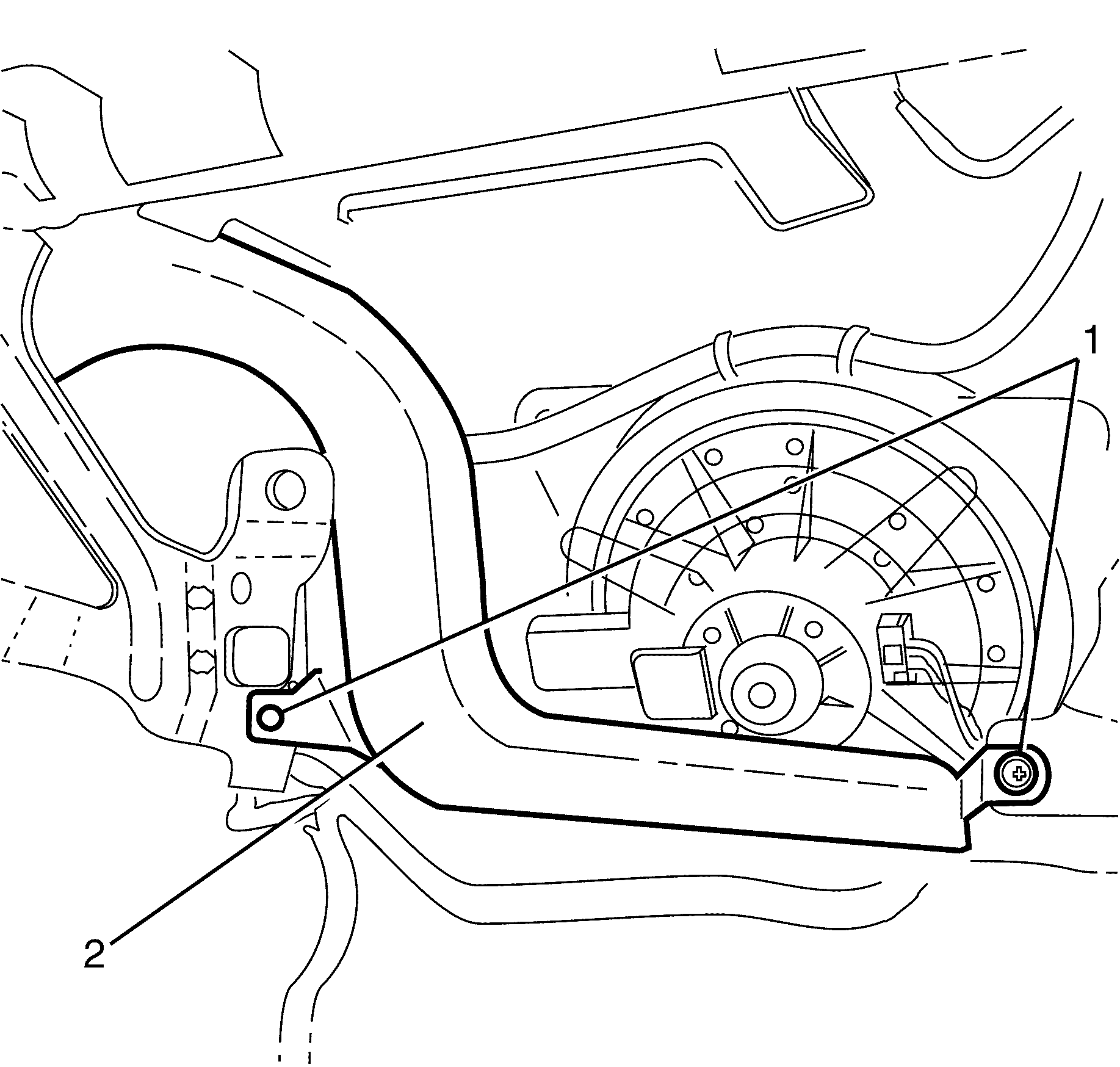
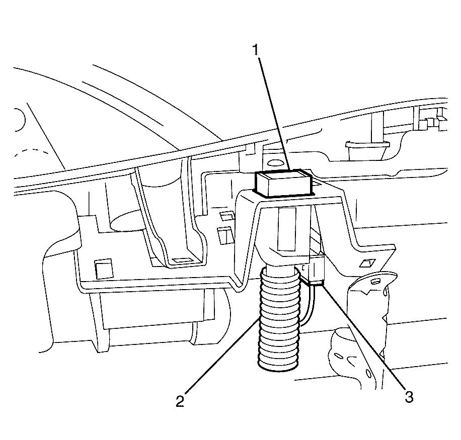
- Remove the lower air duct retaining clips (1).
- Remove the lower air duct (2).
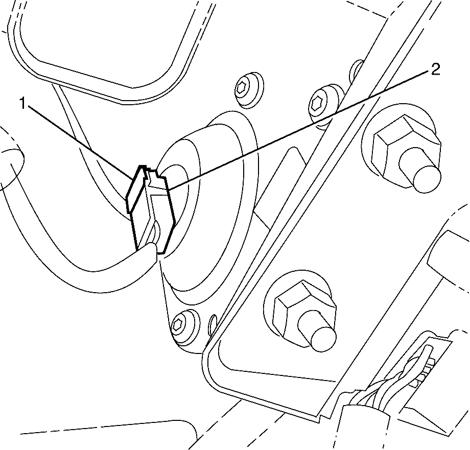
- Release the air bag electrical connector retaining clip (1) and disconnect the electrical connector (2).
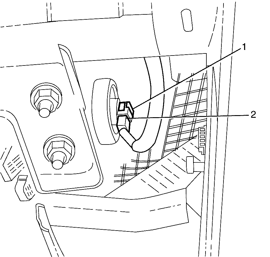
- Release the air bag electrical connector retaining clip (1) and disconnect the electrical connector (2).
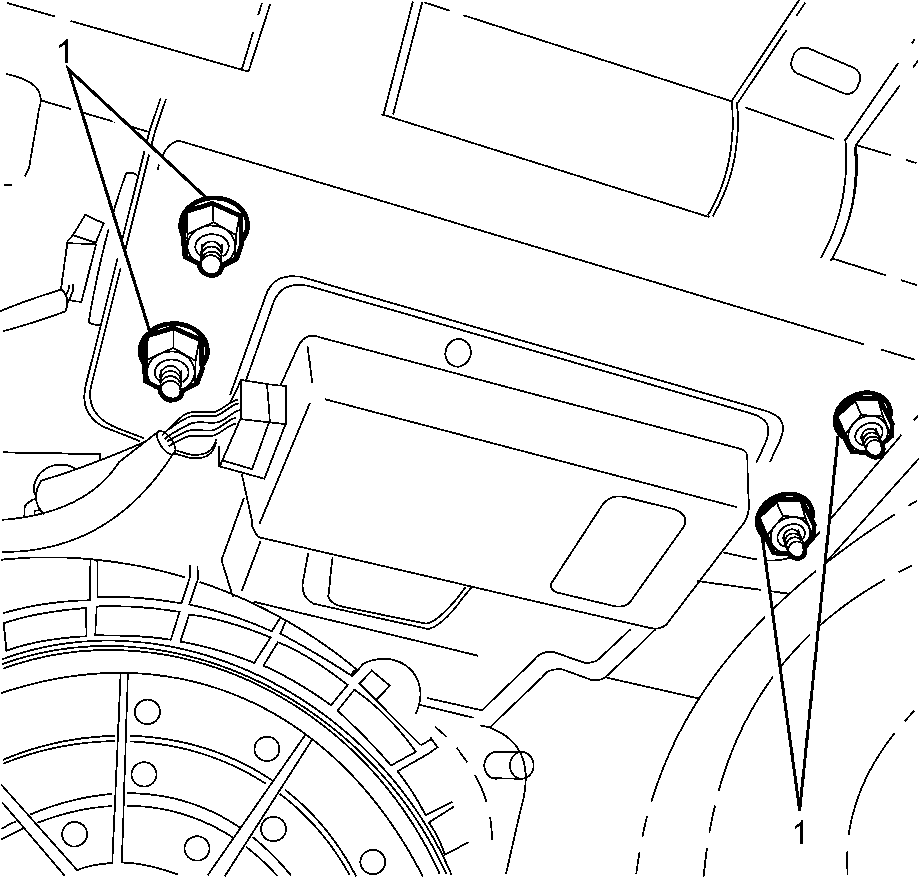
- Remove the air bag to I/P trim pad retaining nuts (1).
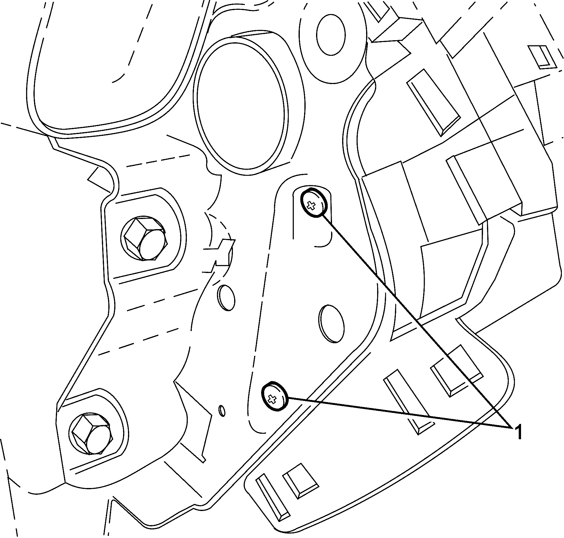
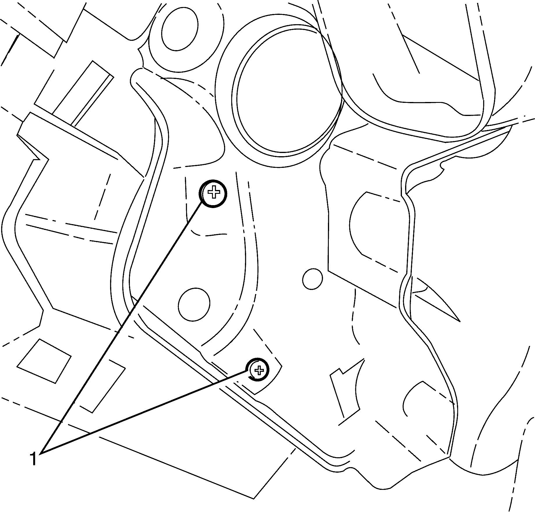
- Remove the I/P carrier to I/P pad outer retaining screws (1).
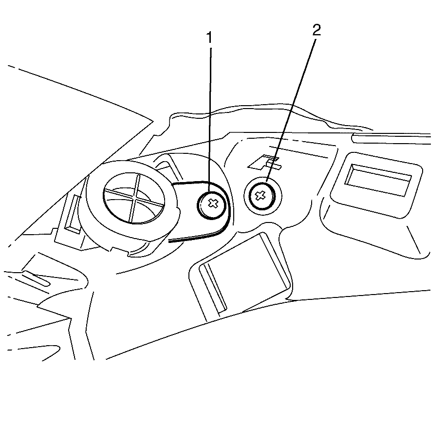
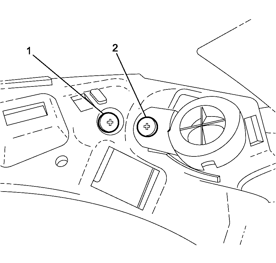
- Remove the left hand tweeter to I/P pad retaining screw (1).
- Remove the I/P pad retaining screw (2).
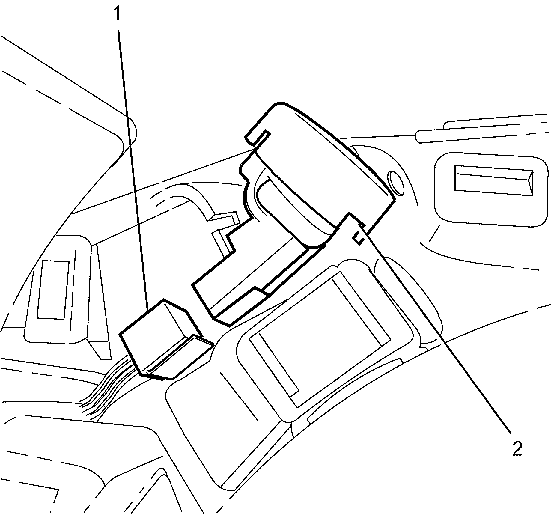
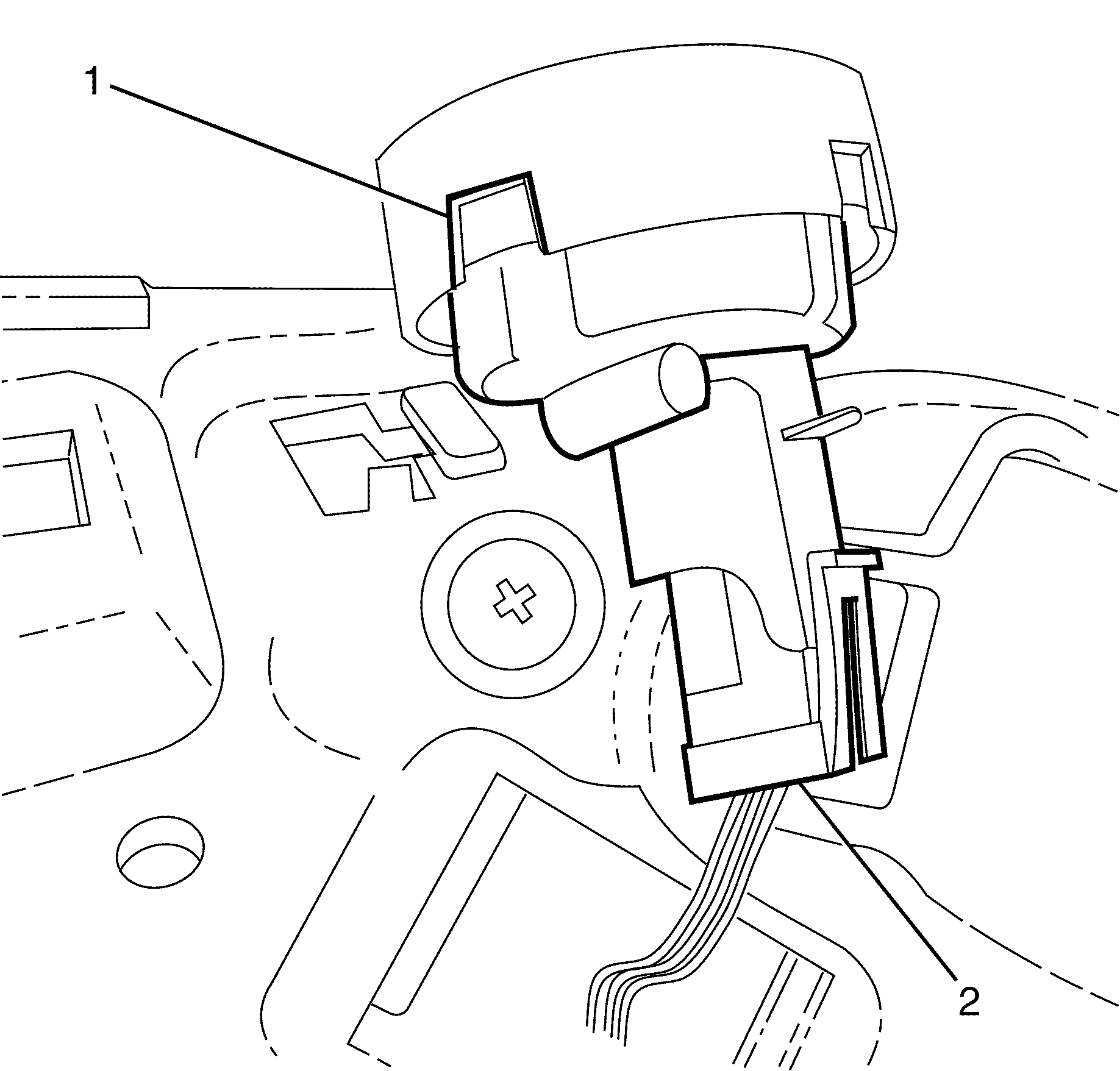
- Disconnect the left hand tweeter electrical connector (1).
- Remove the left hand tweeter (2).
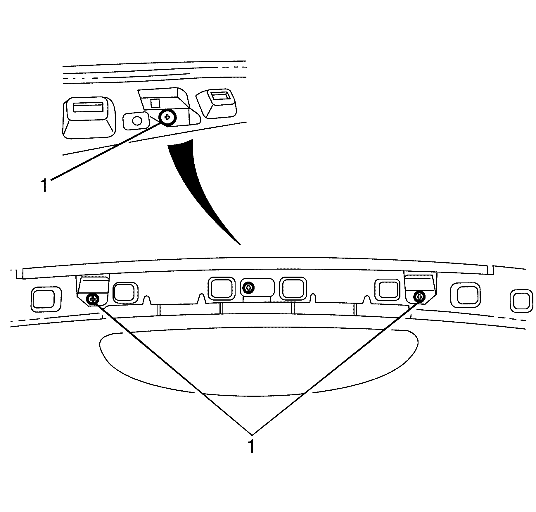
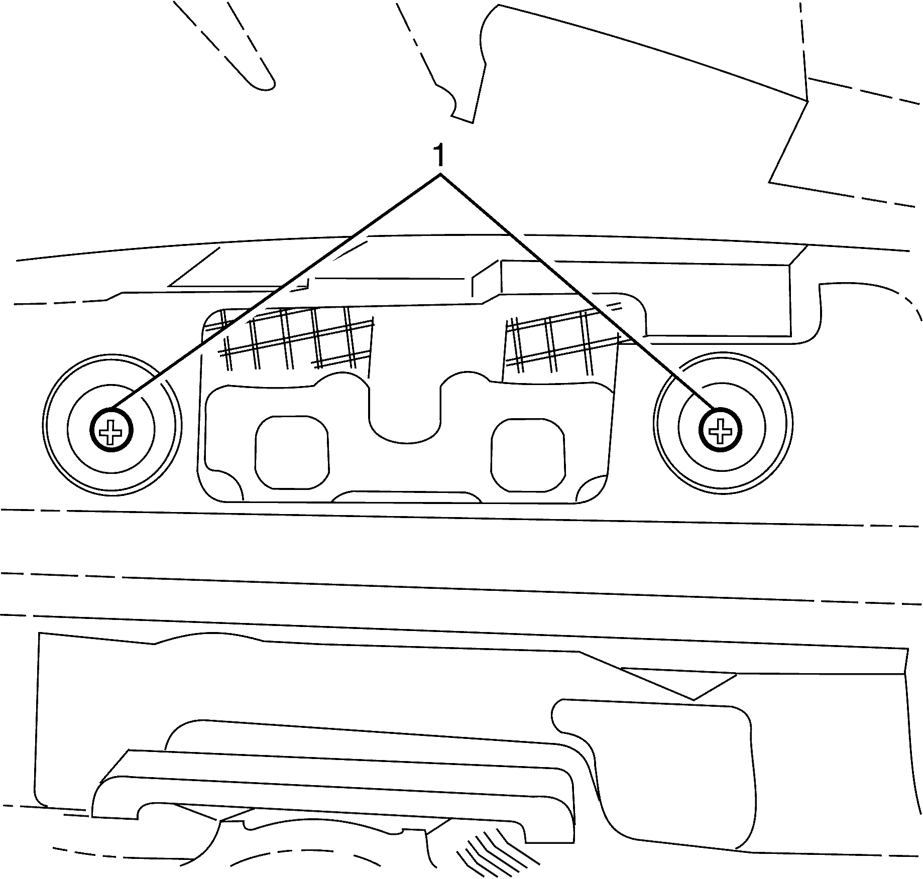
- Remove the top I/P pad to I/P carrier retaining screws (1).
- Remove the right hand tweeter to I/P pad retaining screw (2).
- Remove the I/P pad to I/P carrier retaining screw (1).
- Disconnect the right hand tweeter electrical connector (2).
- Remove the right hand tweeter (1).
- Remove the I/P carrier to I/P pad outer retaining screws (1).
- Remove the instrument cluster housing to I/P pad retaining screws (1).
- Remove the aspirator tube (2) from the rear of the inside air temperature sensor (1).
- Disconnect the inside air temperature sensor electrical connector (3).
- Remove the inside air temperature sensor (3) from the instrument panel carrier (2).
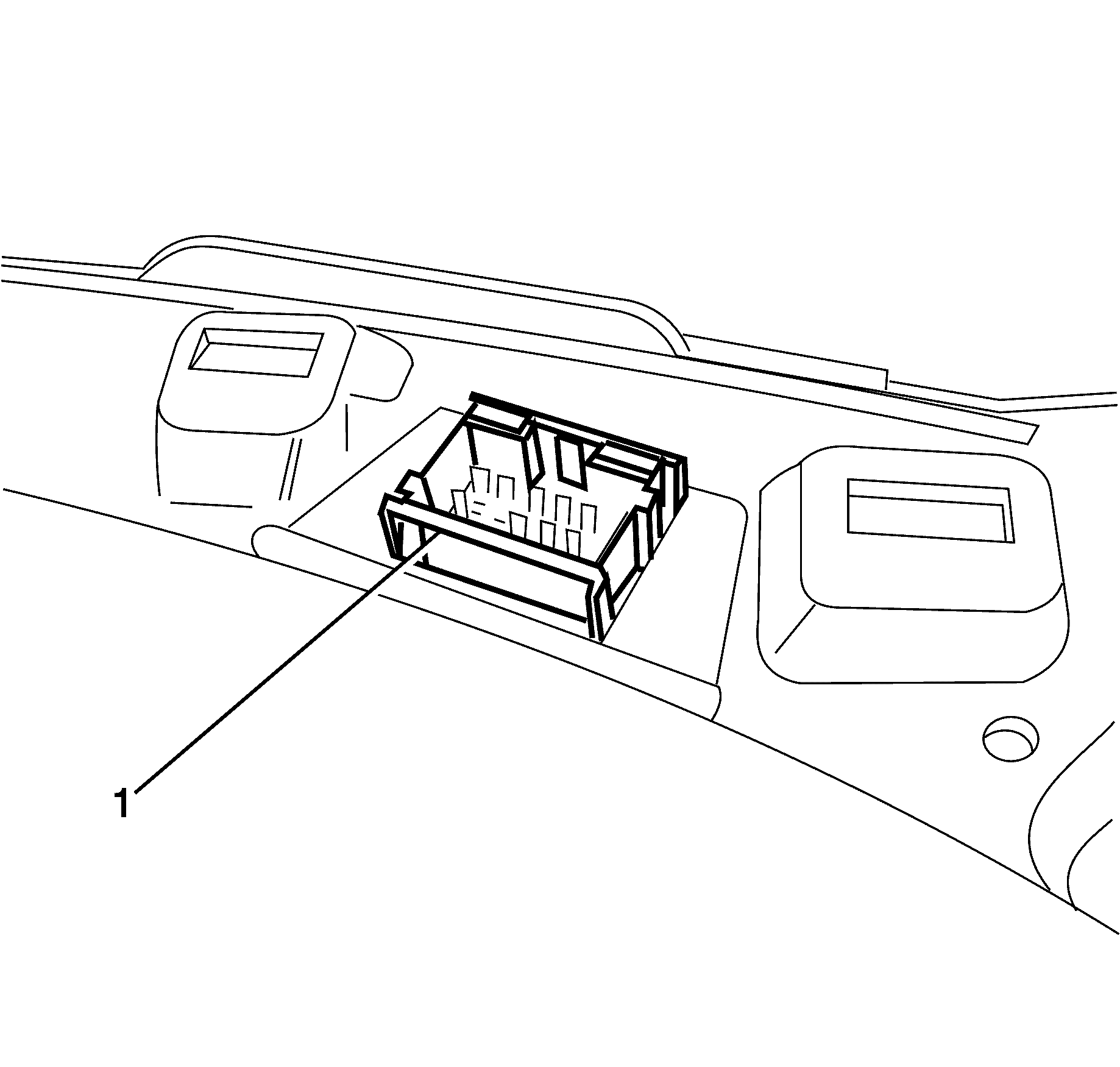
- Detach the headliner main wiring harness connector (1).
- With the aid of an assistant remove the I/P pad (1).
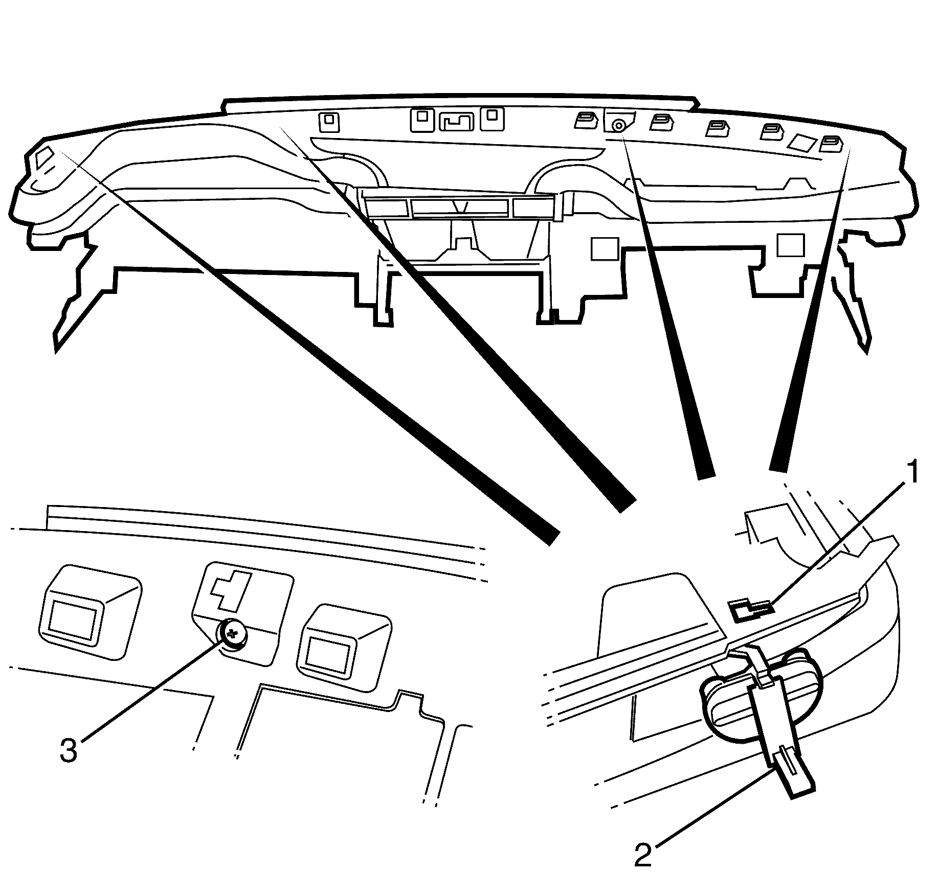
- Place the I/P pad (1) on a clean and suitable work surface.
- Remove the four datum pins (2) from the I/P pad (1).
Caution: Refer to Battery Disconnect Caution in the Preface section.
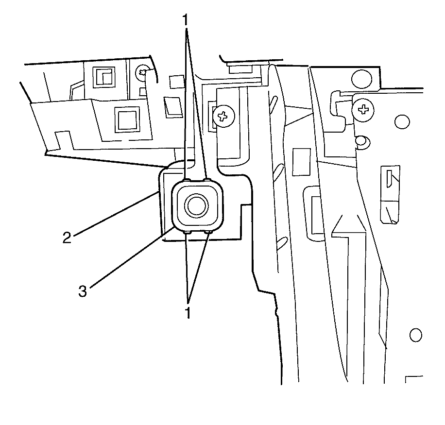
Important: From the front of the inside air temperature sensor (3) use a suitable tool to push down on the four inside air temperature sensor to instrument panel carrier retaining clips (1). Withdraw the inside air temperature sensor (1) rearwards towards the bulkhead from the instrument panel carrier (3) .
Installation Procedure
- Place the I/P pad on a clean and suitable work surface.
- Install the four datum pins (2) to the I/P pad (1).
- Secure the datum pins (2) using the datum pin retaining screws (3).
- Install the I/P pad (1) to the vehicle.
- Secure the headliner main wiring harness connector (1).
- Install the inside air temperature sensor (3) to the instrument panel carrier (2).
- Connect the inside air temperature sensor electrical connector (3).
- Install the aspirator tube (2) to the rear of the inside air temperature sensor (1).
- Install the Instrument cluster to I/P pad retaining screws (1).
- Install the I/P carrier to I/P pad outer retaining screws (1).
- Connect the right hand tweeter electrical connector (2).
- Install the right hand tweeter (1).
- Install the right hand tweeter to I/P pad retaining screw (2).
- Install the I/P pad to I/P carrier retaining screw (1).
- Install the top I/P pad to I/P carrier retaining screws (1).
- Connect the left hand tweeter electrical connector (1).
- Install the left hand tweeter (2).
- Install the left hand tweeter to I/P pad retaining screw (2).
- Install the I/P pad retaining screw (3).
- Install the I/P carrier to I/P pad outer retaining screws (1).
- Install the air bag to I/P trim pad retaining nuts (1).
- Install the air bag electrical connector (2) and secure by inserting the electrical connector retaining clip (1).
- Install the air bag electrical connector (2) and secure by inserting the electrical connector retaining clip (1).
- Install the lower air duct (2).
- Install the lower air duct retaining clips (1).
- Install the I/P centre speaker. Refer to Radio Front Speaker ReplacementRadio Front Speaker Replacement .
- Install the instrument panel center trim panel. Refer to Instrument Panel Center Trim Panel ReplacementInstrument Panel Center Trim Panel Replacement .
- Install the knee bolster. Refer to Knee Bolster ReplacementKnee Bolster Replacement .
- Install the defroster grill. Refer to Defroster Grille ReplacementDefroster Grille Replacement .
- Install the instrument cluster. Refer to Instrument Cluster ReplacementInstrument Cluster Replacement .
- Install the instrument panel trim panel. Refer to Instrument Panel Center Trim Panel ReplacementInstrument Panel Center Trim Panel Replacement .
- Install the trim plate - console side. Refer to Console Trim Plate ReplacementConsole Trim Plate Replacement .
- Install the ventilation trim panel. Refer to Instrument Panel Side Trim Panel ReplacementInstrument Panel Side Trim Panel Replacement .
- Install the outer trim cover. Refer to Instrument Panel Outer Trim Cover ReplacementInstrument Panel Outer Trim Cover Replacement .
- Install the trim panel - (I/P) Upper. Refer to Instrument Panel Upper Trim Panel ReplacementInstrument Panel Upper Trim Panel Replacement .
- Install the I/P compartment. Refer to Instrument Panel Compartment ReplacementInstrument Panel Compartment Replacement .
- Enable the SIR system. Refer to SIR Disabling and EnablingSIR Disabling and Enabling .
- Connect the battery ground cable to the battery. Refer to Battery Negative Cable Disconnection and ConnectionBattery Negative Cable Disconnection and Connection .
- Test all electrical components for correct operation.

Notice: Refer to Fastener Notice in the Preface section.
Tighten
Tighten the screws to 2 N·m (18 lb in).
Important: Before installing the I/P pad (1), ensure all electrical connectors are correctly positioned.

Important: If difficulty is found securing the harness connector (1) to the I/P pad, bring the I/P pad towards the steering wheel to gain access.

Important: Make sure the inside air temperature sensor to instrument panel carrier retaining clips (1) are correctly engaged to avoid an induced rattle condition.


Tighten
Tighten the screws to 2 N·m (18 lb in).
Notice: Refer to Fastener Notice in the Preface section.

Tighten
Tighten the screws to 2 N·m (18 lb in).


Tighten
Tighten the screws to 2 N·m (18 lb in).
Tighten
Tighten the screws to 2 N·m (18 lb in).

Tighten
Tighten the screws to 2 N·m (18 lb in).


Tighten
Tighten the screw to 2 N·m (18 lb in).
Tighten
Tighten the screws to 2 N·m (18 lb in).

Tighten
Tighten the screws to 2 N·m (18 lb in).

Tighten
Tighten the nuts to 16 N·m (12 lb ft).


