Removal Procedure
- Remove the HVAC module assembly. Refer to HVAC Module Assembly Replacement.
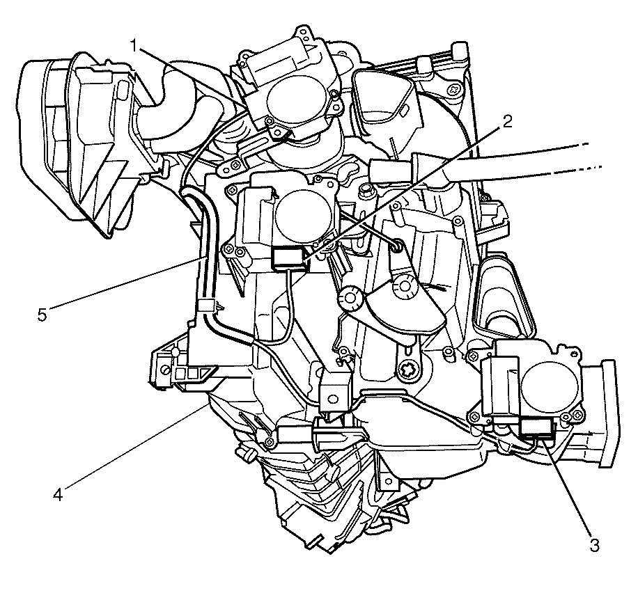
- Disconnect the main mode actuator electrical connector (1).
- Disconnect the air mix actuator electrical connector (2).
- Disconnect the rear mode actuator electrical connector (3).
- Detach the wiring harness (5) from the HVAC module assembly (4).
- Detach the wiring harness (1) from the HVAC module assembly (2).
- Remove the foam seal (1) from the HVAC module assembly (2).
- Remove the TX valve positioning bracket to the HVAC module assembly retaining screws (2).
- Remove TX valve positioning bracket (3) from the HVAC module assembly (1).
- Remove the upper retaining plastic cover (1) from HVAC module assembly (2).
- Remove the evaporator pipe assembly to evaporator retaining bolts (4).
- Remove the evaporator pipe assembly (5) from the evaporator (3).
- Remove the HVAC module assembly retaining clips (1) from the HVAC module assembly (2).
- Remove the left side HVAC module assembly housing to right side HVAC module assembly housing retaining screws (1).
- Separate the left side HVAC module assembly housing (1) from the right side HVAC module assembly housing (2).
- Remove the evaporator temperature sensor (3) from the evaporator (2).
- Remove the evaporator (2) from the HVAC module assembly (1).
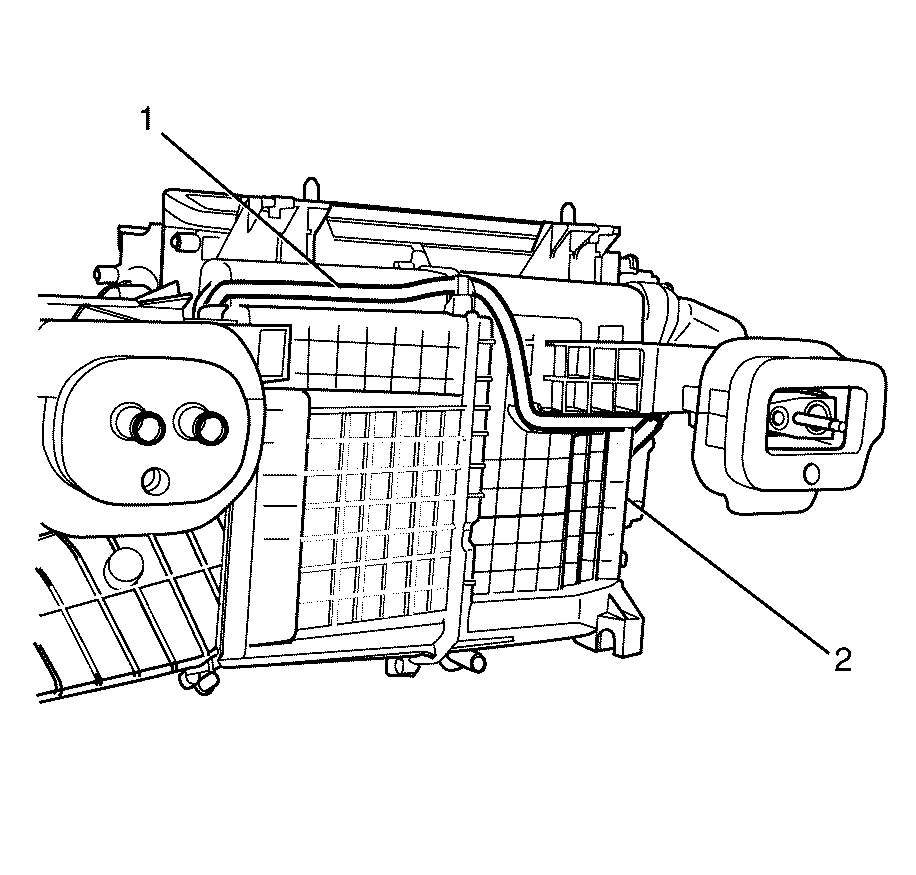
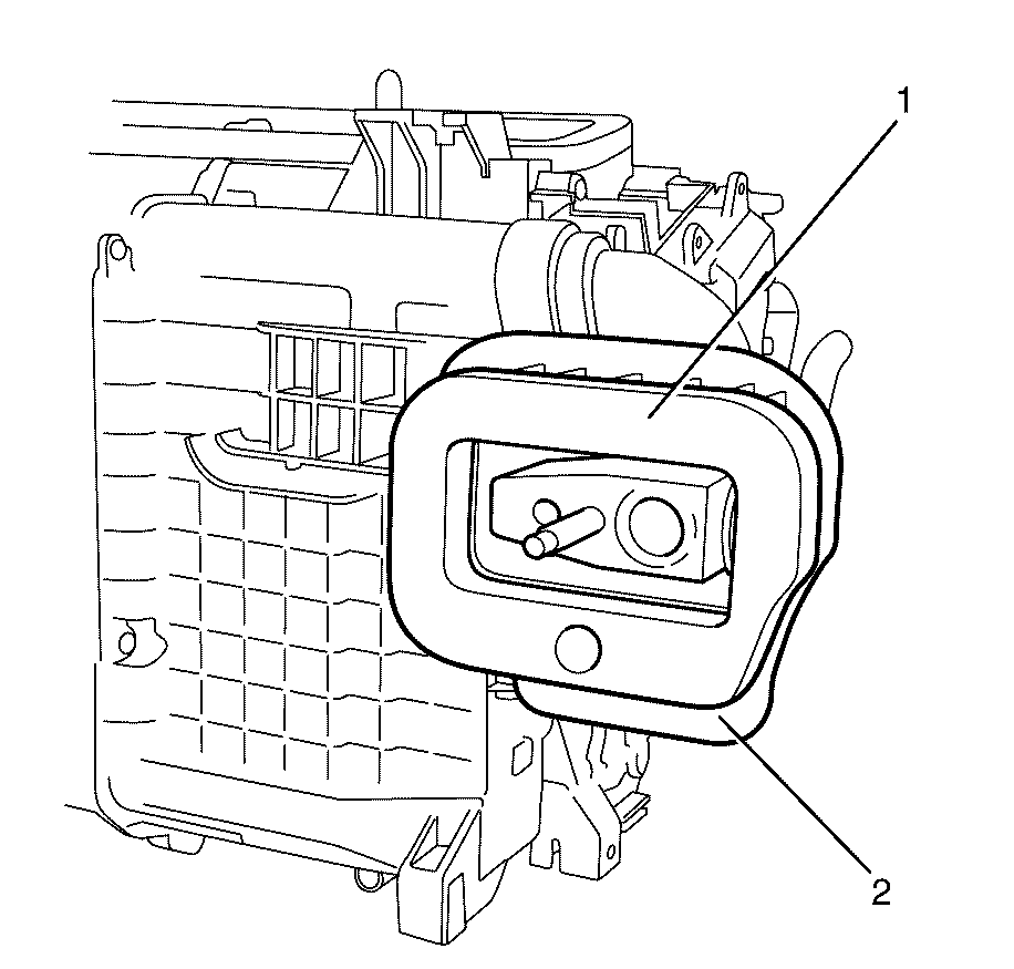
Important: Do not damage the foam seal (1).
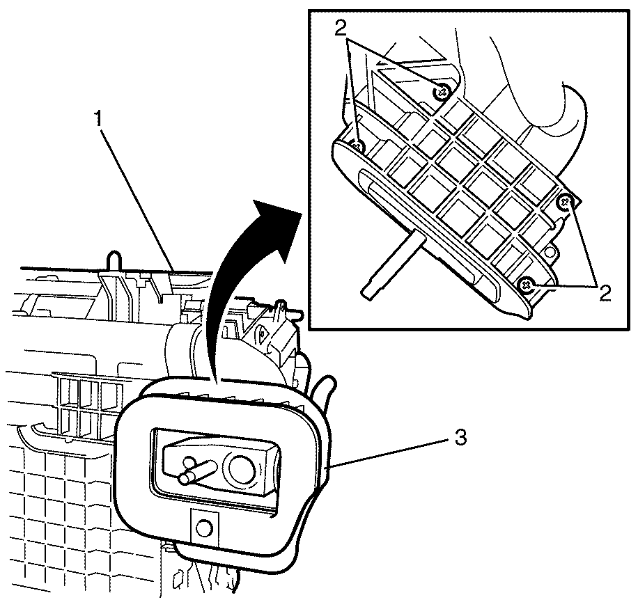
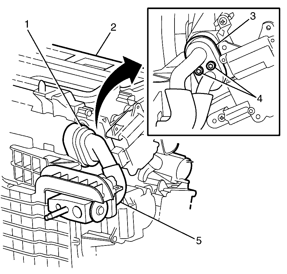
Important: Unclip the upper plastic retaining cover (1) to remove.
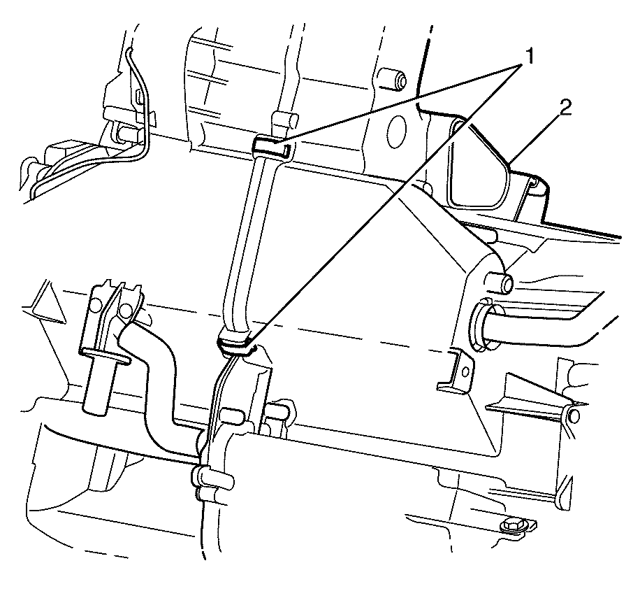
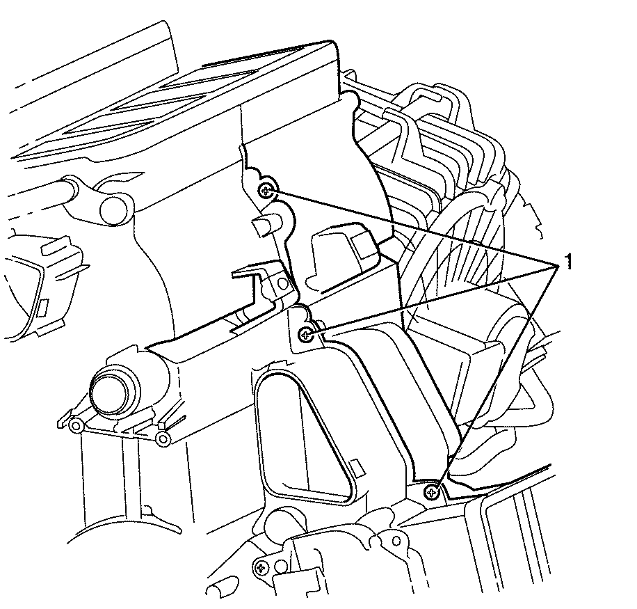
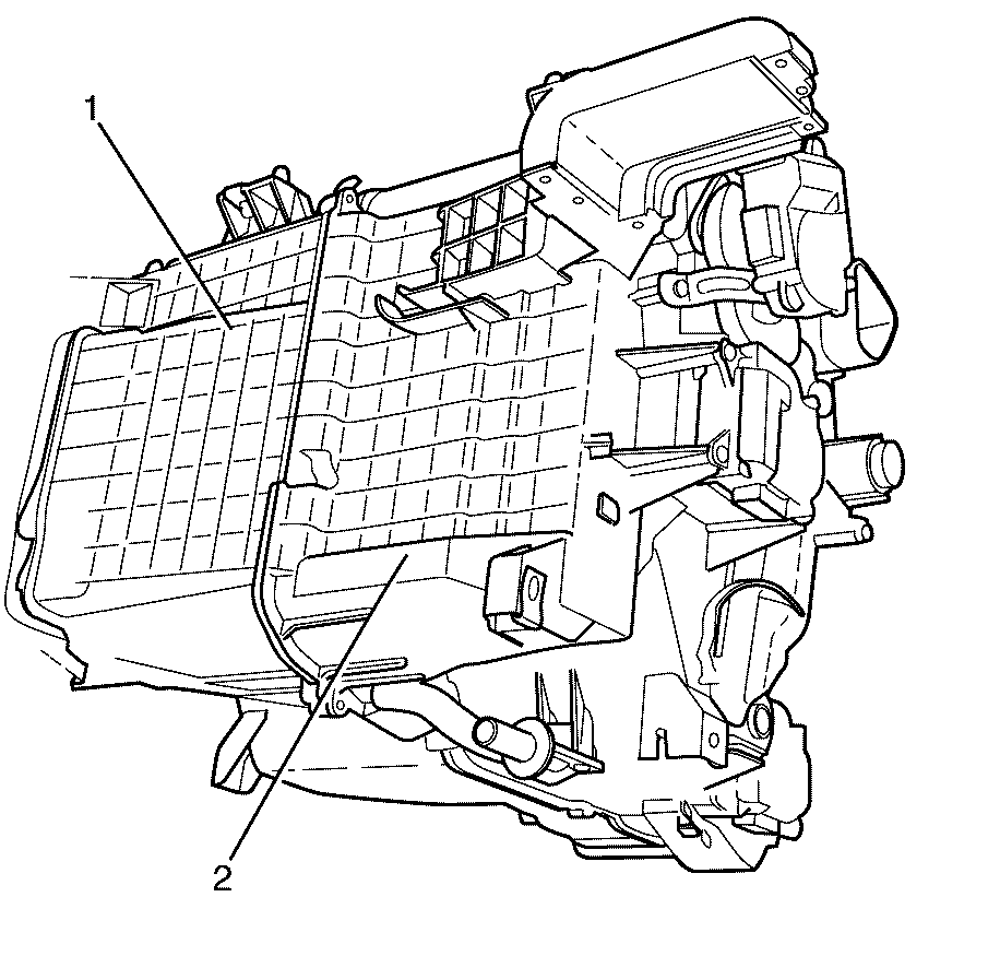
Important: Make sure the air distribution flaps and linkages are not damaged on removal, otherwise incorrect HVAC operation may result.
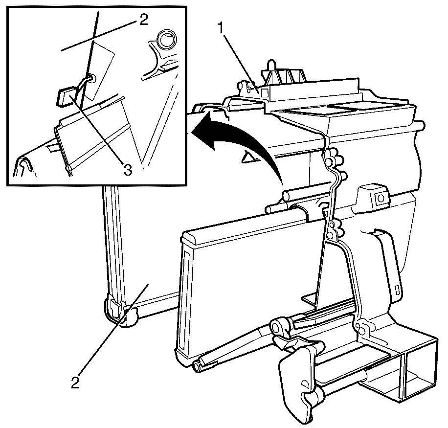
Important: Use a suitable tool to remove the evaporator temperature sensor (3) from the evaporator (2).
Important: Remove the evaporator (2) by sliding it out of the HVAC module assembly (1).
Installation Procedure
- Install the evaporator (2) to the HVAC module assembly (1).
- Install the evaporator temperature sensor (3) to the evaporator (2).
- Install the left side HVAC module assembly housing (1) to the right side HVAC module assembly housing (2).
- Install the left side HVAC module assembly housing to right side HVAC module assembly housing retaining screws (1).
- Install the HVAC module assembly retaining clips (1) to the HVAC module assembly (2).
- Install NEW O-rings (1) to the evaporator (2). Refer to O-Ring Replacement.
- Install the evaporator pipe assembly (5) to the evaporator (3).
- Install the evaporator pipe assembly to evaporator retaining bolts (4)
- Install the upper retaining plastic cover (1) to the HVAC module assembly (2).
- Install the TX valve positioning bracket (3) to the HVAC module assembly (1).
- Install the TX valve positioning bracket to HVAC module assembly retaining screws (2).
- Install the foam seal (1) to the HVAC module assembly (2).
- Install the wiring harness (1) to the HVAC module assembly (2).
- Install the wiring harness (5) to the HVAC module assembly (4).
- Connect the main mode actuator electrical connector (1).
- Connect the air mix actuator electrical connector (2).
- Connect the rear mode actuator electrical connector (3).
- Install the HVAC module assembly. Refer to HVAC Module Assembly Replacement.

Important: DO NOT force the evaporator (2) into the HVAC module assembly (1). Damage to the evaporator temperature sensor (3) can occur.
Important: Install the evaporator temperature sensor (3) to the evaporator (2) 22.2 mm (7/8 in) from the side of the evaporator and 50 mm (2 in) from the bottom of the evaporator.

Important: Make sure the air distribution flaps and linkages are not damaged on removal, otherwise incorrect HVAC operation may result.
Notice: Refer to Fastener Notice in the Preface section.

Tighten
Tighten the screws to 1 N·m (8 lb in).

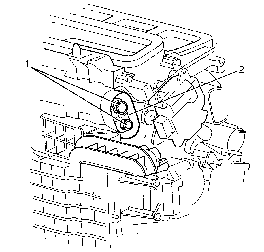

Tighten
Tighten the bolts to 3.5 N·m
(31 lb in).

Tighten
Tighten the screws to 1 N·m (9 lb in).

Important: Using a commercially available adhesive install the foam seal (1) to the HVAC module assembly (2)


