Tools Required
J 38185 Hose Clamp Pliers
Removal Procedure
- Recover the refrigerant. Refer to Refrigerant Recovery and Recharging .
- Disconnect the battery negative cable. Refer to Battery Negative Cable Disconnection and Connection .
- Remove the engine cover. Refer to Engine Cover Replacement or Engine Cover Replacement .
- Remove the windscreen wiper arms. Refer to Windshield Wiper Arm Replacement .
- Remove the air inlet grill panel. Refer to Air Inlet Grille Panel Replacement .
- Remove the air filter assembly. Refer to Air Cleaner Assembly Replacement or Air Cleaner Assembly Replacement .
- Drain the cooling system. Refer to Cooling System Draining and Filling .
- Using J 38185 compress the heater hose retaining clamps (1) and slide along the heater hose (3).
- Remove the heater hoses (3) from the heater core pipes (2).
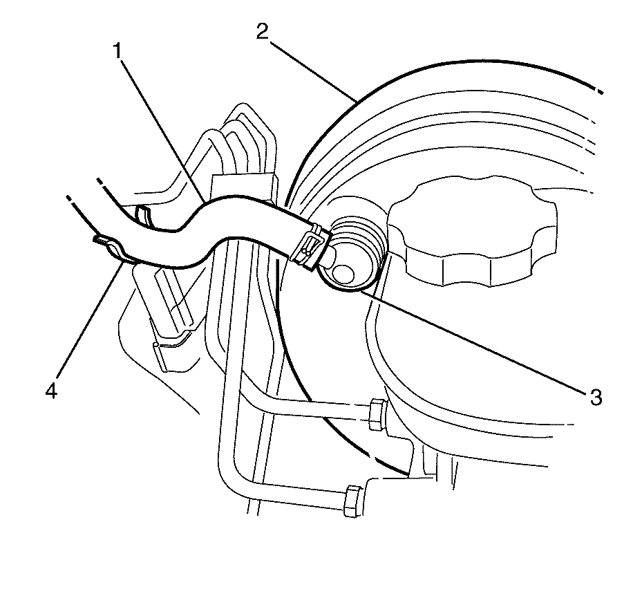
- Disconnect the vacuum hose (1) and the vacuum brake booster check valve (3) from the vacuum brake booster (2).
- Detach the vacuum hose (1) from the bulkhead mounted vacuum hose retaining bracket (4) and position aside.
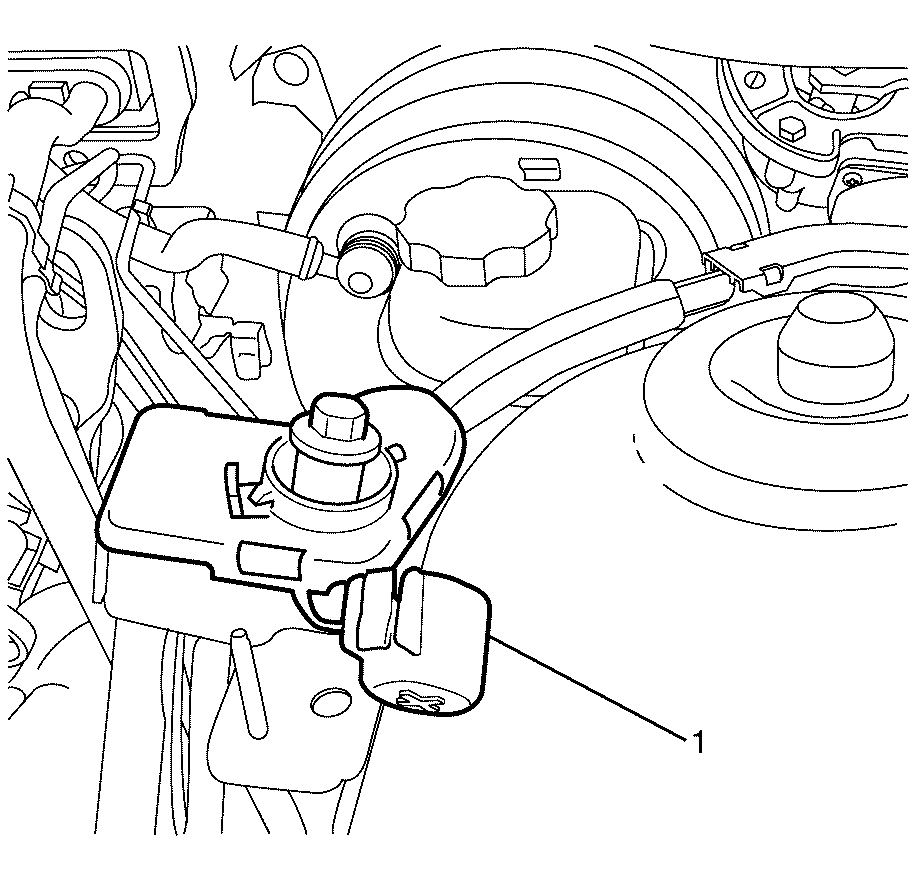
- Remove the remote battery positive post cover (1).
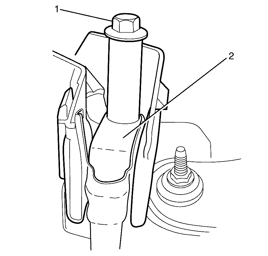
- Remove the remote battery positive post to wiring harness retaining bolt (1).
- Remove the starter motor power cable (2) and position aside.
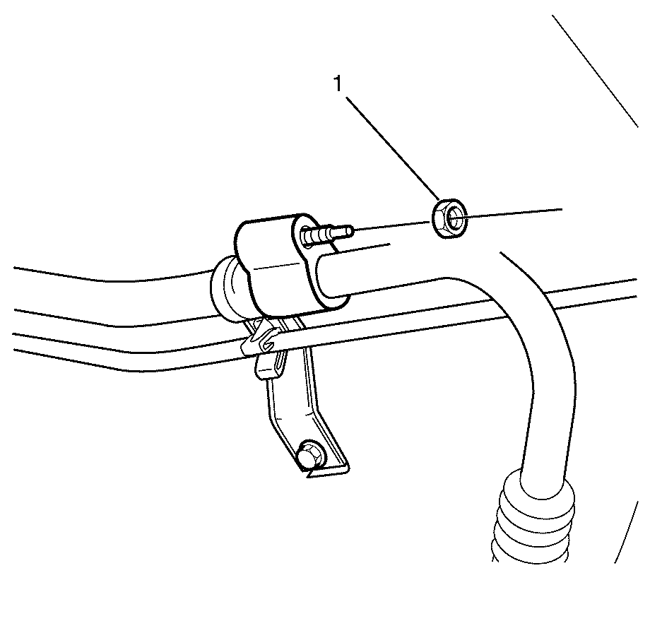
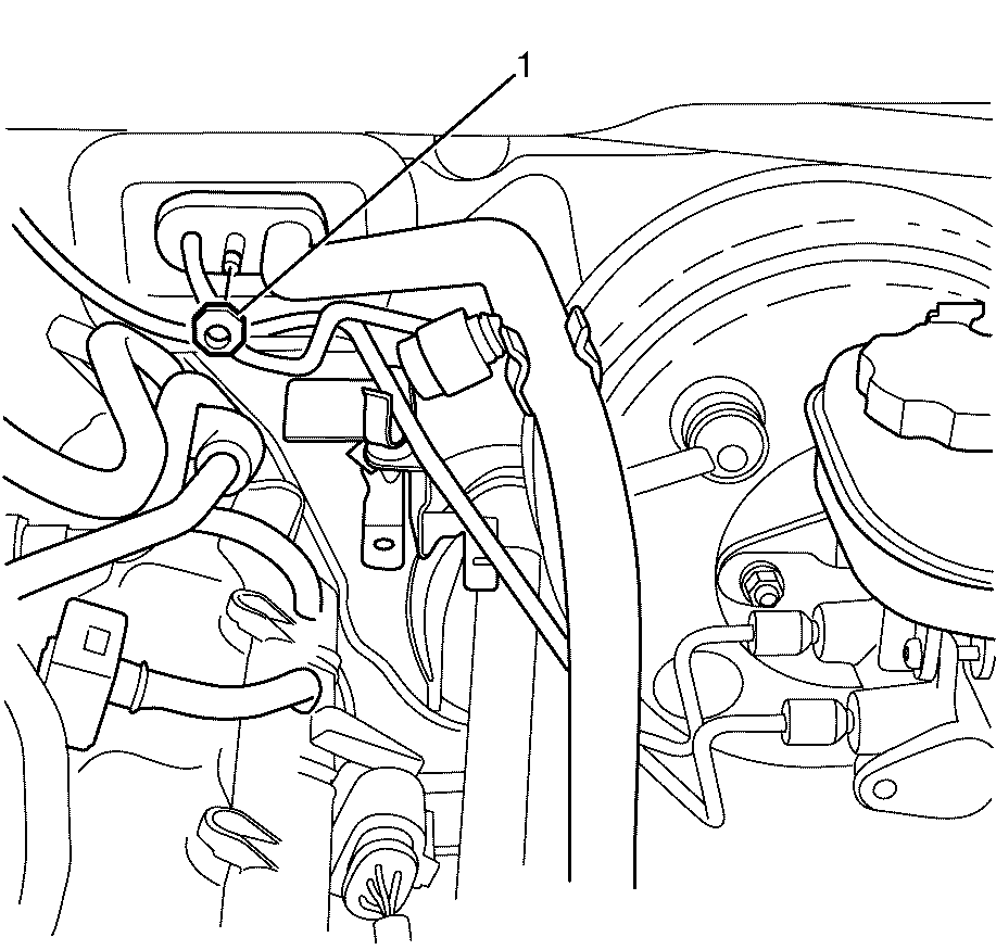
- Remove the suction pipe upper to suction pipe lower retaining nut (1).
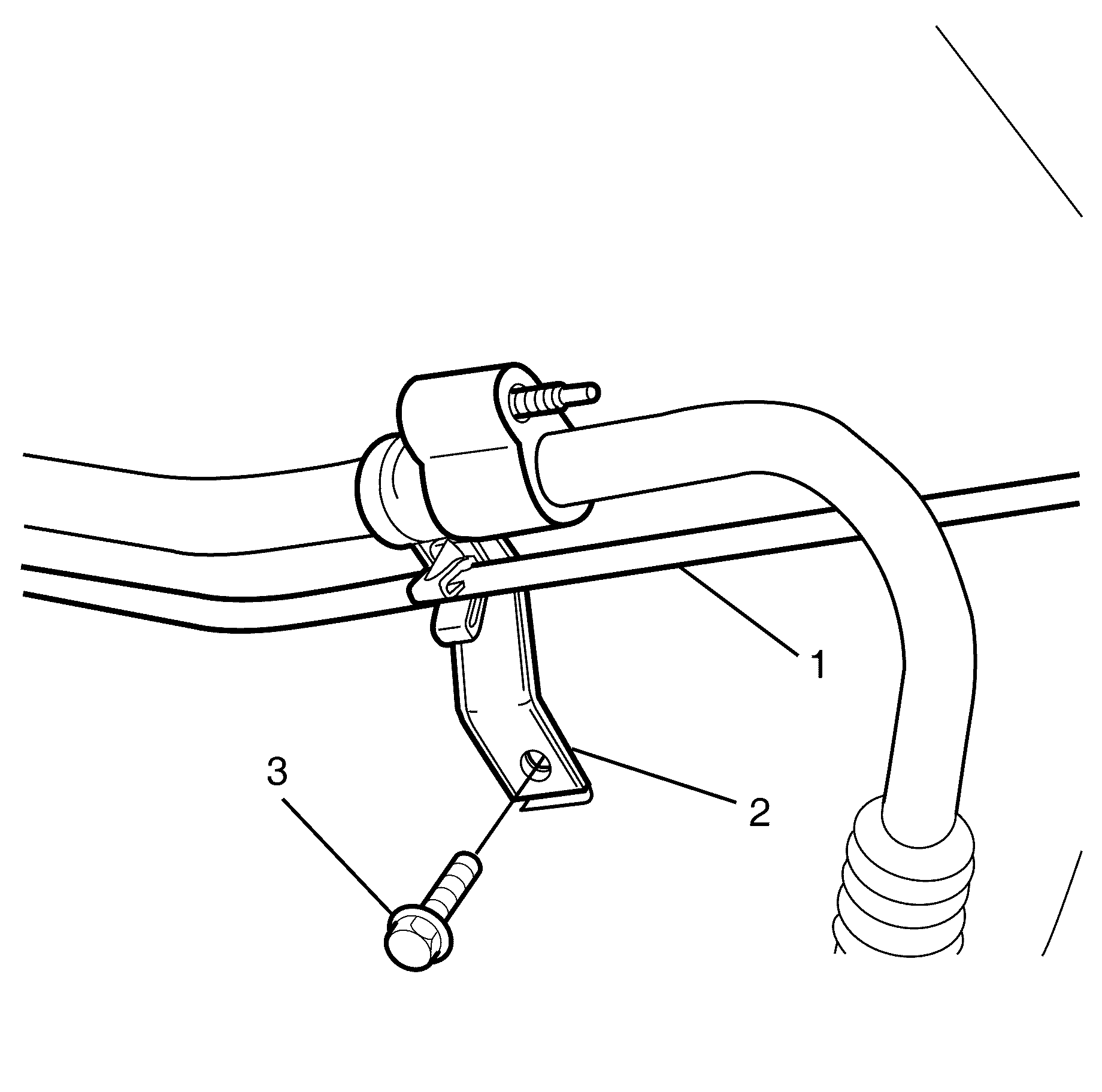
- Remove the suction pipe/liquid pipe retaining clip to left front chassis rail retaining bolt (3).
- Detach the liquid pipe (1) from the suction pipe/liquid pipe retaining clip (2).
- Disconnect the suction pipe upper (1) from suction pipe lower (2).
- Remove the sealing washer (3). Refer to Sealing Washer Replacement .
- Cap or plug the suction pipe upper (1) and the suction pipe lower (2).
- Remove the suction pipe/liquid pipe pad to TX valve retaining nut (1).
- Disconnect the suction pipe/liquid pipe pad (3) from the TX valve (1).
- Remove the sealing washers (2). Refer to Sealing Washer Replacement .
- Cap or plug the suction pipe (4), liquid pipe (5) and the TX valve (1).
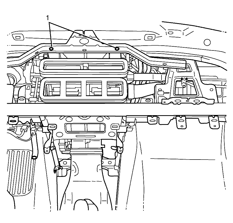
- Remove the HVAC to bulkhead retaining bolts (1).
- Disconnect the blower motor electrical connector (2).
- Disconnect the HVAC module electrical connectors (3).
- Disconnect the blower motor control processor electrical connector (1).
- Detach the I/P wiring harness to HVAC module assembly retaining clips (4).
- Remove the instrument panel (I/P) pad. Refer to Instrument Panel Upper Trim Pad Replacement .
- Remove the instrument panel centre support bracket. Refer to Instrument Panel Retainer Replacement .
- Remove the HVAC module assembly to I/P carrier retaining bolts (1).
- Remove the HVAC module assembly to I/P carrier retaining bolts (1).
- Remove the I/P carrier. Refer to Instrument Panel Carrier Replacement .
- Remove the HVAC module assembly (2) from the vehicle body (1).
Caution: Refer to Safety Glasses Caution in the Preface section.
Caution: Refer to Battery Disconnect Caution in the Preface section.
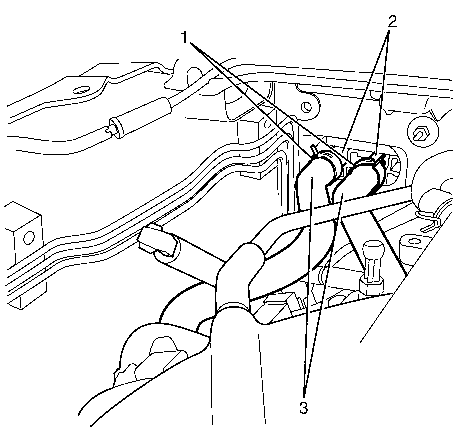
Important: Heater hoses for 3.6 litre engine are shown. 6.0 litre engine heater hoses are similar.
Important: Mark position of heater hoses (3) and heater hose retaining clamps (1) before removal to make sure of correct alignment during assembly.
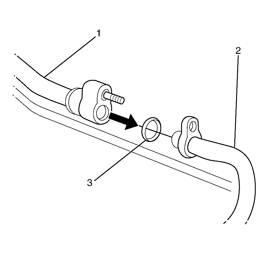
Important: The sealing washer (3) is a single use item and must be discarded after use.
Discard the sealing washer
Important: Cover any opening of the A/C system with a suitable cap or tape immediately, to prevent absorption of moisture from the atmosphere.
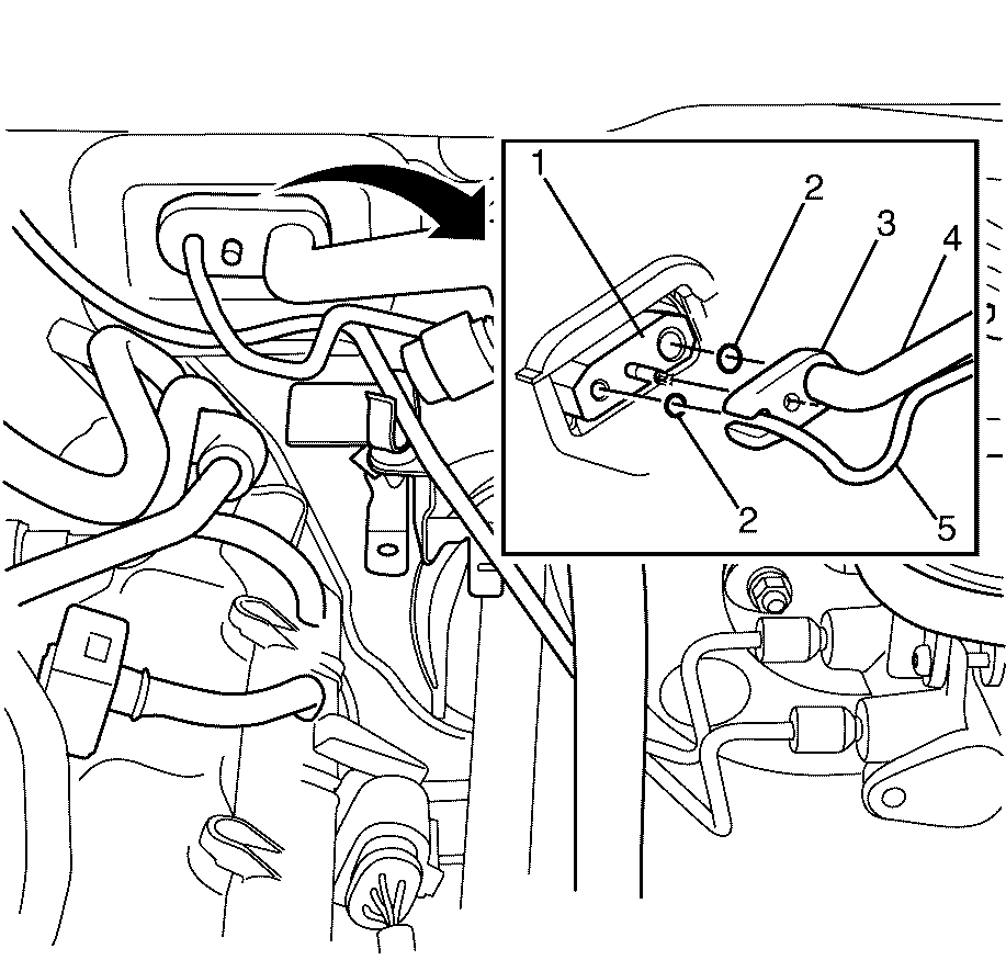
Important: The sealing washers (2) are a single use item and must be discarded after use.
Discard the sealing washers
Important: Cover any opening of the A/C system with a suitable cap or tape immediately, to prevent absorption of moisture from the atmosphere.
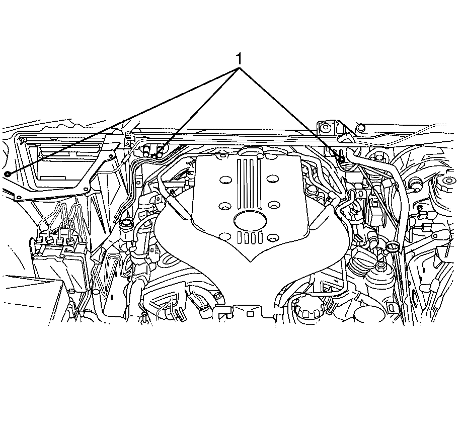
Important: HVAC to bulkhead retaining bolt locations are shown in a 3.6 litre engine compartment. 6.0 litre engine compartment HVAC to bulkhead retaining bolt locations are the same.
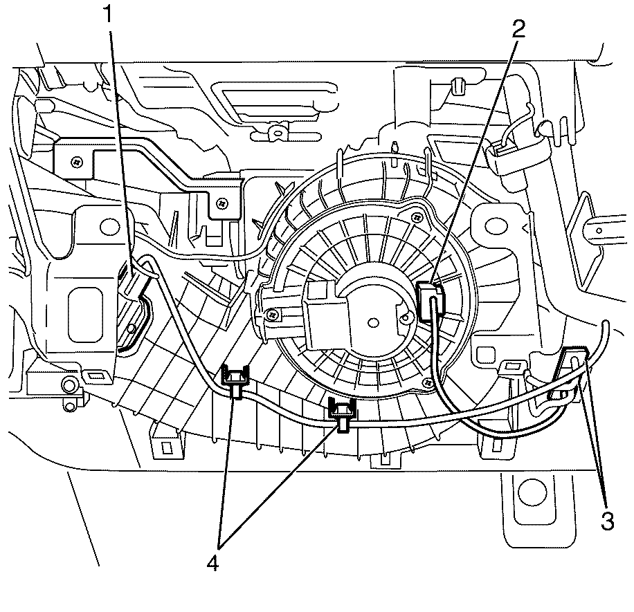
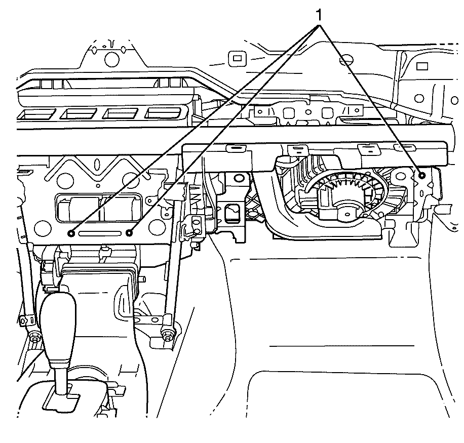
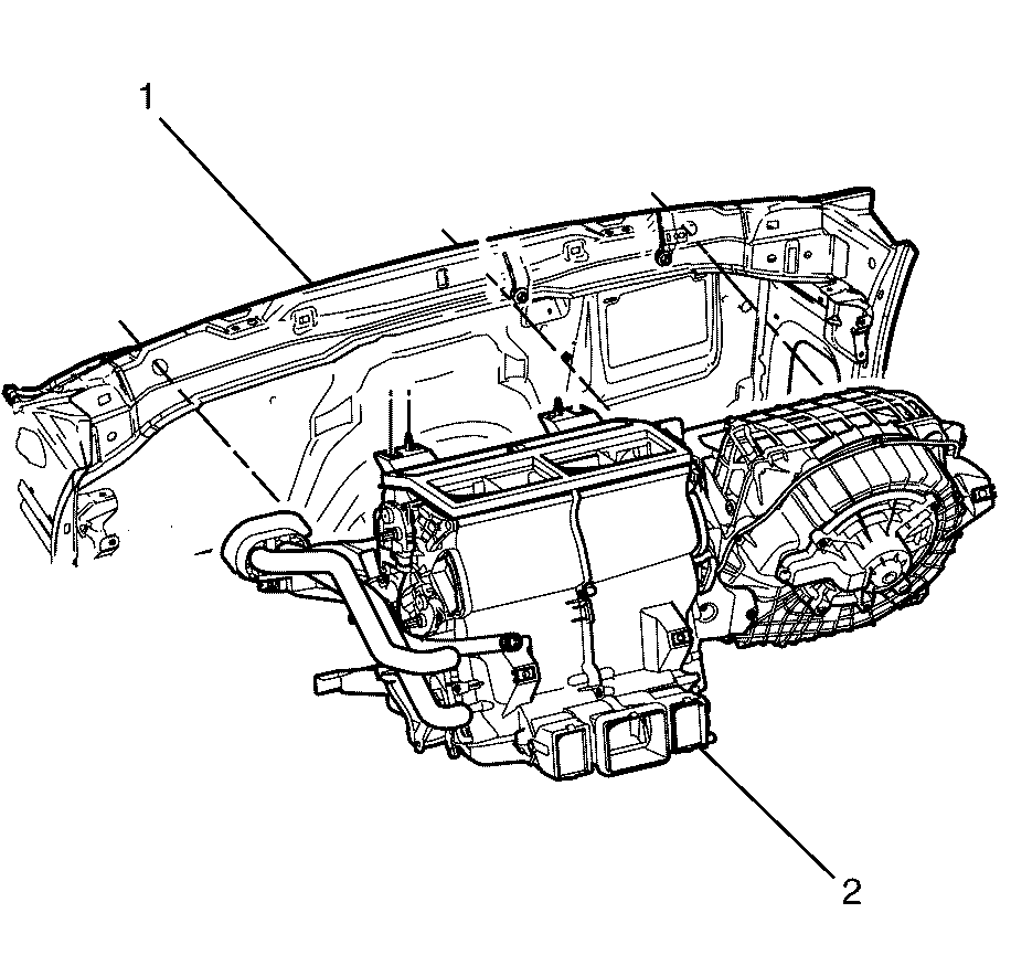
Important: To remove the HVAC module assembly (2) from the vehicle (1) rotate the HVAC module assembly (2) downwards and towards the back of the vehicle (1).
Installation Procedure
- Install the HVAC module assembly (1) to the vehicle body (2).
- Install the I/P carrier. Refer to Instrument Panel Carrier Replacement .
- Install the HVAC module assembly to I/P carrier retaining bolts (1).
- Install the HVAC module assembly to I/P carrier retaining bolts (1).
- Install the HVAC module assembly to bulkhead retaining bolts (1).
- Connect the blower motor control processor electrical connector (1).
- Connect the HVAC module electrical connectors (3).
- Connect the blower motor electrical connector (2).
- Attach the I/P wiring harness to HVAC module assembly retaining clips (4).
- Install the I/P upper trim pad. Refer to Instrument Panel Upper Trim Pad Replacement .
- Install the I/P retainer bracket. Refer to Instrument Panel Retainer Replacement .
- Remove the plugs or caps from the suction pipe (4), liquid pipe (5) and the TX valve (1).
- Install NEW sealing washers (2). Refer to Sealing Washer Replacement .
- Position the suction pipe/liquid pipe pad (3) to the TX Valve (1).
- Install the suction pipe/liquid pipe pad to TX valve retaining nut (1).
- Remove the plugs or caps from the suction pipe upper (1) and the suction pipe lower (2).
- Install a NEW sealing washer (3). Refer to Sealing Washer Replacement .
- Install the suction pipe upper (1) to the suction pipe lower (2).
- Attach the liquid pipe (1) to the suction pipe/liquid pipe retaining clip (2).
- Install the suction pipe/liquid pipe retaining clip to left front chassis rail retaining bolt (3).
- Install the suction pipe upper to suction pipe lower retaining nut (1).
- Install the starter motor positive cable (2) to the remote battery positive post (3).
- Install the remote battery positive post to wiring harness retaining bolt (1).
- Install the remote battery positive post cover (1).
- Connect the vacuum hose (1) and the vacuum brake booster check valve (3) to the vacuum brake booster (2).
- Attach the vacuum hose (1) to the bulkhead mounted vacuum hose retaining bracket (4).
- Connect the heater hoses (3) to the heater core pipes (2).
- Using J 38185 J 38185, slide the heater hose retaining clamps (1) back into the original position on the heater hoses (3).
- Install the engine cover. Refer to Engine Cover Replacement or Engine Cover Replacement .
- Install windscreen wiper arms. Refer to Windshield Wiper Arm Replacement .
- Install the air inlet grill panel. Refer to Air Inlet Grille Panel Replacement .
- Install the air filter assembly. Refer to Air Cleaner Assembly Replacement or Air Cleaner Assembly Replacement .
- Connect the battery negative cable. Refer to Battery Negative Cable Disconnection and Connection .
- Fill the cooling system. Refer to Cooling System Draining and Filling .
- Evacuate and recharge the A/C system. Refer to Refrigerant Recovery and Recharging .
- Leak test the HVAC module assembly pipe connections. Refer to Leak Testing .

Important: To install the HVAC module assembly (2) to the vehicle (1) rotate the HVAC module assembly (2) upwards and towards the front of the vehicle (1).
Important: Make sure the HVAC module assembly (3) fits into the drain assembly
Notice: Refer to Fastener Notice in the Preface section.

Tighten
Tighten the bolts to 9 N·m (80 lb in).

Tighten
Tighten the bolts to 9 N·m(80 lb in).

Important: HVAC to bulkhead retaining bolt locations are shown in a 3.6 litre engine compartment. 6.0 litre engine compartment HVAC to bulkhead retaining bolt locations are the same.
Tighten
Tighten the bolts to 7 N·m (62 lb in).


Important: DO NOT coat the NEW sealing washers (2) with oil, they must be fitted dry. The use of mineral oil will render the sealing washers (2) useless, as the sealing washers (2) WILL swell causing refrigerant to leak out.
Notice: Refer to Fastener Notice in the Preface section.

Tighten
Tighten the nut to 22 N·m(16 lb ft).
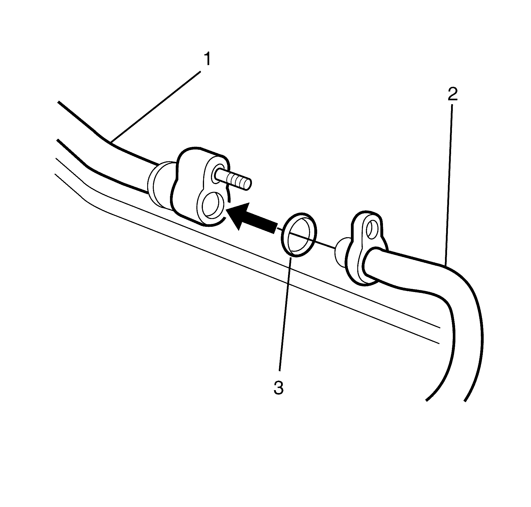
Important: DO NOT coat the NEW sealing washer (3) with oil, they must be fitted dry. The use of mineral oil will render the sealing washer (3) useless, as the sealing washer (3) WILL swell causing refrigerant to leak out.

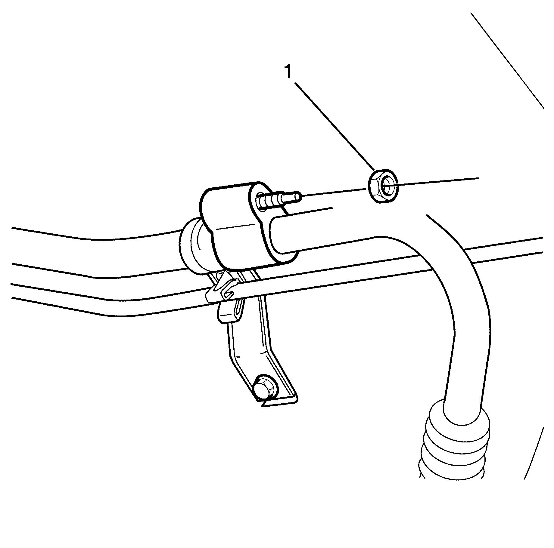
Tighten
Tighten the nut to 22 N·m( 16 lb ft).
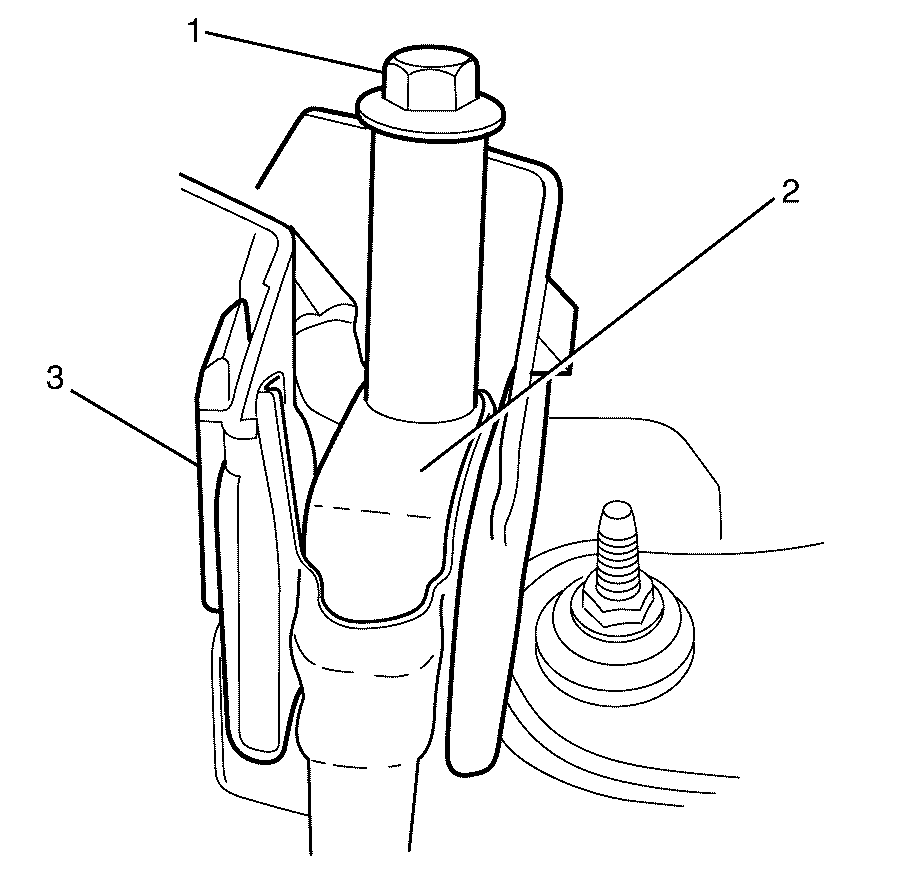
Tighten
Tighten the bolt to 15 N·m (11 lb ft).

Important: Make sure the clips on the remote battery positive post cover (1) are engaged to avoid an induced rattle condition.


Important: Heater hoses for 3.6 litre engine are shown. 6.0 litre engine heater hoses are similar.
Important: If reusing the heater hoses (3), align the heater hoses (3) with the marks made on the heater core inlet pipe (2) during the removal procedure.
