Special Tools
| • | J 21426 Installer |
| • | J-22912-01 Press Plates |
| • | J 22610 Keystone Pliers |
| • | J 5590 Bearing and Seal Driver |
Removal Procedure
- Raise and support the vehicle. Refer to Lifting and Jacking the Vehicle.
- Remove the propeller shaft from the vehicle. Refer to Propeller Shaft Replacement.
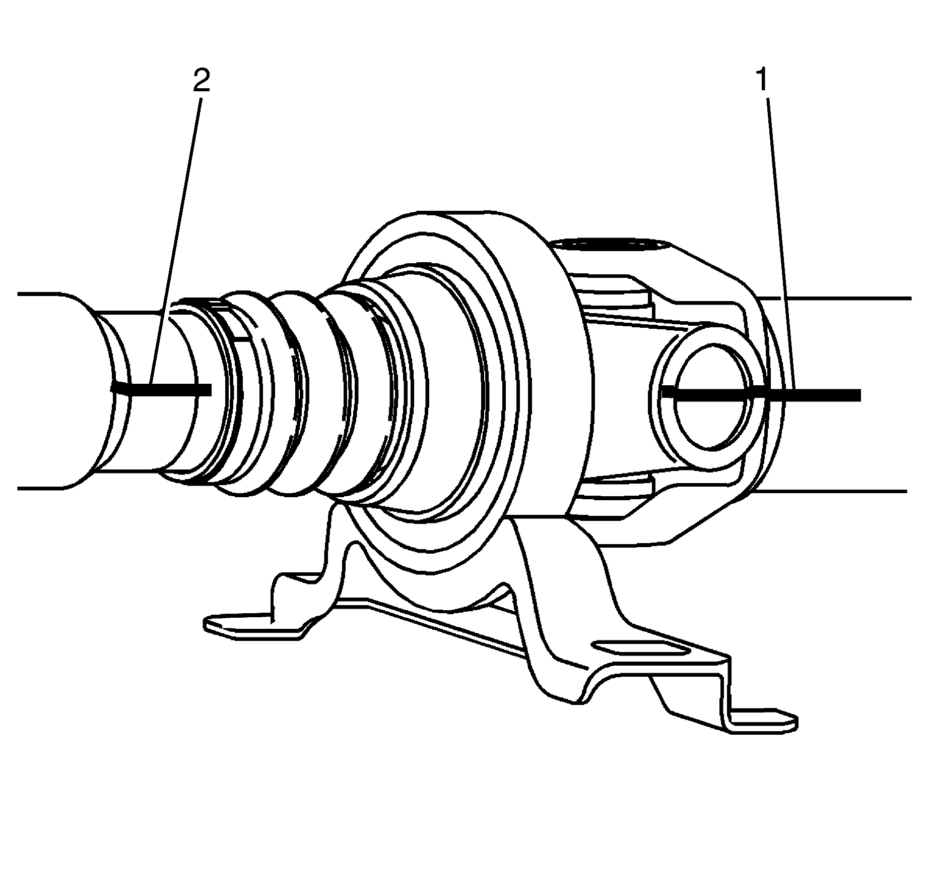
- Mark the position of the propeller shaft rear section (1) in relation to the propeller shaft front section (2).
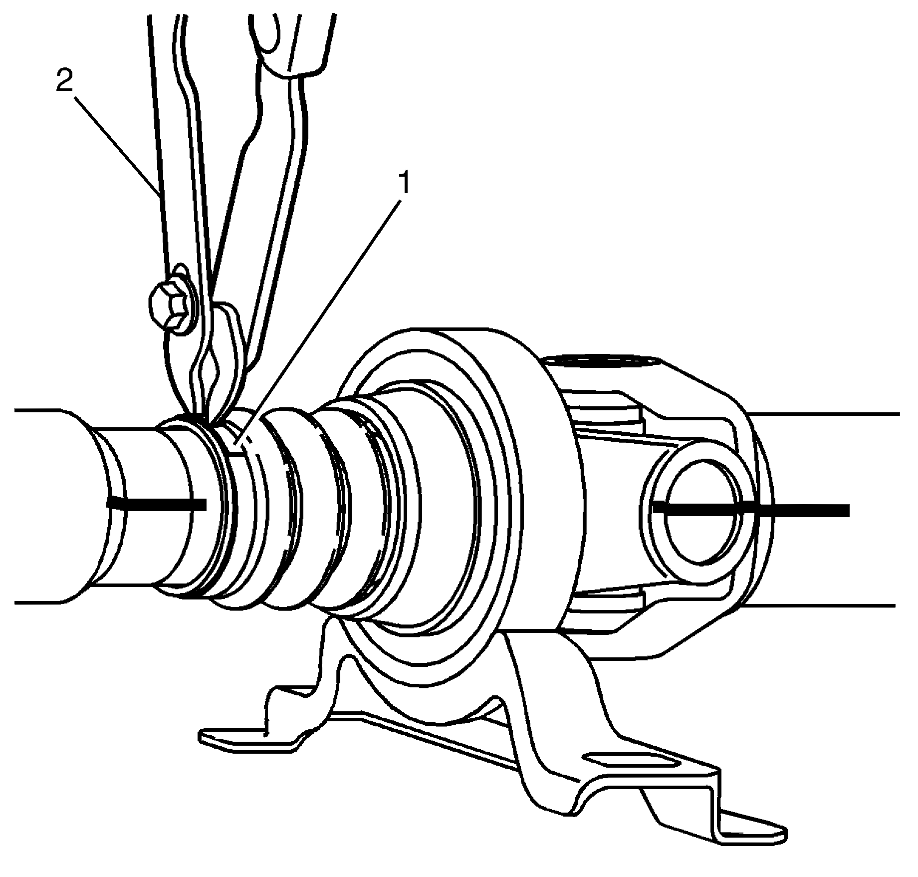
- Remove the dust boot to propeller shaft front section clamp (2).
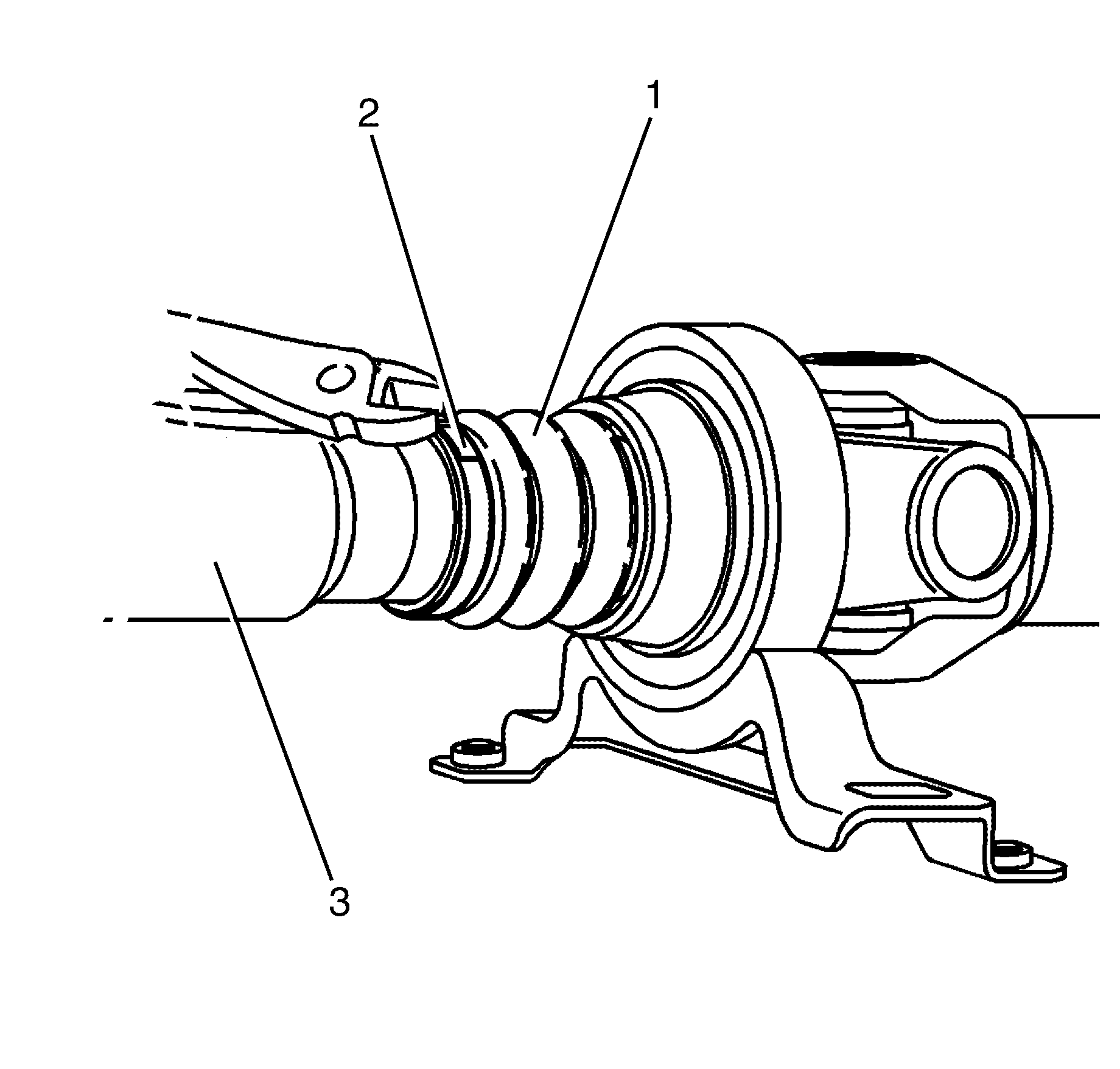
- Detach the dust boot (1) from the propeller shaft (3).
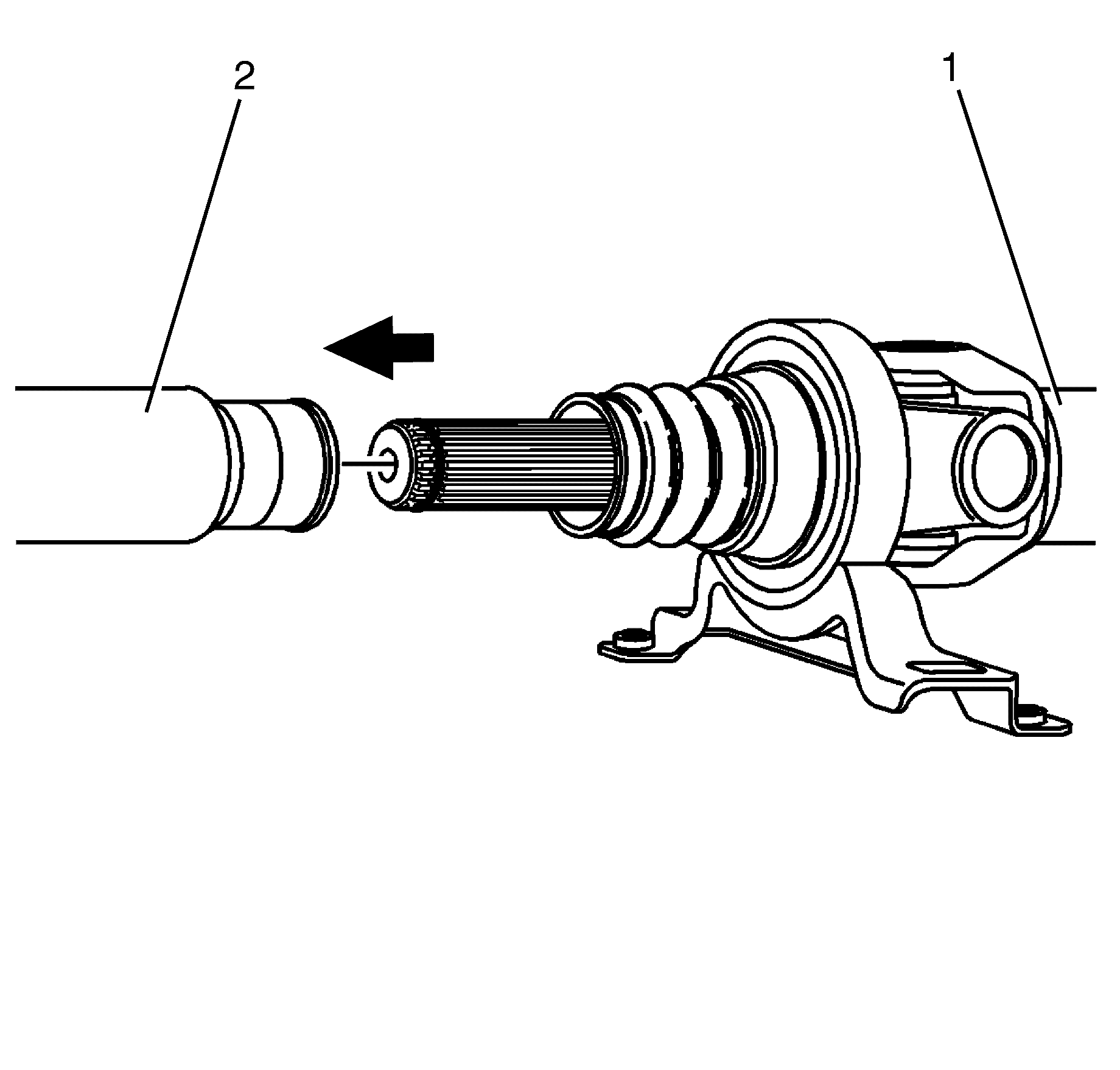
- Separate the propeller shaft rear section (1) from the propeller shaft front section (2).
- Remove the spline retention O-ring (2) from the propeller shaft (1).
- Remove the dust boot (3) from the propeller shaft (1).
- Remove the center bearing slinger (4) from the propeller shaft (1).
- Remove the propeller shaft (2) to center bearing (1) retaining circlip (3).
- Remove the center bearing (3) from the propeller shaft (2).
Warning: Refer to Safety Glasses Warning in the Preface section.
Danger: To avoid any vehicle damage, serious personal injury or death when major components are removed from the vehicle and the vehicle is supported by a hoist, support the vehicle with jack stands at the opposite end from which the components are being removed and strap the vehicle to the hoist.
Note: Never clamp the propeller shaft tubing in a vise. Clamping the propeller shaft tubing in a vise could dent or deform the tube causing an imbalance or unsafe condition. Always clamp on one of the propeller shaft yokes and support the propeller shaft horizontally.
Note: Correct alignment during assembly is critical in order to maintain correct balance.
Note: The propeller shaft splines are not keyed, therefore, alignment marks are necessary for assembly.
Note: The dust boot clamp is a single use part and must be discarded after use.
Discard the dust boot clamp.
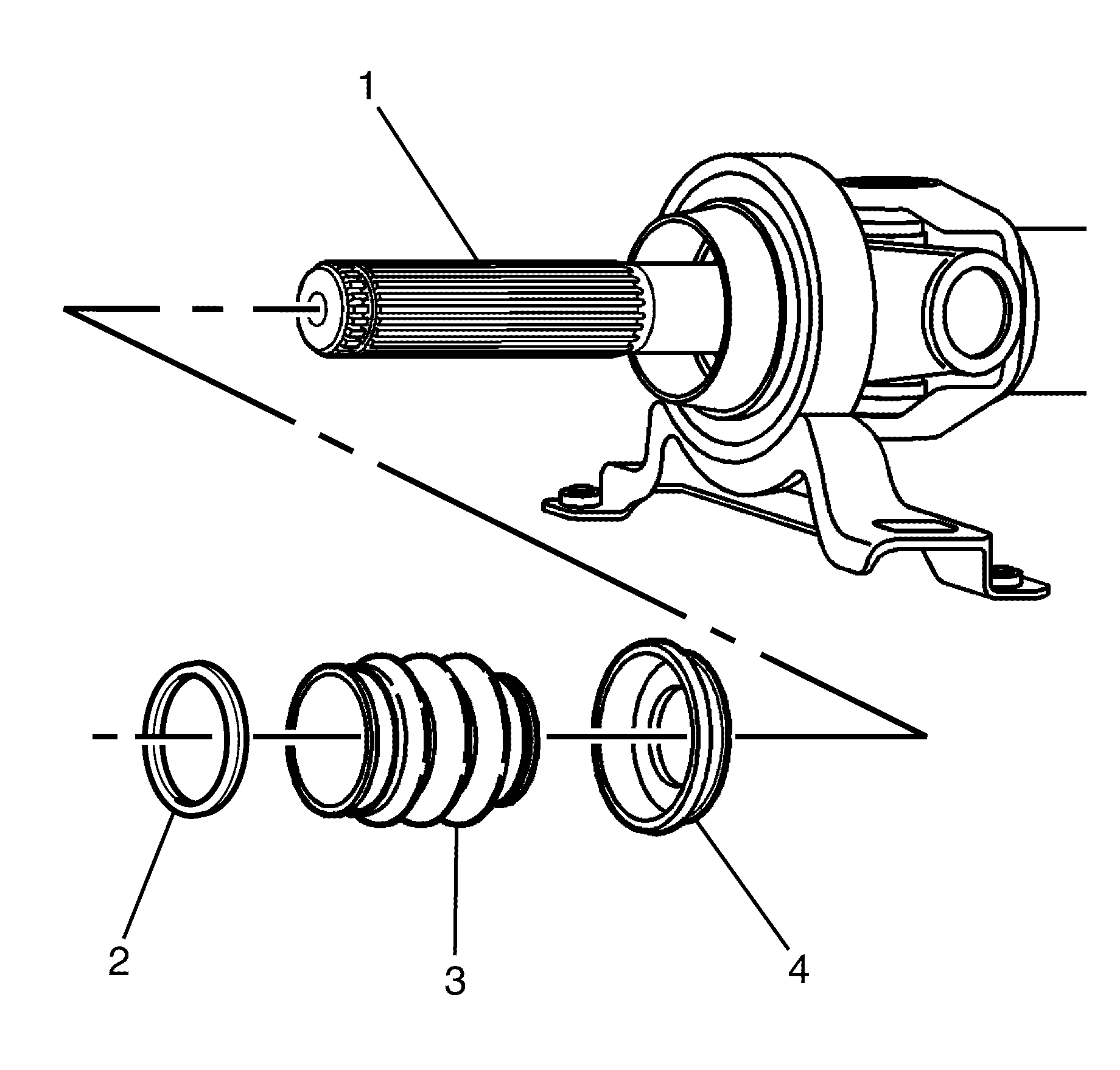
Note: The spline retention O-ring (2) is a single use part and must be discarded after use.
Discard the spline retention O-ring.
Note: The dust boot (3) is a single use part and must be discarded after use.
Discard the dust boot.
Note: The center bearing slinger (4) is a single use part and must be discarded after use.
Discard the center bearing slinger.
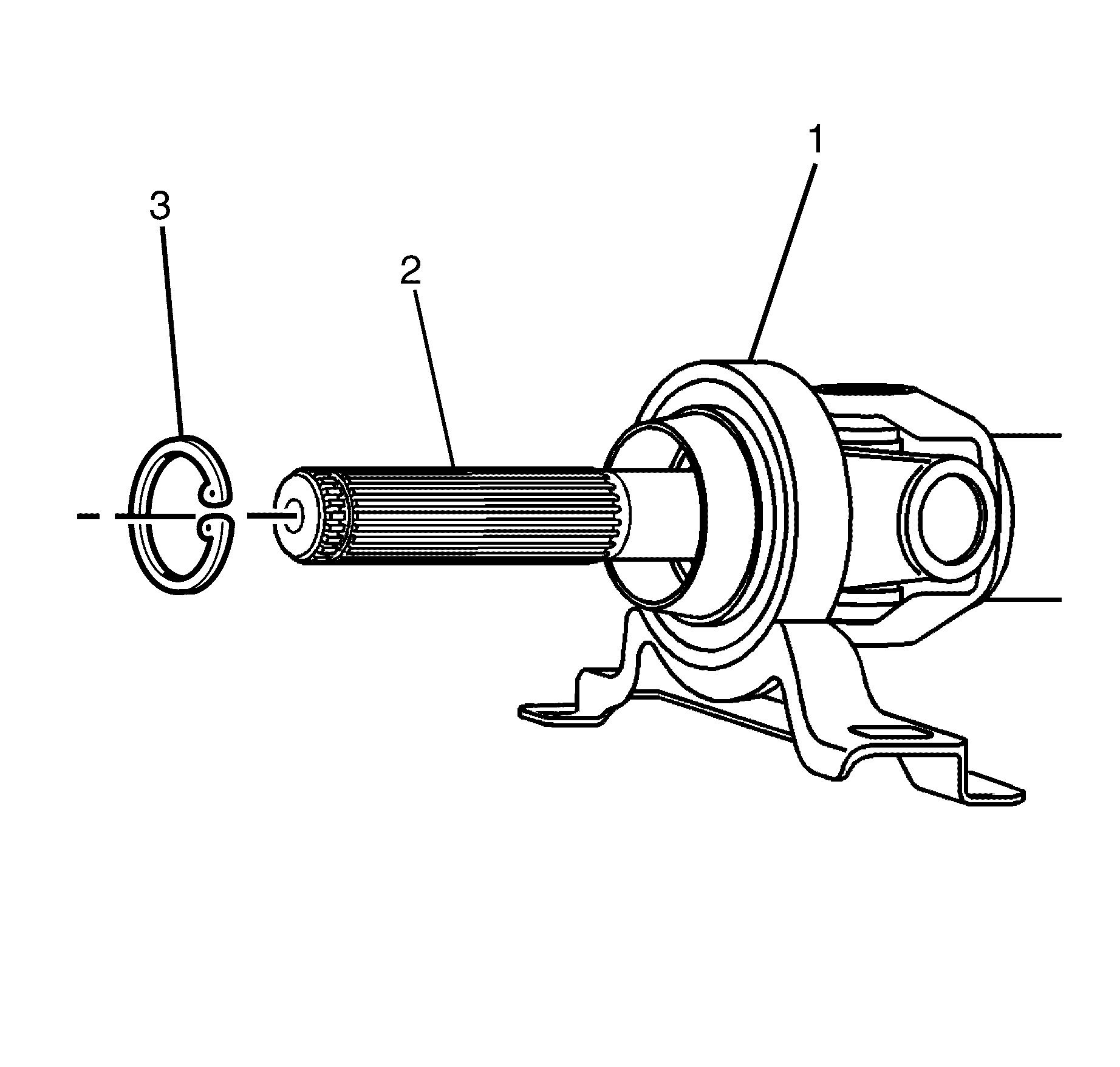
Note: The circlip (3) is a single use part and must be discarded after use.
Discard the circlip.
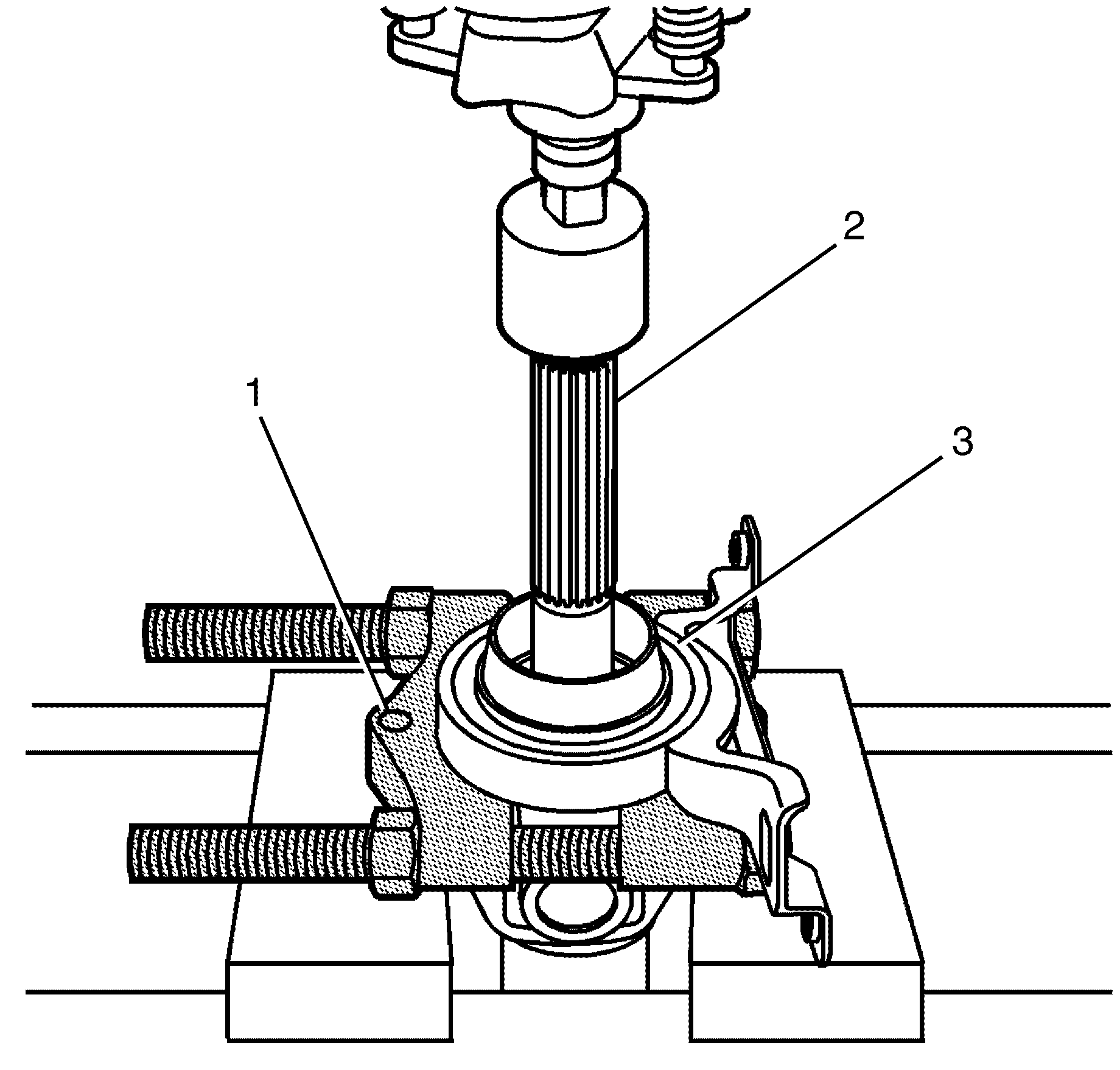
Note: Observe the orientation and depth of the center bearing (3) in relation to the propeller shaft (2).
Note: Install the J-22912-01 (1) to the rear propeller shaft (2) behind the center bearing (3). Place the rear propeller shaft (2) in a suitable press and remove the center bearing (3).
Clean and Inspect
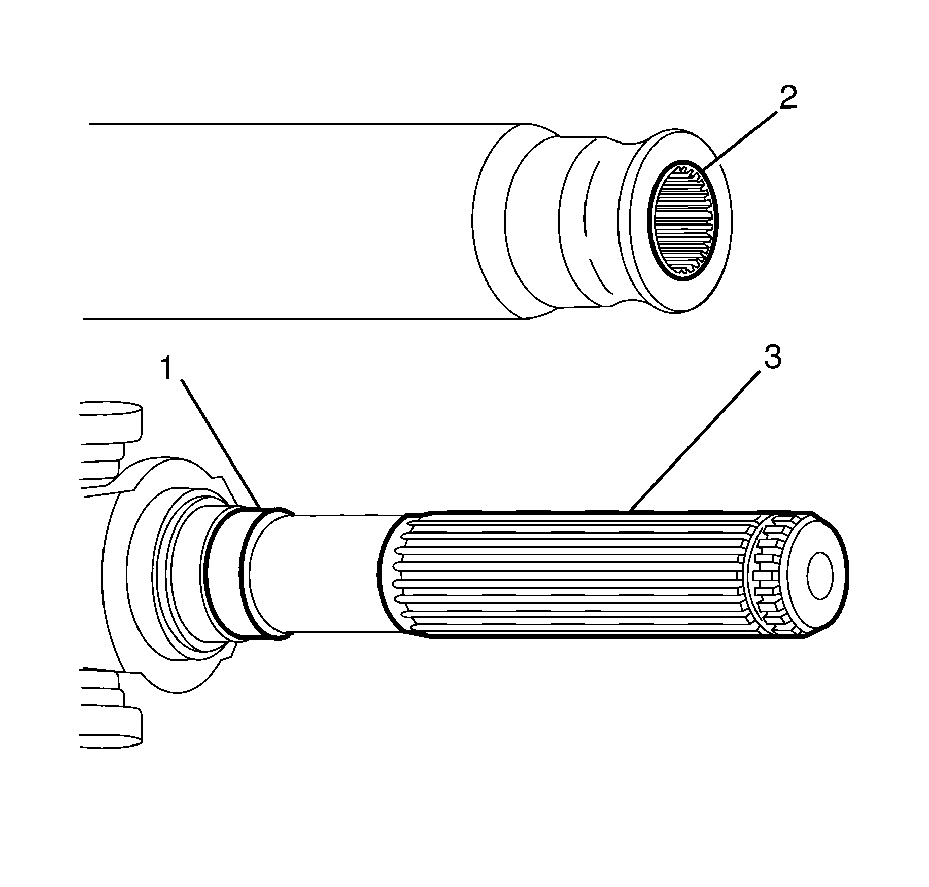
- Clean the grease from the front propeller shaft spline (2) and rear propeller shaft spline (3).
- Check the front propeller shaft spline (2) and rear propeller shaft spline (3) for damage and/or wear.
- Remove any corrosion or debris from the bearing area (1).
Installation Procedure
- Install the center bearing (1) to the propeller shaft (2).
- Install the propeller shaft (2) to center bearing (1) NEW retaining circlip (3).
- Install the NEW center bearing slinger (2).
- Lubricate the propeller shaft splines (1).
- Install the NEW dust boot (2) and NEW dust boot clamp (3) to propeller shaft rear section (1). Do not fully tighten the dust boot clamp.
- Install the NEW spline sealing O-ring (4) to the propeller shaft (1).
- Connect the propeller shaft rear section (1) to the propeller shaft front section (2).
- Attach the NEW dust boot (3) to the propeller shaft front section (2).
- Tighten the NEW dust boot clamp (1) using J 22610 keystone pliers (2).
- Install the propeller shaft to the vehicle. Refer to Propeller Shaft Replacement.
- Remove the safety stands.
- Lower the vehicle to the ground.
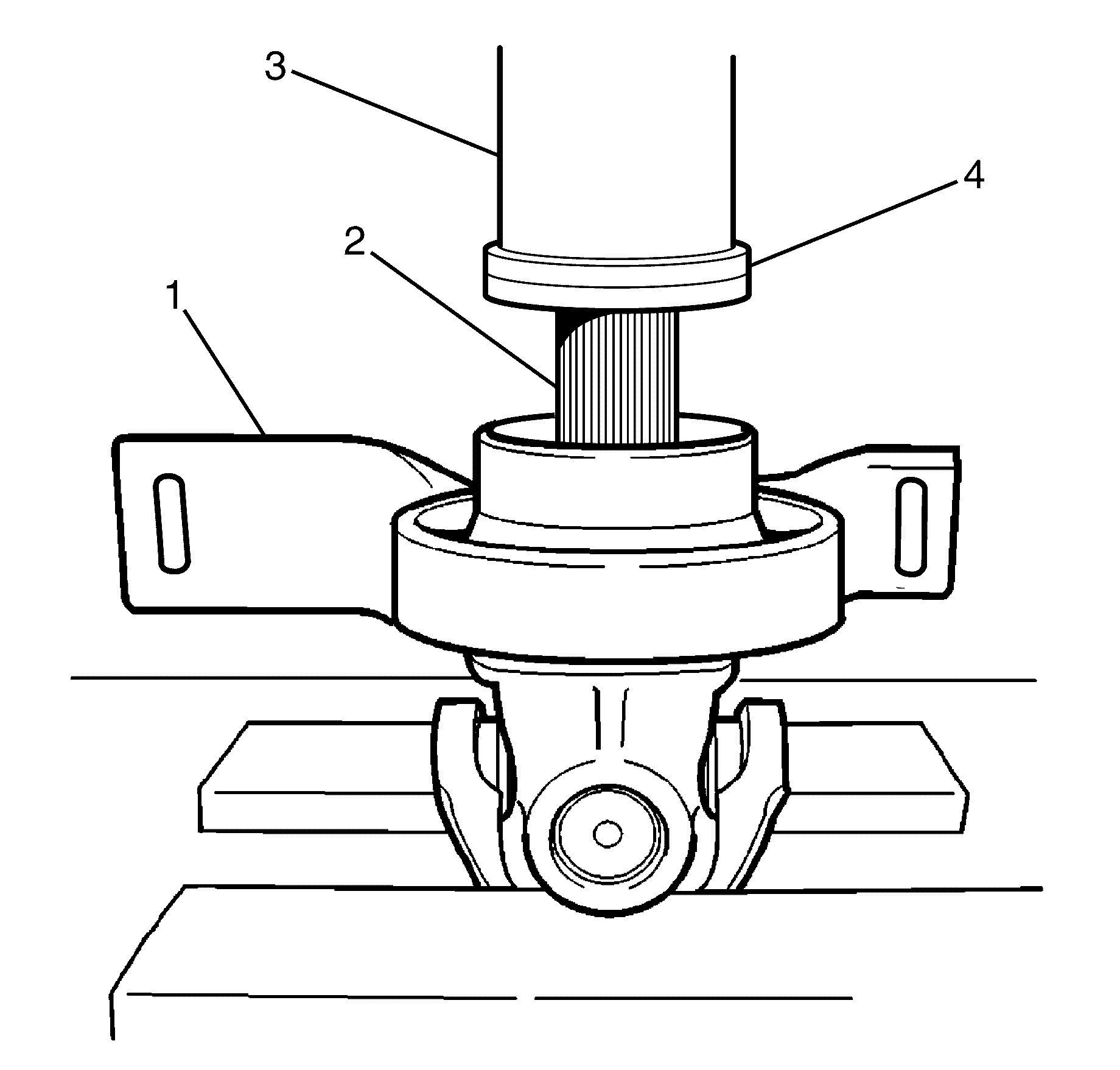
Note: Use a suitable press to install the center bearing (1) with J 5590 Bearing and Seal Driver (3) and adaptor (4) until it seats and the circlip groove is visible.

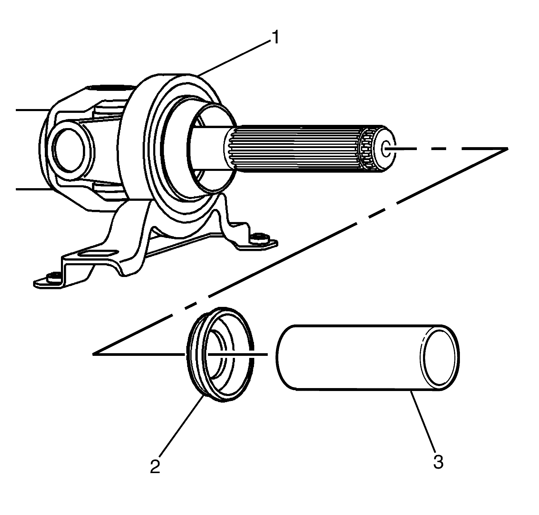
Note: Install the center bearing slinger (1) with J 21426 (3) until it seats fully onto the center bearing (1).
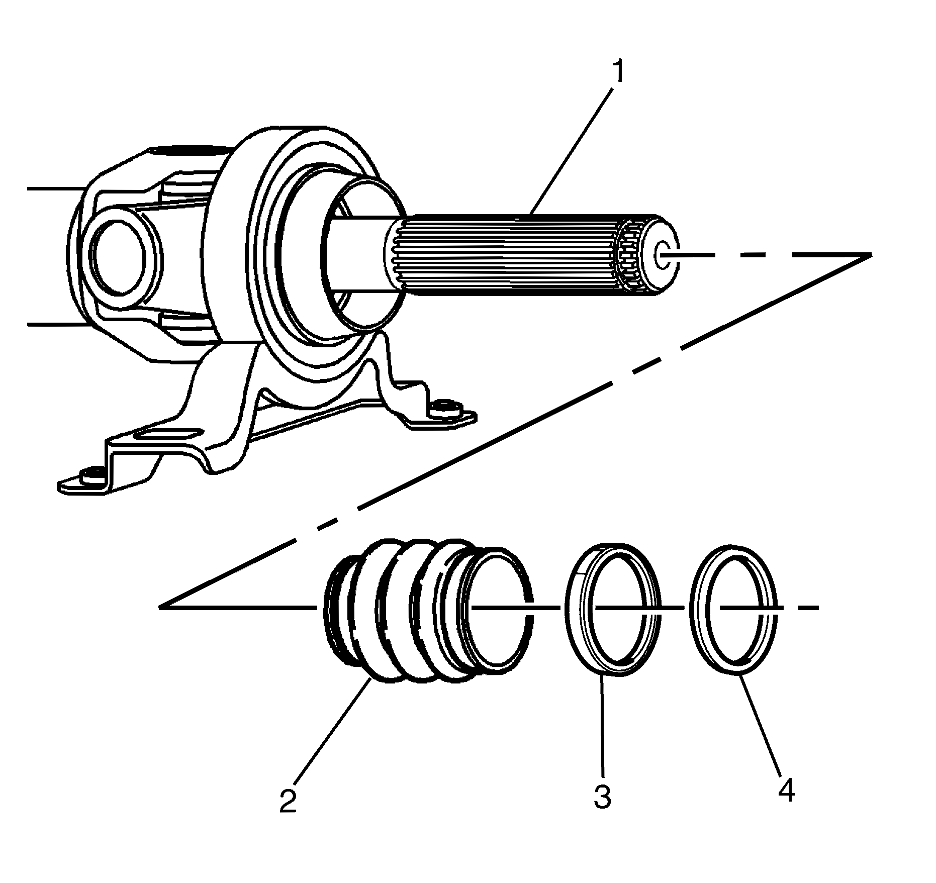
Note: Lubricate the propeller shaft splines (1) with 1-2 grams of molybdenum disulphide grease. Refer to Adhesives, Fluids, Lubricants, and Sealers.
Note: The NEW dust boot clamp (3) must not to be fully tightened at this stage.
Note: The O-ring must be located into the groove on the spline.

Note: Correct alignment during assembly is critical in order to maintain correct balance.
Note: Align the marks on the rear propeller shaft (1) and the front propeller shaft (2) made prior to ensure correct assembly balance.
