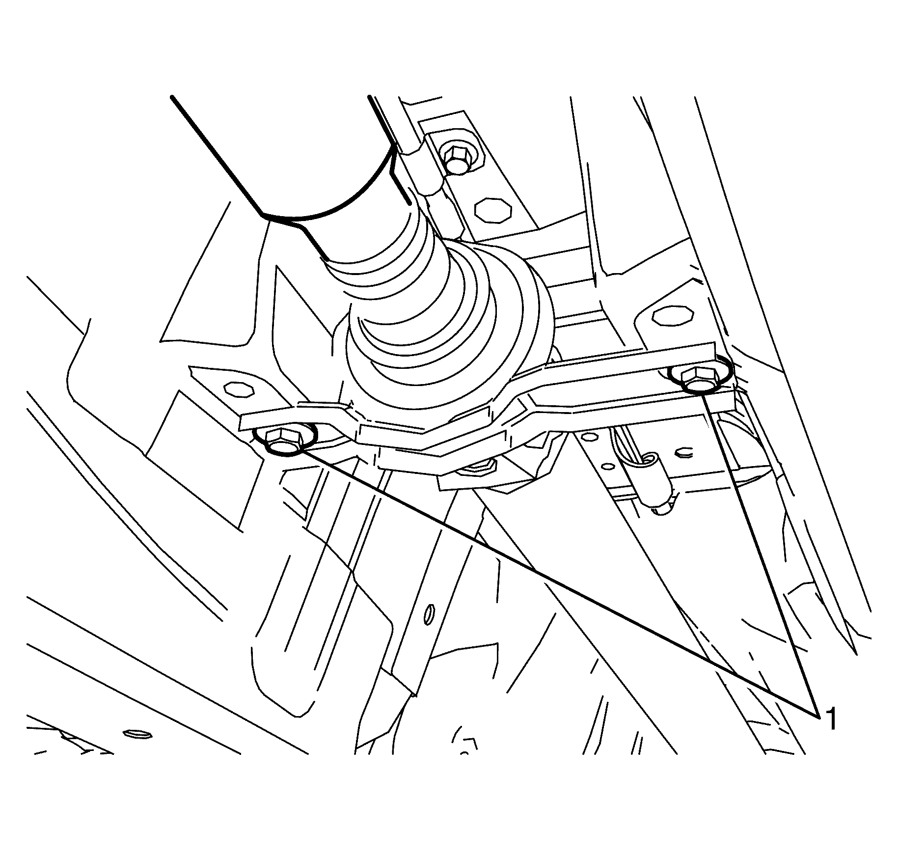
Removal Procedure
- Select park/1st gear position in the transmission and apply the park brake.
- Raise and support the vehicle. Refer to Lifting and Jacking the Vehicle.
- Remove the intermediate exhaust assembly. Refer to Exhaust Crossover Pipe Replacement.
- Remove the propeller shaft heat shield. Refer to Exhaust Heat Shield Replacement - Center.
- Mark the rubber coupling (1) in relation to the differential flange (2).
- Remove the rubber coupling to differential flange retaining bolts (1).
- Mark the rubber coupling (2) in relation to the transmission flange (1).
- Remove the rubber coupling to transmission flange retaining bolts (1) and torque prevailing nuts (2).
- Remove the centre bearing to body retaining bolts (1).
- Disconnect the propeller shaft (2) from the differential flange.
- Remove the propeller shaft (2) from the vehicle.
- Inspect the propeller shaft (2) assembly for excessive wear and/or damage. Inspect the following:
Warning: Refer to Safety Glasses Warning in the Preface section.
Danger: To avoid any vehicle damage, serious personal injury or death when major components are removed from the vehicle and the vehicle is supported by a hoist, support the vehicle with jack stands at the opposite end from which the components are being removed and strap the vehicle to the hoist.
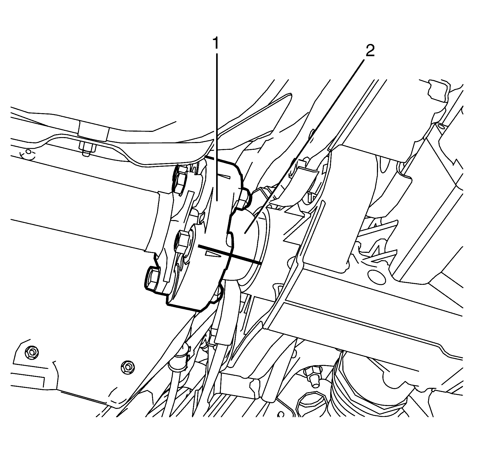
Note: Observe the orientation of the rubber couplings with reference to the differential flange and the transmission flange. This will minimize the potential of incorrect propeller shaft installation.
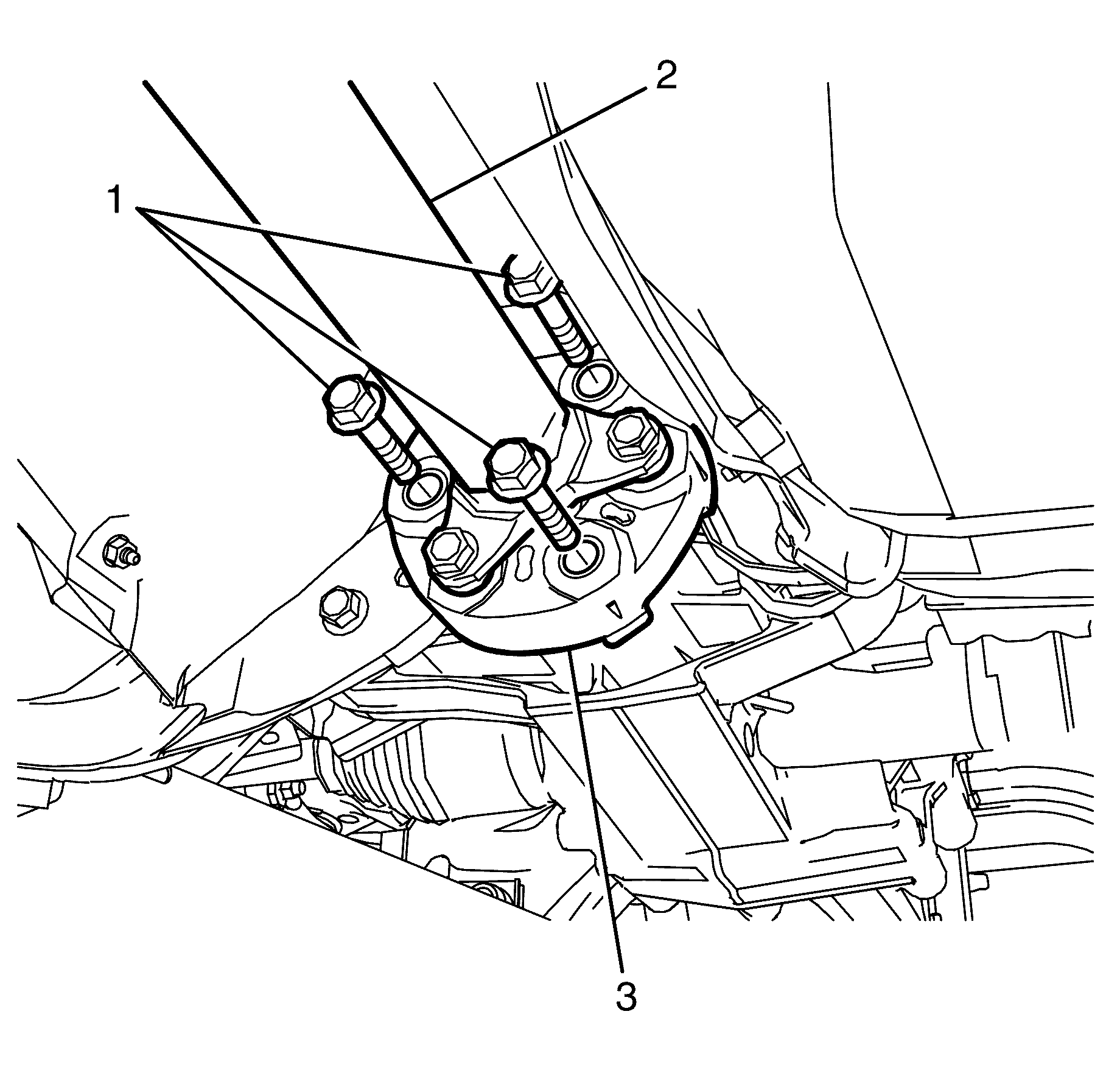
Note: With the aid of an assistant or suitable jack support the propeller shaft (2).
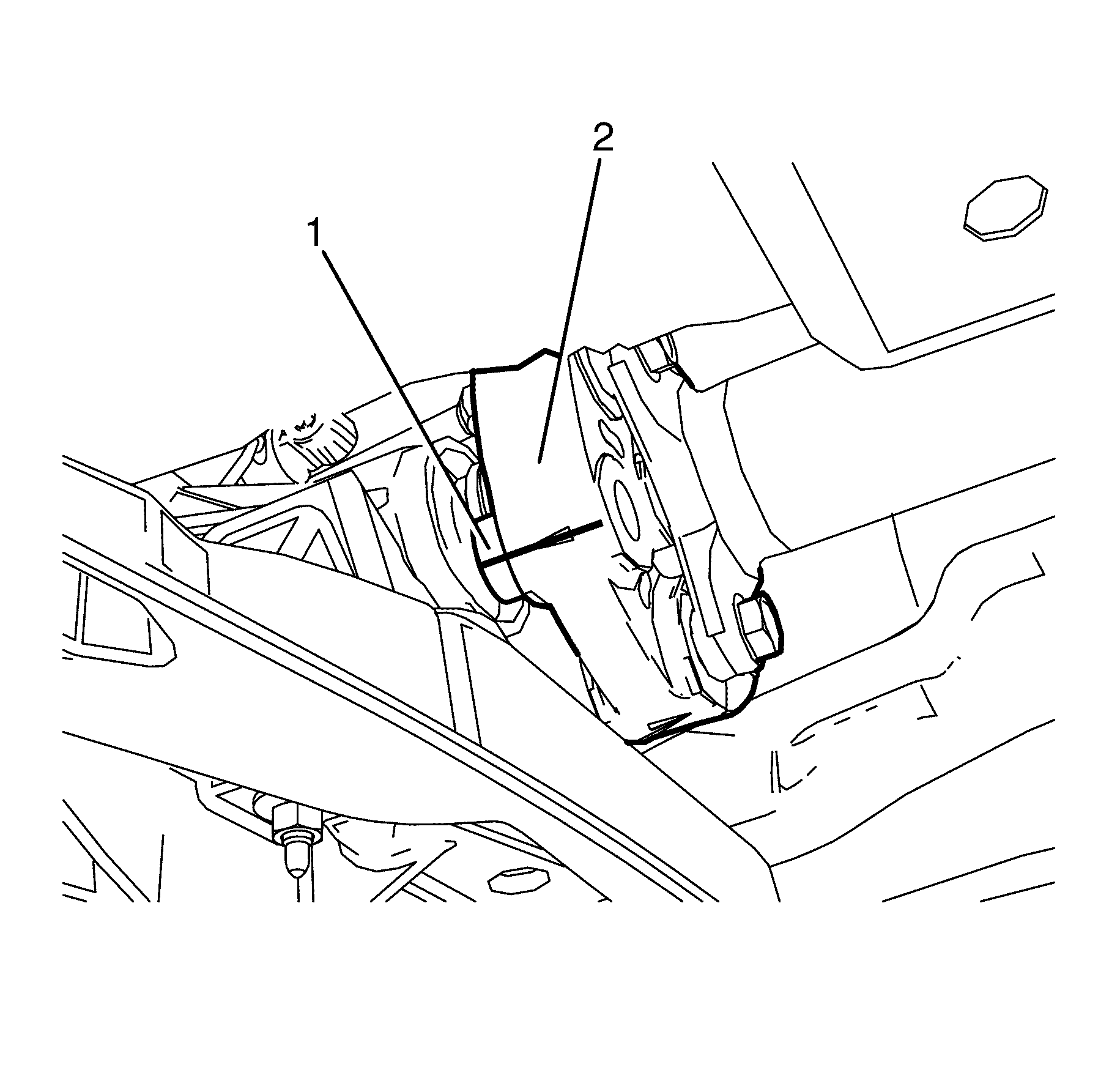
Note: Observe the orientation of the rubber couplings with reference to the differential flange and the transmission flange. This recommendation will minimize the potential of incorrect propeller shaft installation.
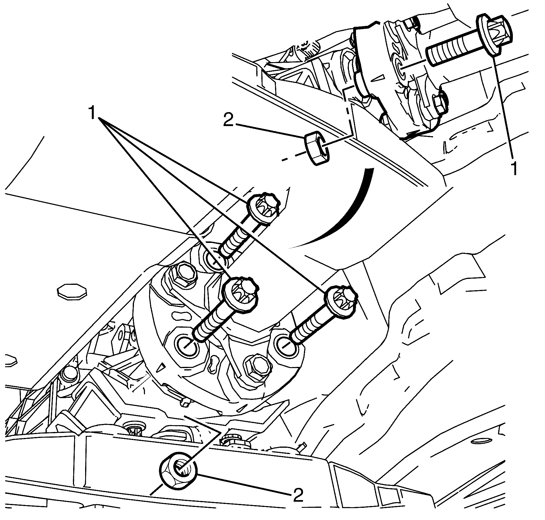
Note: With the aid of an assistant or suitable jack, support the propeller shaft.
Note: Torque prevailing nuts with are single use parts and must be discarded after removal.
Discard the nuts.
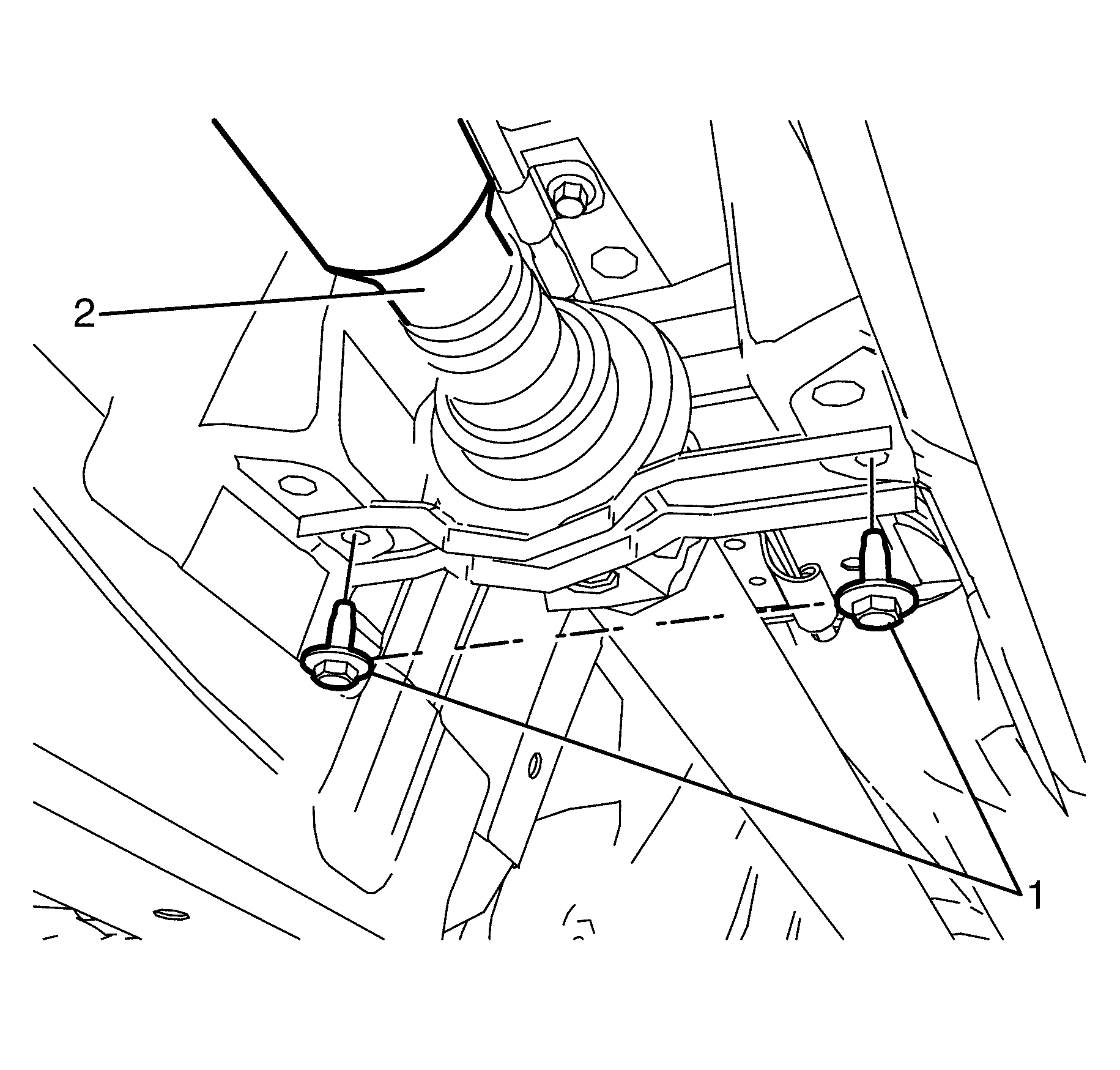
Note: With the aid of an assistant or suitable jack support the propeller shaft (2).
| • | Propeller shaft--For replacement, refer to Propeller Shaft Replacement. |
| • | Rubber coupling--For replacement, refer to Rear Propeller Shaft Coupling Replacement. |
| • | Centre bearing--For replacement, refer to Propeller Shaft Center Support Bearing Replacement. |
| • | Universal joint--For replacement, refer to Universal Joint Replacement. |
Installation Procedure
- Connect the rubber coupling (1) to the differential flange (2).
- Install the rubber coupling to differential flange retaining bolts (1) and tighten to 115 N·m (85 lb ft).
- Connect the rubber coupling (2) to transmission flange (1).
- Install the centre bearing to body retaining bolts (1).
- Install the rubber coupling to transmission flange bolts (1) and NEW torque prevailing nuts (2) and tighten to 100 N·m (72 lb ft).
- Tighten the centre bearing to body retaining bolts (1) and tighten to 22 N·m (16 lb ft).
- Install the propeller shaft heat shield. Refer to Exhaust Heat Shield Replacement - Center.
- Install the intermediate exhaust assembly. Refer to Exhaust Crossover Pipe Replacement.
- Remove the safety stands.
- Lower the vehicle to the ground.
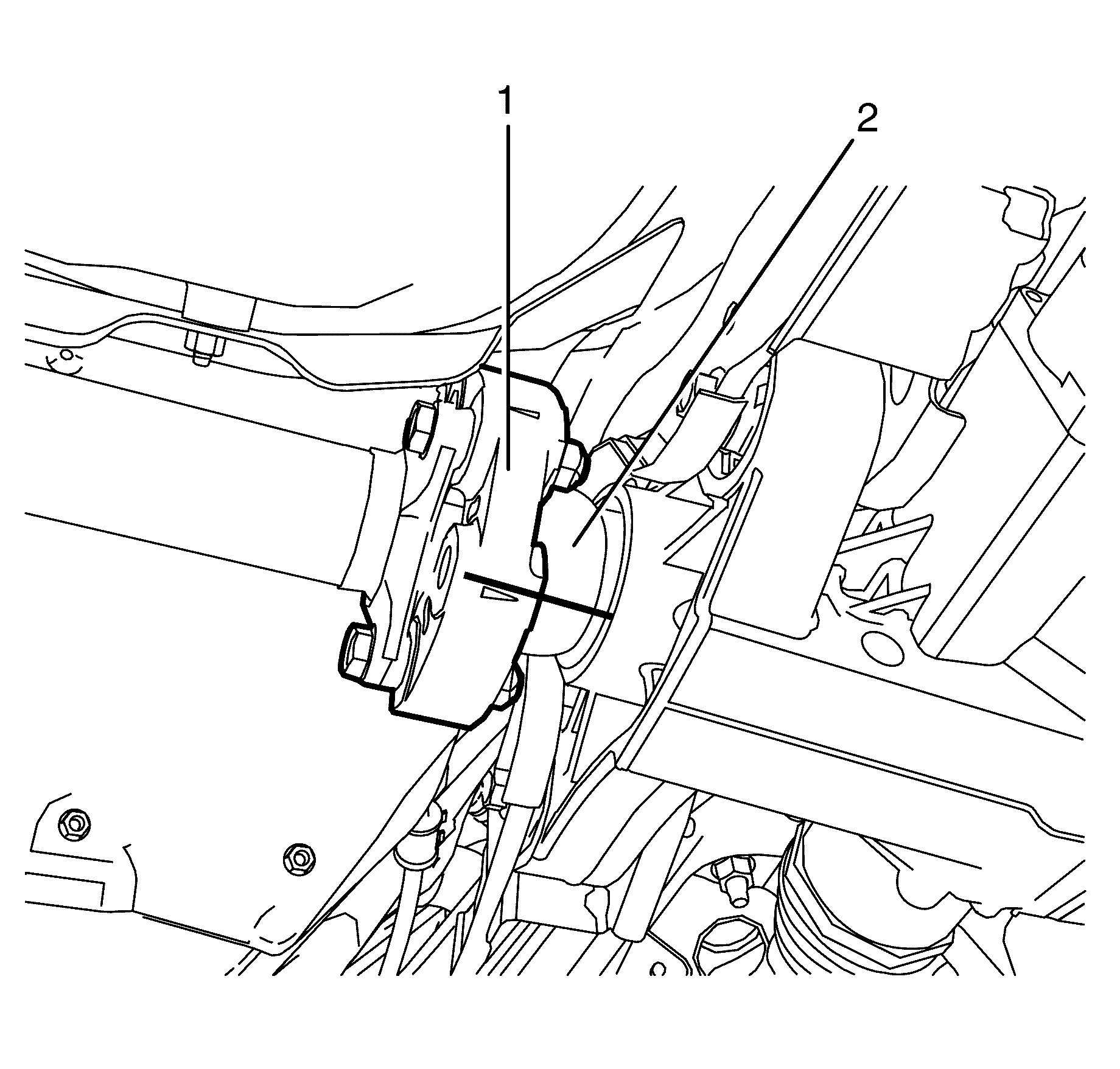
Note: Align the marks on the rubber coupling (1) to differential flange (2) made prior to removal.
Caution: Refer to Fastener Caution in the Preface section.

Note: With the aid of an assistant or suitable jack support the propeller shaft (2) to the differential flange (3).

Note: Align the marks on the rubber coupling (2) to transmission flange (1) made prior to removal.

Note: With the aid of an assistant or suitable jack support the propeller shaft (2).
Note: The centre bearing to body retaining bolts (1) must not be fully tightened at this stage.

Note: With the aid of an assistant or suitable jack support the propeller shaft.
