For 1990-2009 cars only
Removal Procedure
- Remove the master cylinder. Refer to Master Cylinder Replacement .
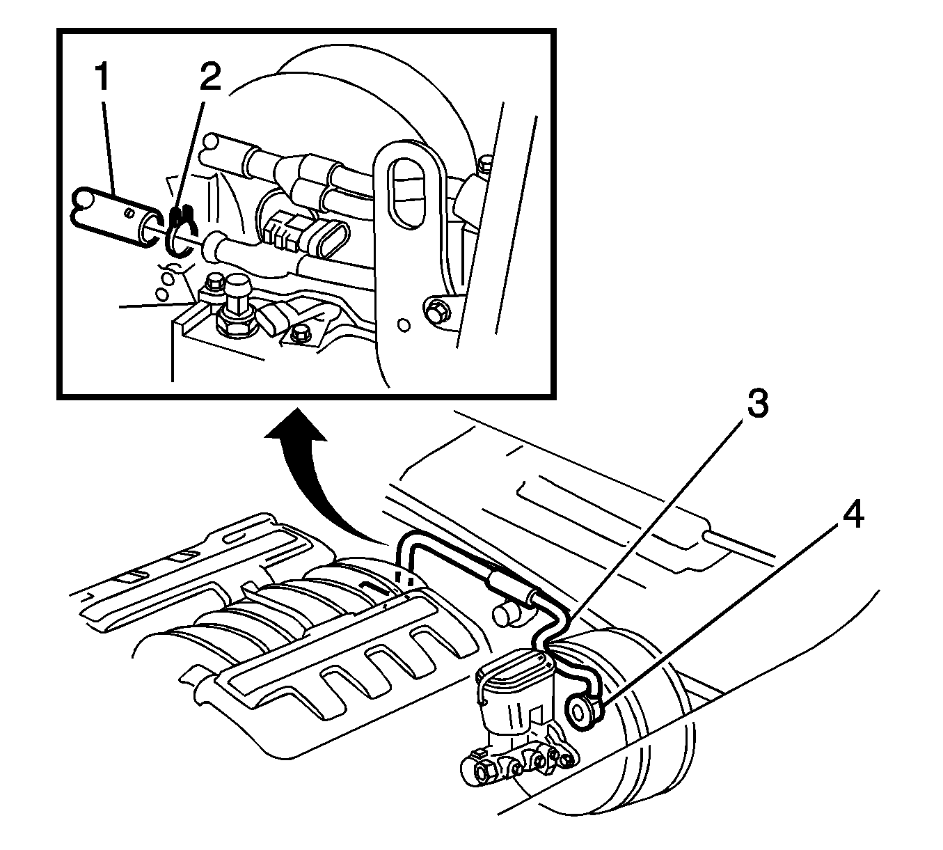
- Compress the hose clamp (4) and move the hose clamp away from the booster fitting.
- Hold the booster fitting and twist the booster hose (3) in order to separate the hose from the fitting.
- Remove the left closeout panel. Refer to Instrument Panel Insulator Panel Replacement - Left Side in Instrument Panel, Gages, and Console.
- Remove the left ventilation ducts. Refer to Instrument Panel Air Outlet Ducts Replacement in Heating, Ventilation, and Air Conditioning.
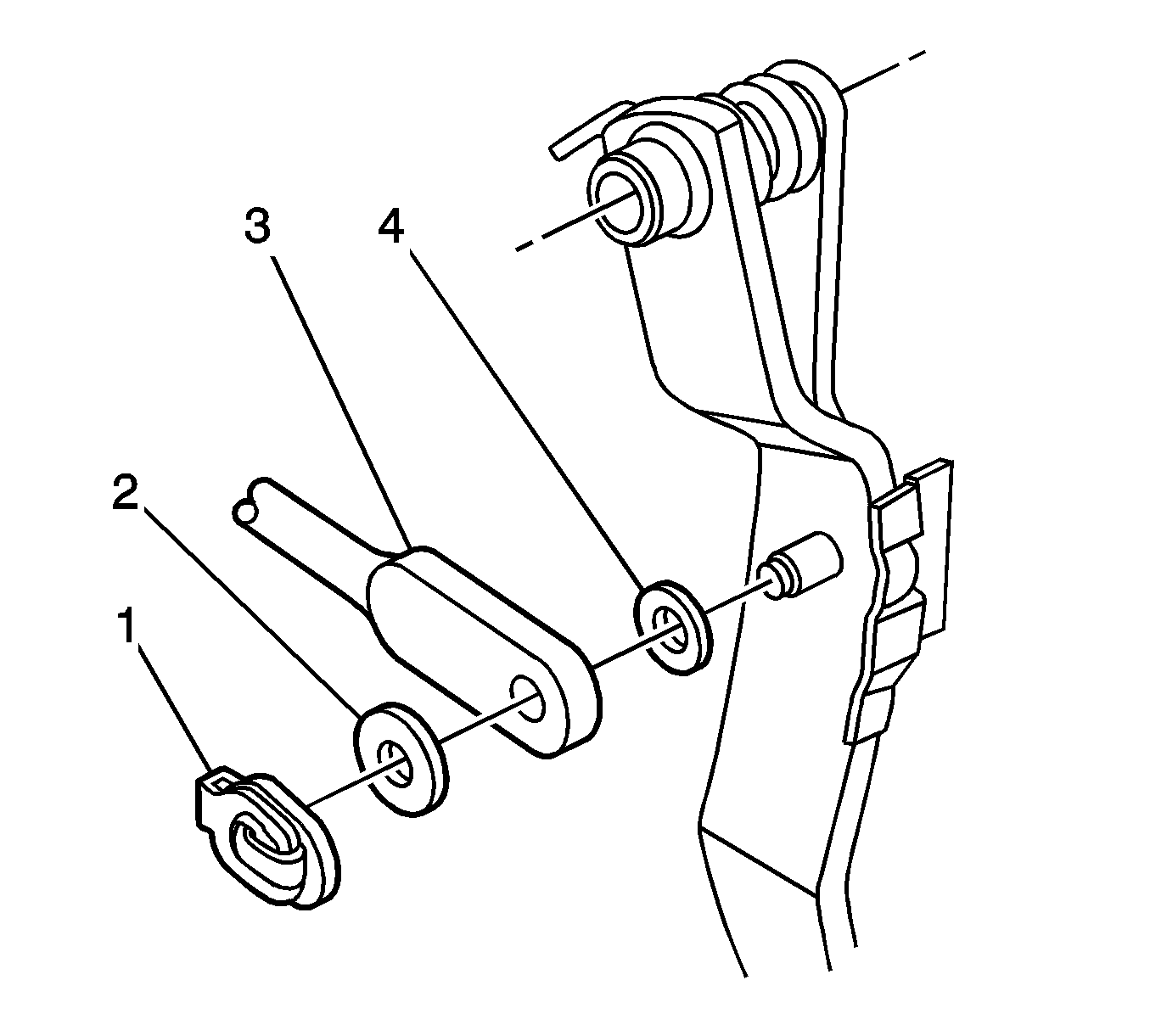
- Remove the push rod retaining clip (1).
- Remove the washer (2).
- Remove the push rod (3) from the brake pedal.
- Remove the washer (4).
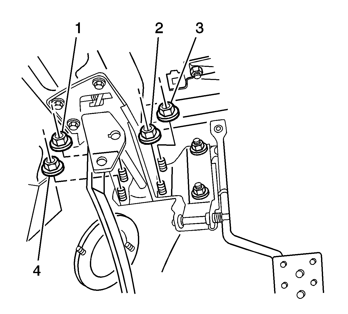
- Remove the vacuum brake booster nuts (1,2,3,4) from the brake pedal bracket.
- Pull the booster toward the engine.
- Remove the booster from the vehicle.


Installation Procedure
- Install the vacuum brake booster to the dash panel.
- Install the nuts (1,2,3,4) in order to retain the booster to the brake pedal bracket.
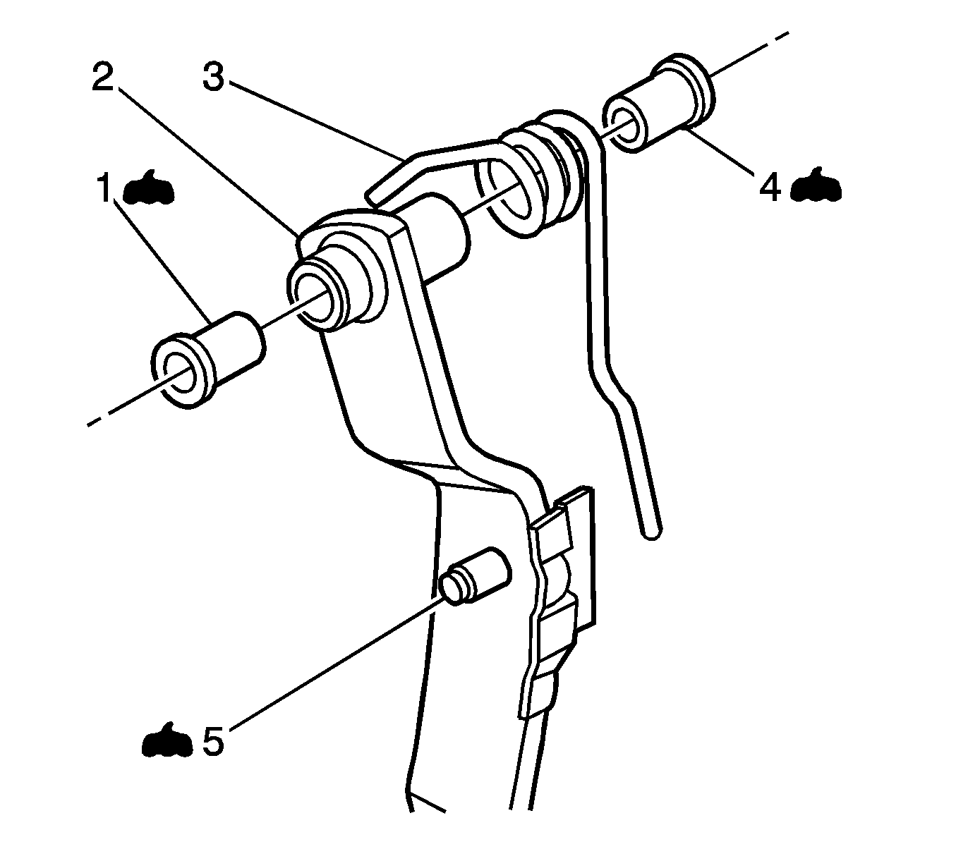
- Apply GM Vehicle Care® Dri-Slide Lubricant, GM P/N 1052948, or the equivalent lithium molybdenum disulphide lubricant, to the pivot point (5) of the push rod on the brake pedal.
- Install the washer (4) to the brake pedal.
- Install the push rod (3).
- Install the washer (2).
- Install the push rod retaining clip (1).
- Install the left ventilation ducts. Refer to Instrument Panel Air Outlet Ducts Replacement in Heating, Ventilation, and Air Conditioning.
- Install the left closeout panel. Refer to Instrument Panel Insulator Panel Replacement - Left Side in Instrument Panel, Gages, and Console.
- Install the booster hose to the booster fitting.
- Compress the hose clamp and move the hose clamp past the wider portion of the fitting. Release the hose clamp on the narrow portion of the fitting in order to retain the hose to the fitting.
- Install the master cylinder. Refer to Master Cylinder Replacement .
Notice: Refer to Fastener Notice in the Preface section.

Tighten
Tighten the nuts to 23 N·m (17 lb ft).


