Tools Required
| • | J 22912-B Split Plate Bearing Puller |
| • | J 23444-A Extreme Press Lubricant ¼ Ounce Tube |
| • | J-42094-A Wheel Hub Remover and Installer |
Removal Procedure
- Remove the rear suspension lower control arm from the vehicle. Refer to Lower Control Arm Replacement in Rear Suspension.
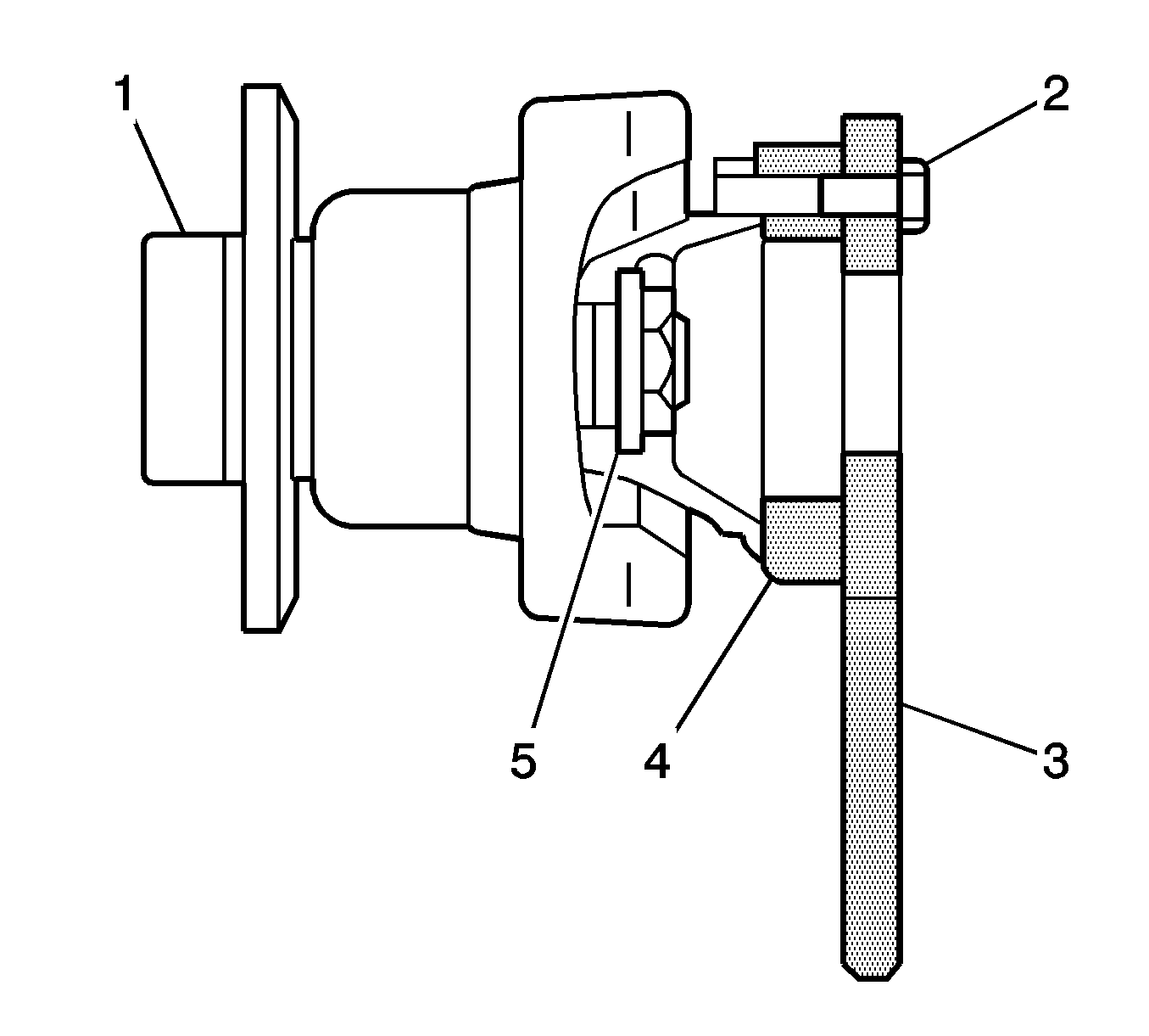
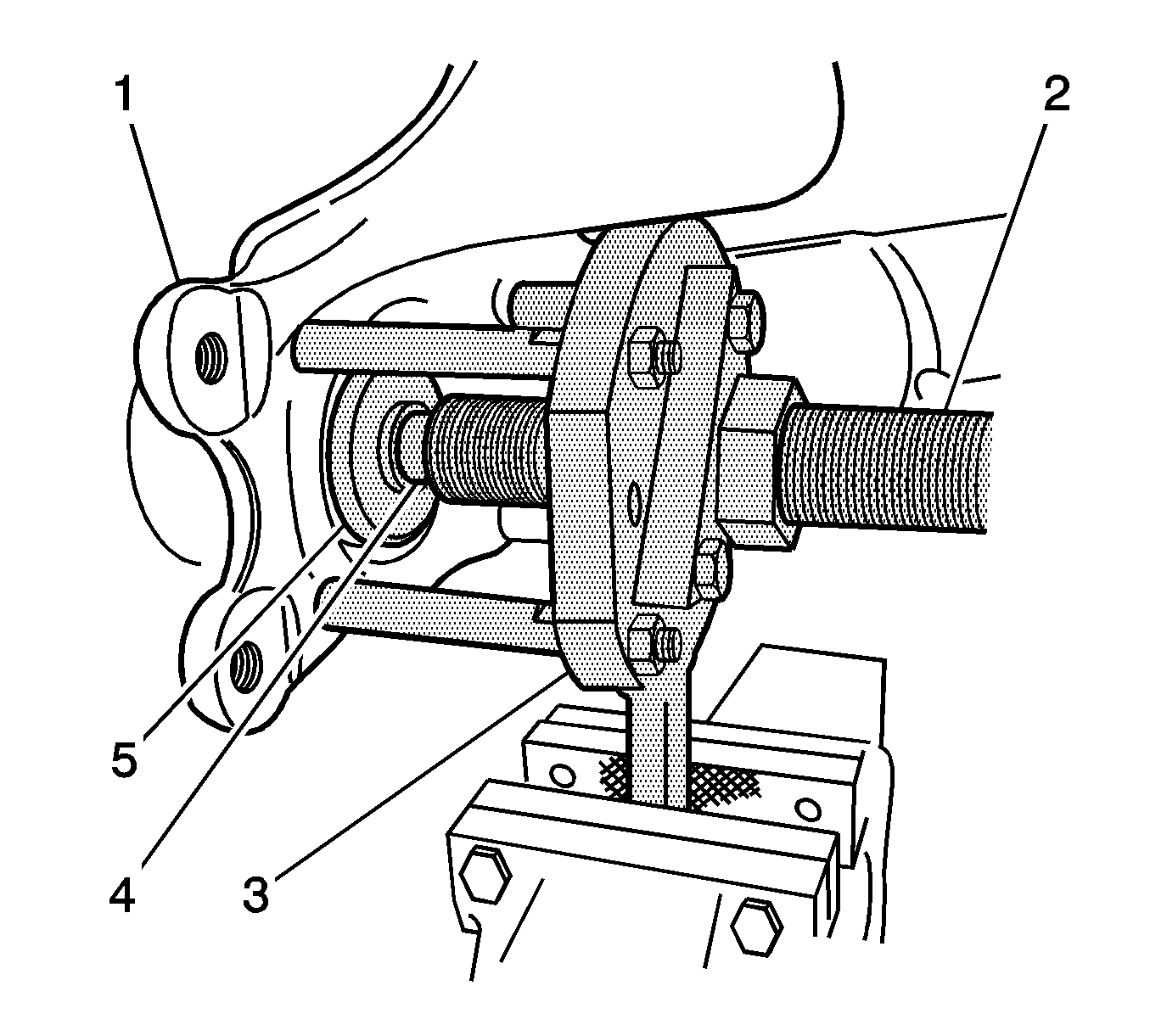
- From the J-42094-A kit, align the holes in the J-42094-2 (4) with the holes in the rear wheel drive shaft flange.
- Align the holes in the J-42094-1-B (3) marked "B" with the holes in the J-42094-2 and the holes in the flange.
- Install the outer constant velocity joint bolts (2) in order to retain the J-42094-2 and the J-42094-1-B to the flange.
- Unstake the hub nut retainer (5).
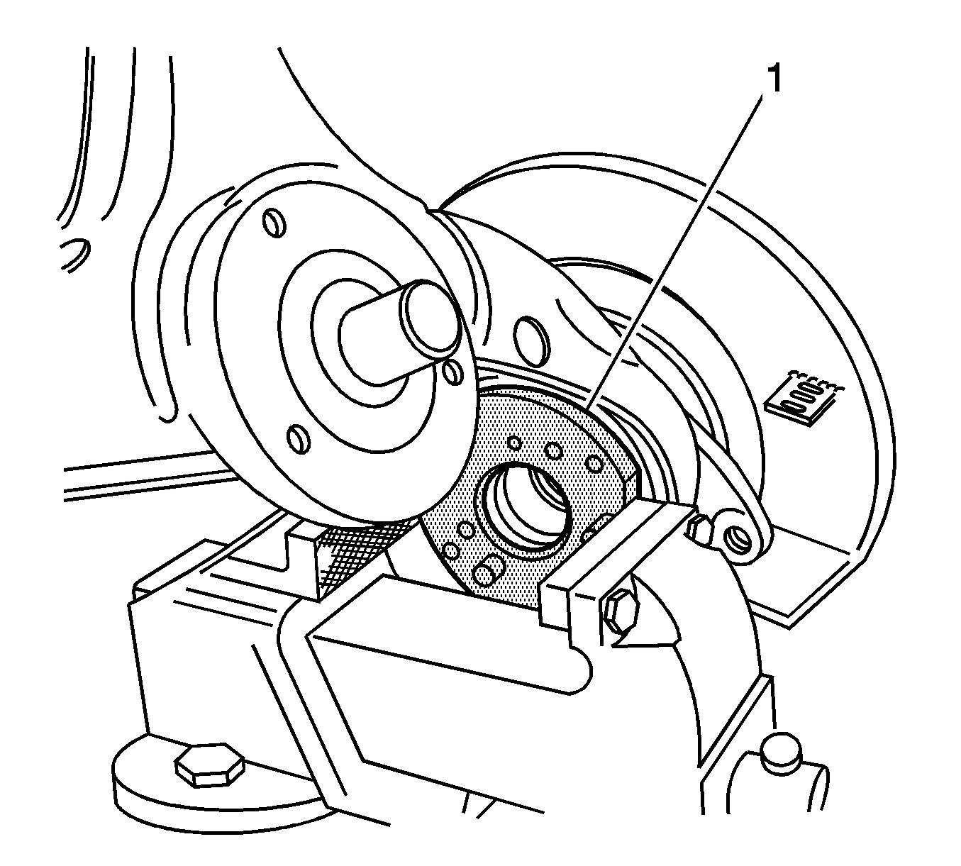
- Use a vise in order to hold the J-42094-1-B (1).
- Remove and discard the hub nut retainer.
- Remove and discard the hub nut.
- Remove the J-42094-1-B from the vise, but leave the tools on the assembly.
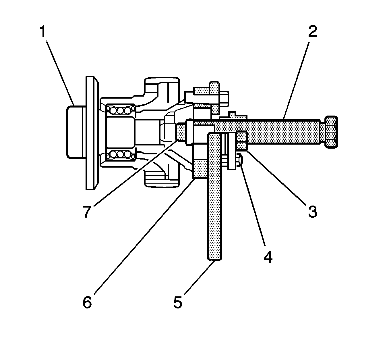
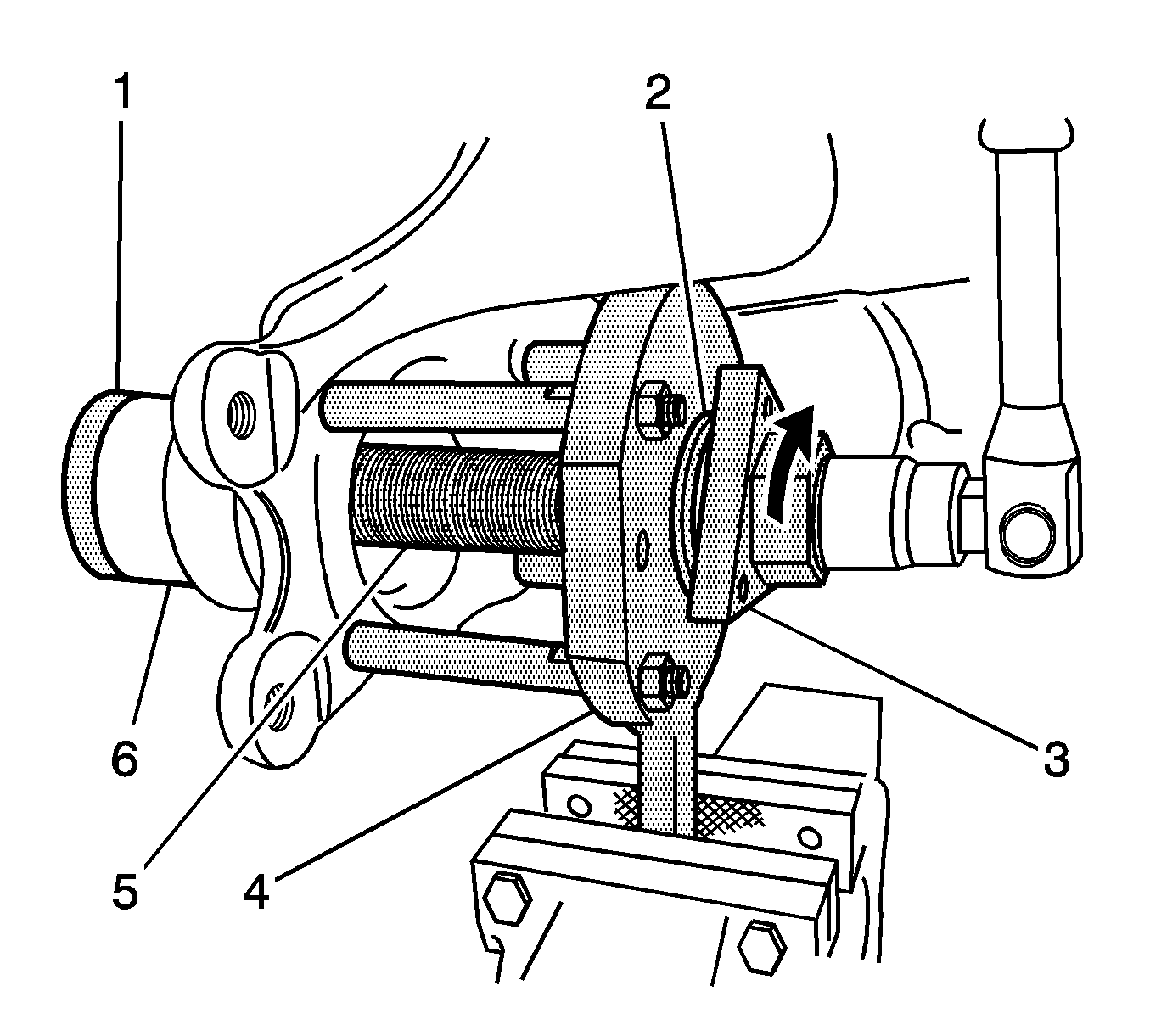
- Lubricate the threads of the J-42094-3 (2) with J 23444-A .
- Install the J-42094-3 to the J-42094-4-A (3).
- Lubricate the ball end of the J-42094-5-B (7) with J 23444-A .
- Install the J-42094-5-B to the end of the J-42094-3.
- Install the J-42094-4-A and the 3 bolts (6) to the J-42094-1-B.
- Adjust the position of the J-42094-3 in the J-42094-4-A in order to allow the J-42094-4-A to be in full contact with the J-42094-1-B.
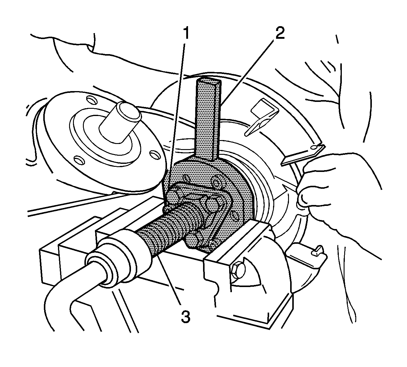
- Ensure the J-42094-1-B (2) is secure in a vise.
- Use an assistant to hold and support the control arm assembly.
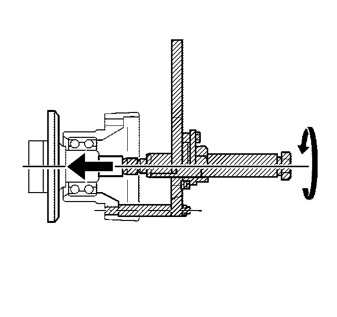
- Turn the J-42094-3 (3) in order to remove the rear wheel drive shaft flange from the hub assembly.
- Remove the tools from the flange.
- Remove the 2 TORX bolts (1, 8) and the 2 washers (2, 3) from the brake backing plate shield (4).
- Remove the 2 bolts (6, 7).
- Use a M10 X 1.25 bottoming tap and a suitable lubricant in order to clean the threads (4, 5, 7, 8) in the control arm.
- Install 2 J-42094-7-A supports (1, 6) to the control arm, in the 2 shallowest control arm to shield bolt holes, near the caliper mounting holes.
- Install the J-42094-7-AUS-2 (2) support to the control arm, in the deepest control arm to shield bolt hole.
- Install the J-42094-7-AUS-1 (3) support to the control arm, in the remaining control arm to shield bolt hole.
- Ensure the 4 supports are in the correct positions in order to attach to the flat surface of the J-42094-1-B.
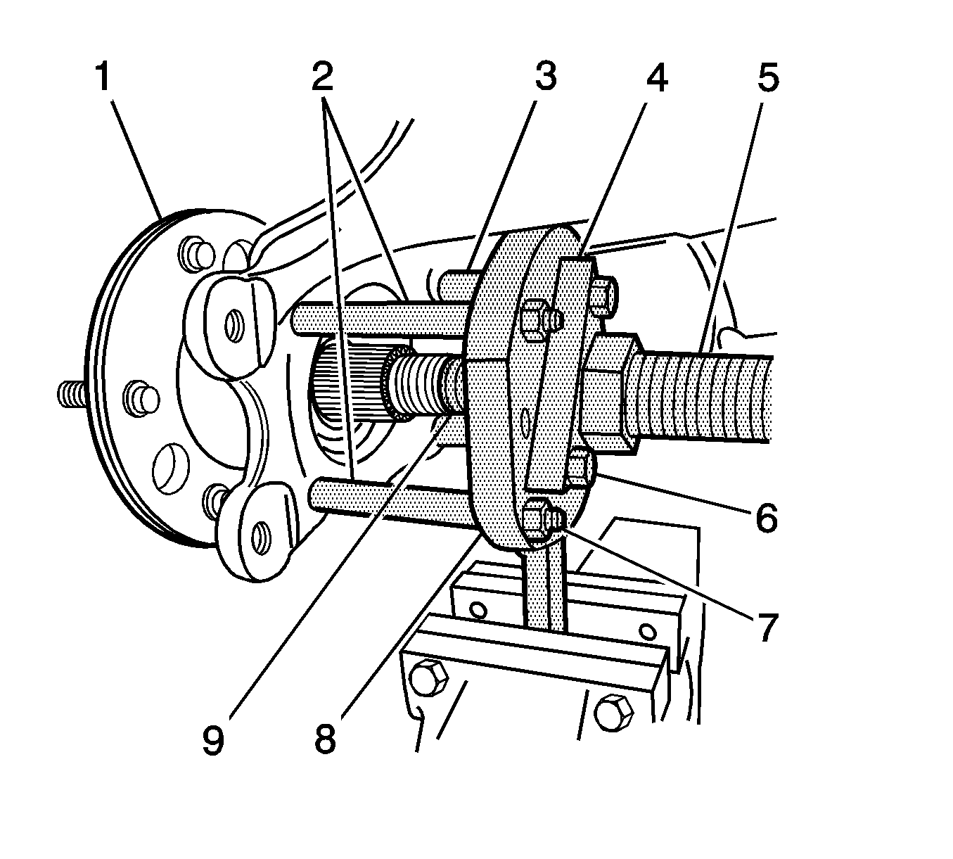
- Attach the J-42094-1-B (8) to the 4 supports (2, 3).
- Install the 4 nuts in order to retain the J-42094-1-B to the supports.
- Install the J-42094-3 (5) to the J-42094-4-A (4).
- Lubricate the ball end of the J-42094-5-B (9) with J 23444-A .
- Install the J-42094-5-B to the end of the J-42094-3.
- Install the J-42094-5-B and the J-42094-3 through the center hole in the J-42094-1-B.
- Install the J-42094-4-A and the 3 bolts (6) to the J-42094-1-B.
- Adjust the position of the J-42094-3 in the J-42094-4-A in order to allow the J-42094-4-A to be in full contact with the J-42094-1-B.
- Ensure the handle of the J-42094-1-B is secure in a vise.
- Use an assistant to hold and support the control arm assembly.
- Turn the J-42094-3 in order to press out the rear wheel hub.
- Remove the hub and the bearing outside inner race from the control arm.
- Turn the J-42094-3 away from the bearing, but leave the tools on the assembly.
- Remove the shield and the park brake anchor bracket as an assembly from the control arm.
- If you are NOT replacing the hub, remove the bearing outside inner race (3) from the hub (2).
- Use snap ring pliers in order to remove the retainer from the wheel bearing in the control arm.
- Install the J-42094-6 (5) to the end of the J-42094-5-B (4).
- Turn the J-42094-3 (2) in order to press out the bearing from the control arm.
- Discard the wheel bearing.
- Clean the bearing bore in the control arm.
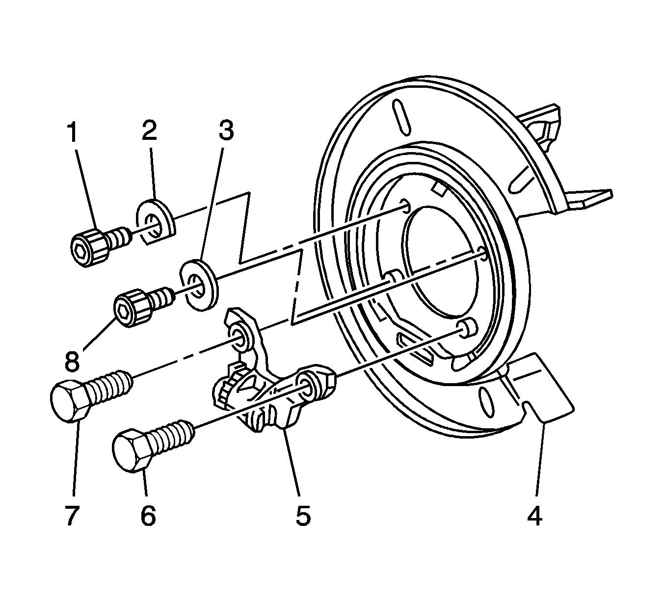
Important: Ensure the park brake adjuster anchor bracket assembly (5) remains on the shield.
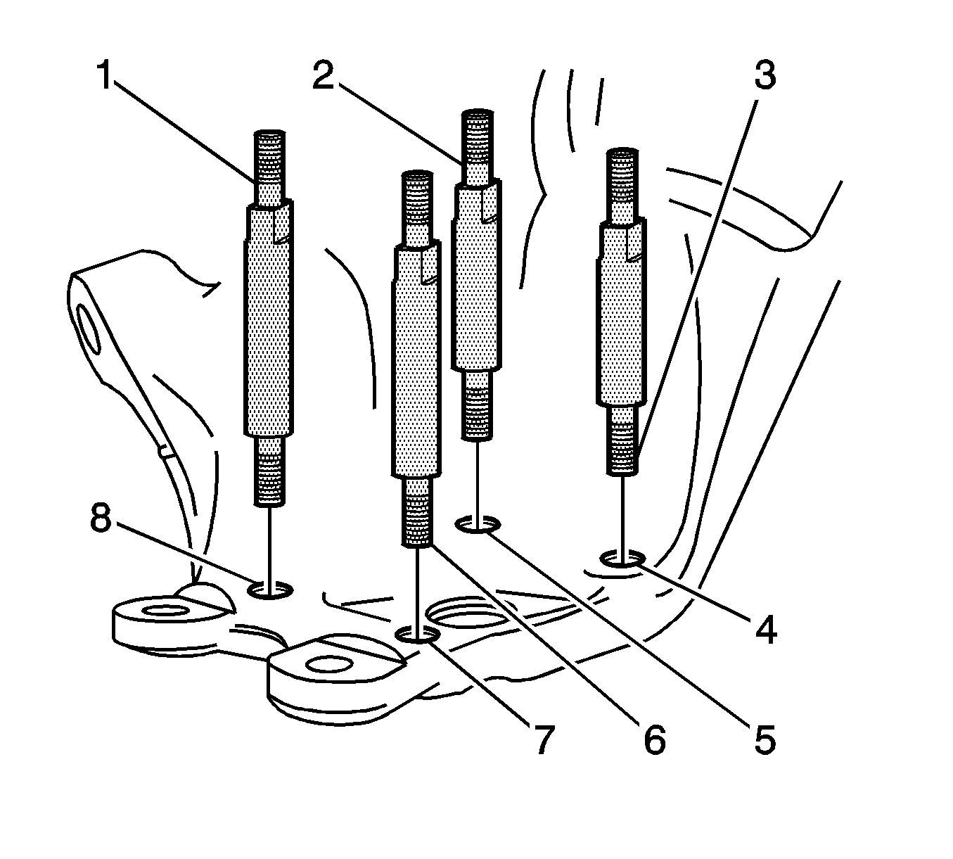
Clean the threads from the inboard side to the outboard side.
Repair the threads if necessary.
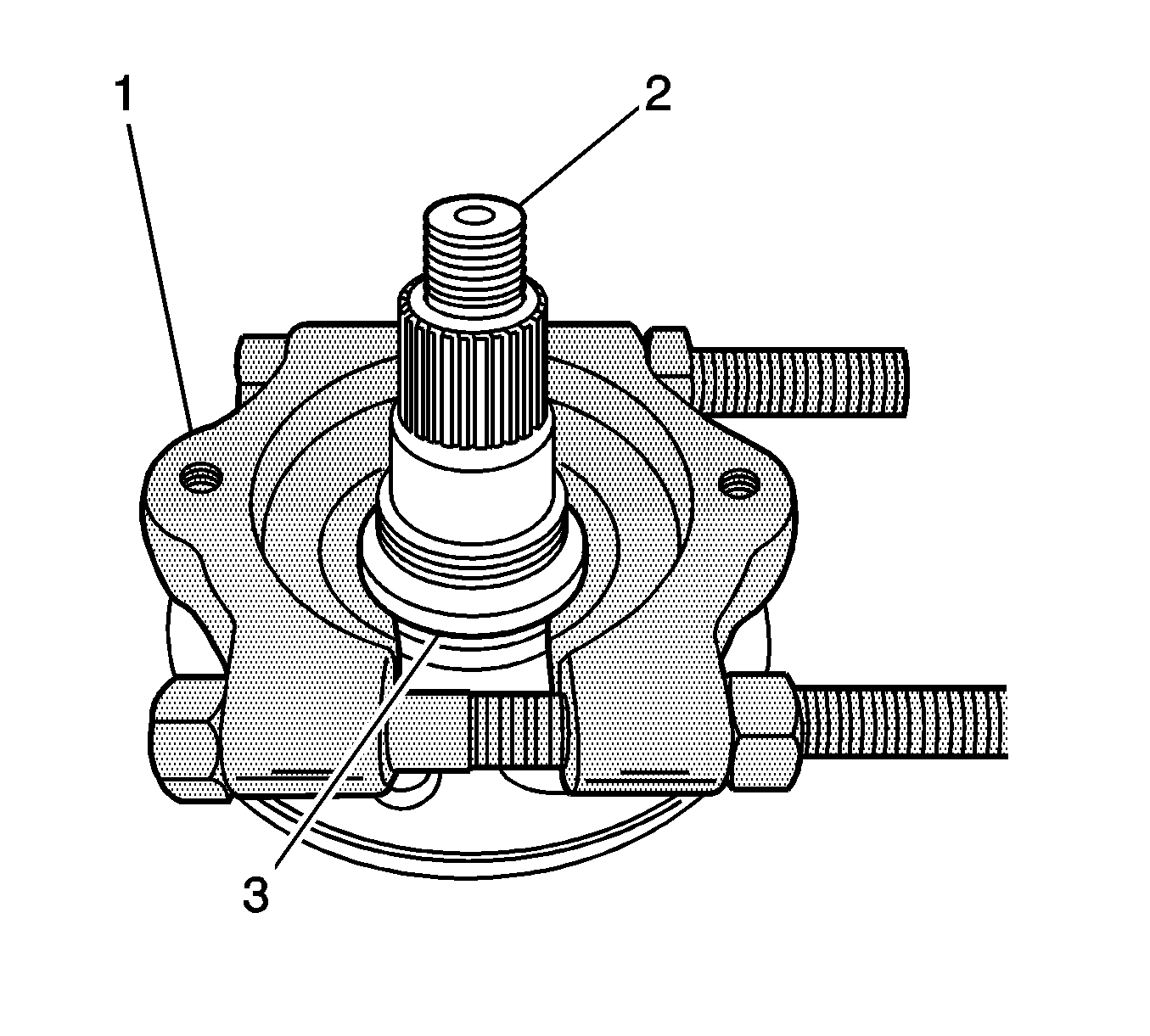
Use the J 22912-B (1), or equivalent, and a press in order to remove the race from the hub.
Installation Procedure
- Ensure the bearing bore in the control arm is clean and free of foreign matter.
- Apply GM Vehicle Care Wheel Bearing Lubricant, GM P/N 1051344, or the equivalent lithium lubricant, to the bearing bore in the control arm.
- Apply GM Vehicle Care Wheel Bearing Lubricant, GM P/N 1051344, or the equivalent lithium lubricant, to the outside of the outer races of a NEW wheel bearing.
- Remove the bolts retaining the J-42094-4-A (3) to the J-42094-1-B (4).
- Remove the J-42094-4-A and the J-42094-3 (5).
- Apply GM Vehicle Care Wheel Bearing Lubricant, GM P/N 1051344, or the equivalent lithium lubricant, to the outside of the outer race of the J-42094-10 (2) ball bearing.
- Install the J-42094-10 to the flanged end of the J-42094-4-A.
- Install the J-42094-10 and the J-42094-4-A to the J-42094-1-B.
- Install the J-42094-3 to the J-42094-1-B.
- Install a NEW wheel bearing (6) to the J-42094-8-A (1).
- Position the wheel bearing on the wheel bearing bore in the control arm.
- Engage a minimum of 8 threads of the J-42094-3 with the J-42094-8-A.
- Use a breaker bar in order to hold the J-42094-3.
- Rotate the J-42094-4-A in order to press the wheel bearing into the control arm.
- Remove the J-42094-8-A from the bearing.
- Use snap ring pliers in order to install the bearing retainer to the control arm.
- Remove the tools from the control arm.
- Install the rear disc brake backing plate shield (4) and the park brake anchor bracket assembly (5) to the control arm.
- Install the 2 TORX bolts (1, 8) and the 2 washers (2, 3) to the shield.
- Apply LOCTITE 242, or equivalent, to the threads of the 2 bolts (6, 7).
- Install the 2 bolts to the anchor bracket.
- Use a bearing driver collar (4) and press plates in order to support the outside end of the hub (5) on a hydraulic press.
- Position the control arm (1) and the wheel bearing on the hub.
- Use an assistant to hold and support the control arm assembly.
- Place the J-42094-9-A (3) on the bearing inside inner race.
- Place a steel pipe (2), or equivalent, on the J-42094-9-A.
- Use the hydraulic press in order to install the hub to the wheel bearing.
- Remove the steel pipe, or equivalent.
- Remove the J-42094-9-A from the bearing.
- Position the J-42094-2 (5) on the rear wheel drive shaft flange.
- Position the J-42094-1-B (1) on the J-42094-2.
- Install the outer constant velocity joint bolts (4) in order to retain the J-42094-2 and the J-42094-1-B to the flange.
- Apply GM Vehicle Care Wheel Bearing Lubricant, GM P/N 1051344, or the equivalent lithium lubricant, to the splines on the flange.
- Apply GM Vehicle Care Wheel Bearing Lubricant, GM P/N 1051344, or the equivalent lithium lubricant, to the threads on the inside end of the hub.
- Align the splines on the flange with the splines on the hub.
- With the outside end of the hub on the collar and the press plates, position the flange on the inside end of the hub.
- Place the J-42094-9-A (2) on the flange.
- Place a steel pipe (3), or equivalent, on the J-42094-9-A.
- Use the press in order to install the flange to the hub and bearing assembly.
- Remove the steel pipe, or equivalent.
- Remove the J-42094-9-A from the flange.
- With the J-42094-2 and the J-42094-1-B on the flange, remove the control arm from the press.
- Use a vise in order to hold the J-42094-1-B.
- Install a NEW hub nut to the inside end of the hub.
- Remove the J-42094-1-B and the control arm assembly from the vise.
- Remove the bolts from the J-42094-1-B.
- Remove the J-42094-2 and the J-42094-1-B from the control arm assembly.
- Install the NEW hub nut retainer.
- Stake the retainer to the nut.
- Install the rear suspension lower control arm to the vehicle. Refer to Lower Control Arm Replacement in Rear Suspension.
Important: Do not install the J-42094-4-A to the bolts on the J-42094-1-B.
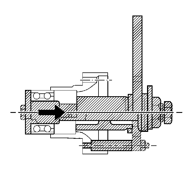
Ensure the wheel bearing is seated properly in the control arm.

Notice: Refer to Fastener Notice in the Preface section.
Align the cut edge of the washers with the surface of the hub.
Tighten
Tighten the bolts to 75 N·m (55 lb ft).
Tighten
Tighten the bolts to 88 N·m (65 lb ft).
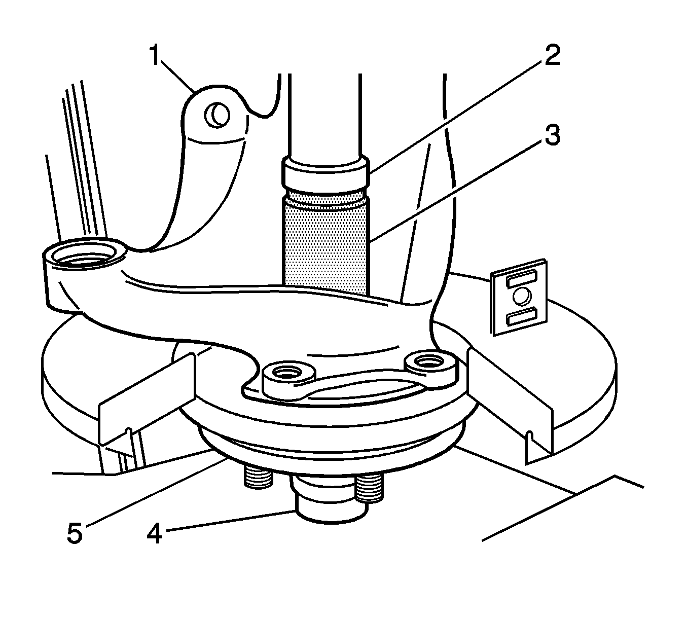
Ensure the weight of the hub is on the outside end of the hub and not on the wheel studs.
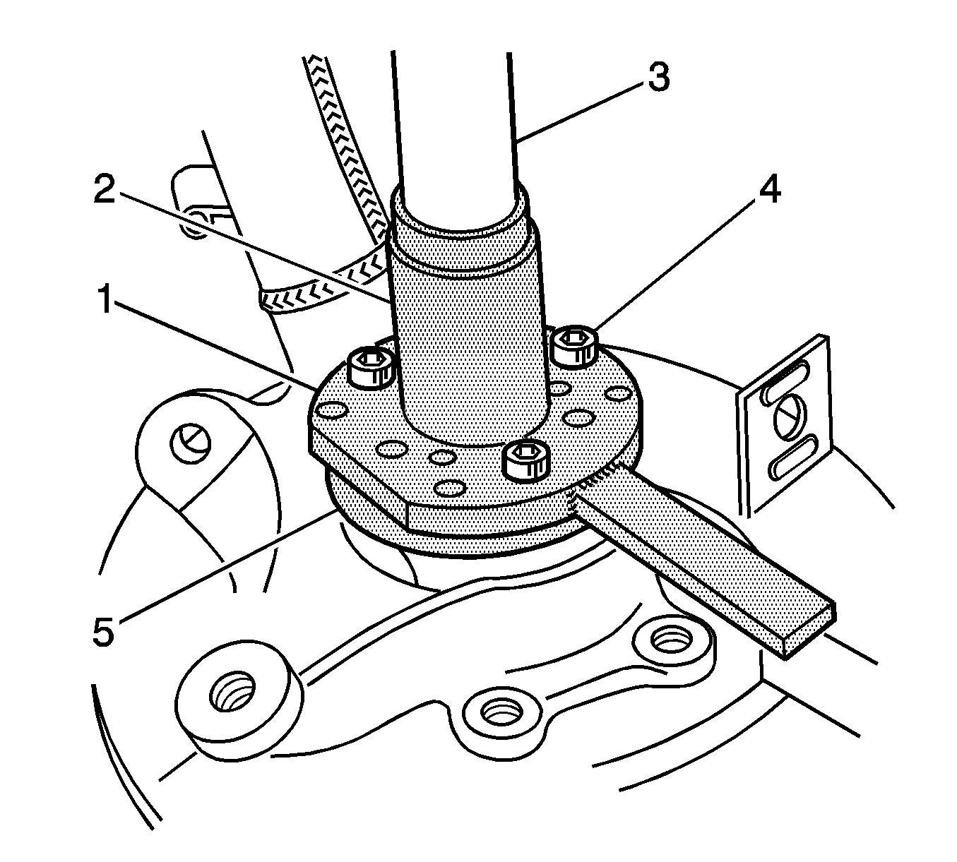
Tighten
Tighten the nut to 300 N·m (221 lb ft).
