Tools Required
| • | J 6627-A Tie Rod Puller |
| • | J 41013 Rotor Resurfacing Kit |
| • | J 42066 Rear Hub Holding Tool |
| • | J 42450-A Wheel Hub Resurfacing Kit |
| • | J 45059 Angle Meter |
| • | CH-46839 Rear Crossmember Centering Tool |
Removal Procedure
- Raise and support the vehicle on an alignment rack. Refer to Lifting and Jacking the Vehicle in General Information.
- Remove the rear tire and wheel assemblies. Refer to Tire and Wheel Removal and Installation in Tires and Wheels.
- Remove the 2 mufflers. Refer to Muffler Replacement in Engine Exhaust.
- Loosen the 6 bolts that retain the 2 rear suspension support braces to the body.
- Loosen the 2 bolts that retain the rear suspension support to the body.
- Loosen the nut that retains the stabilizer shaft to the shaft link.
- Remove the nut and the bolt that retain the stabilizer shaft link to the lower control arm.
- Loosen the nut that retains the outer adjustment link to the control arm.
- Use the J 6627-A , or equivalent, in order to separate the outer adjustment link stud from the control arm.
- Remove and discard the nut from the outer adjustment link stud.
- Position the adjustment link assembly away from the control arm.
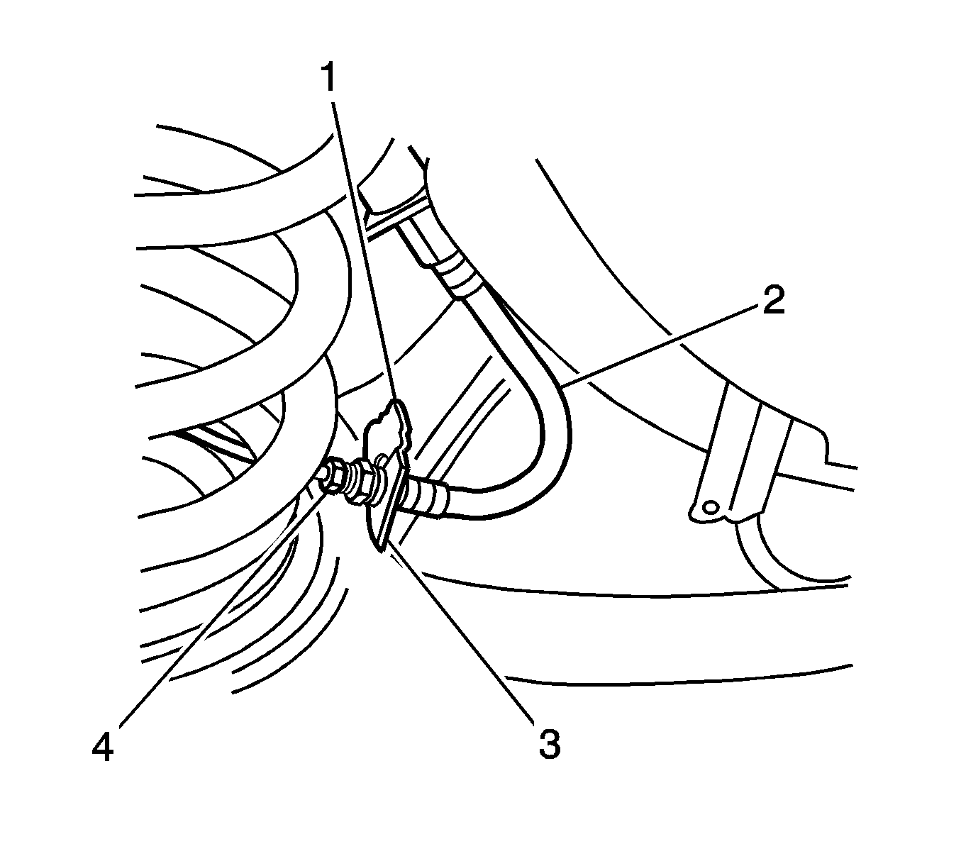
- Remove the clip (1) from the brake hose (2).
- Pull the brake pipe and hose forward from the bracket.
- Lift the brake pipe up through the slot in the bracket in order to separate the brake pipe and hose from the control arm.
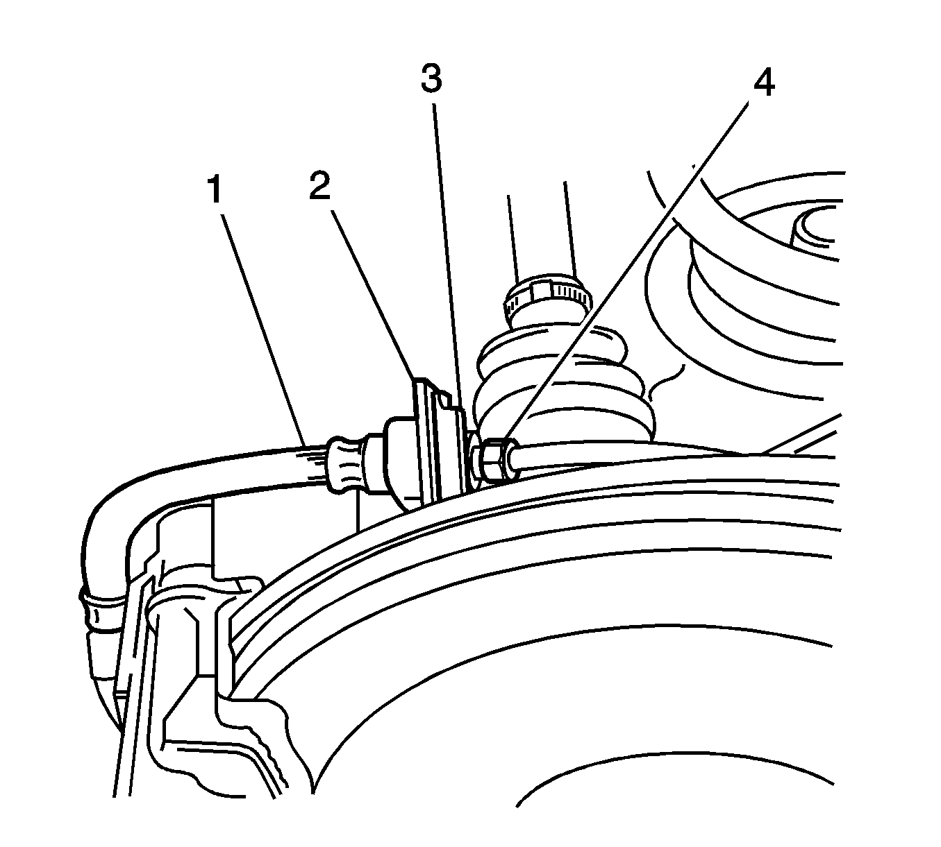
- Loosen the brake pipe flare nut (4).
- Remove the clip (3) from the backing plate bracket (2).
- Remove the brake pipe from the brake hose (1).
- Plug the brake hose in order to minimize fluid loss and contamination.
- Remove the brake pipe from the backing plate bracket.
- Plug the brake pipe.
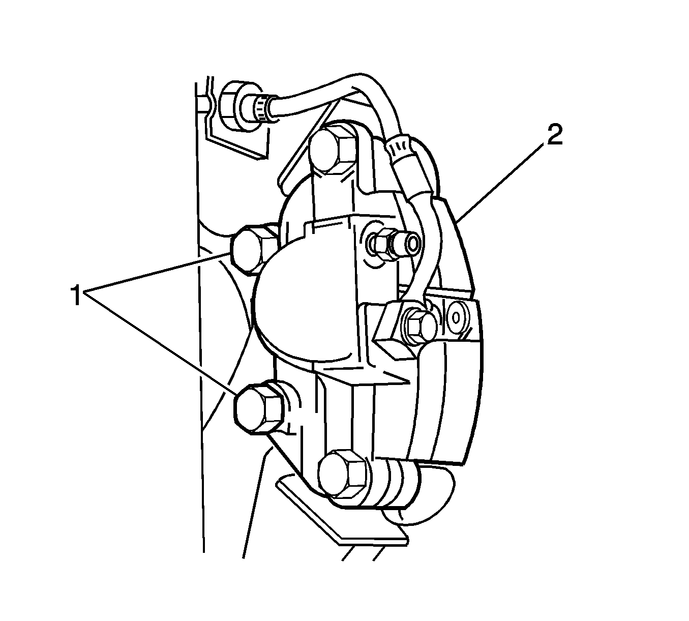
- Remove the 2 bolts and the brake caliper and bracket assembly from the control arm.
- Remove the rear park brake cable. Refer to Parking Brake Rear Cable Replacement - Left Side or to Parking Brake Rear Cable Replacement - Right Side in Park Brake.
- If necessary for sufficient access, remove the propeller shaft. Refer to Two-Piece Propeller Shaft Replacement in Propeller Shaft.
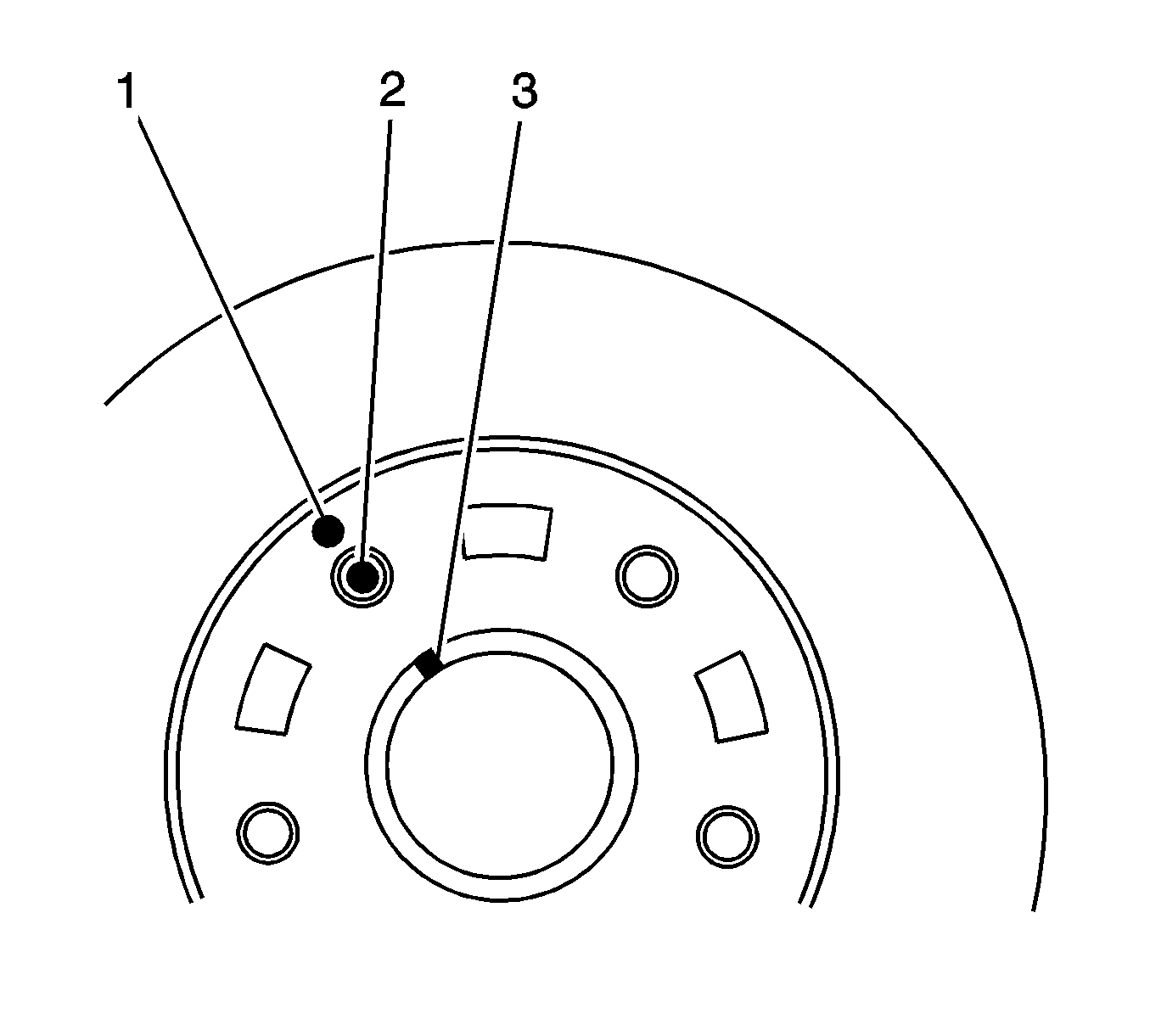
- Use paint in order to mark the position of the brake rotor (1) to the wheel stud (2) and to the hub (3).
- Remove the brake rotor from the hub. If the brake rotor does not slide off the hub easily, complete the following steps:
- Install the J 42066 , or the equivalent tool, and 2 wheel nuts onto 2 studs in order to prevent the hub from turning.
- Tie wire to the upper shock mount and to the wheel drive shaft (1) in order to support the wheel drive shaft.
- Remove the bolts (2) and the retaining plates that retain the outer constant velocity joint to the drive shaft flange.
- Separate the wheel drive shaft from the drive shaft flange.
- Position a jack with a block of wood under the control arm.
- Raise the jack slightly in order to reduce the spring load on the control arm.
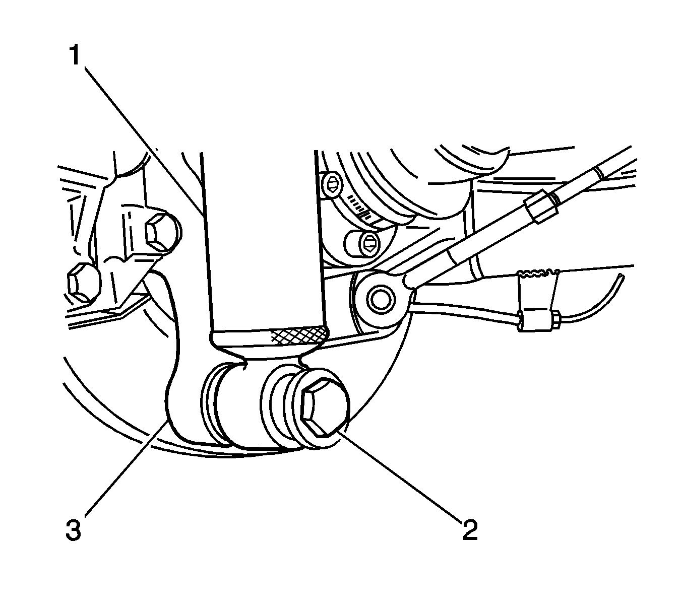
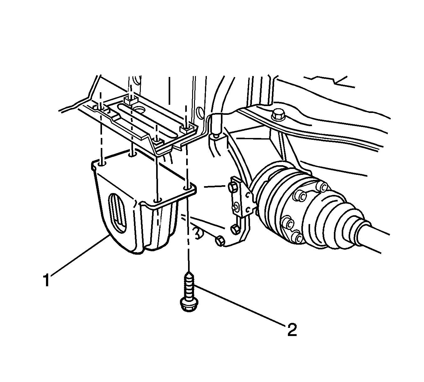
- Remove the bolt (2) and the washer from the shock absorber (1).
- Separate the shock absorber from the control arm (3).
- Lower the jack and the control arm.
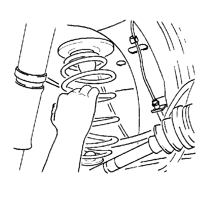
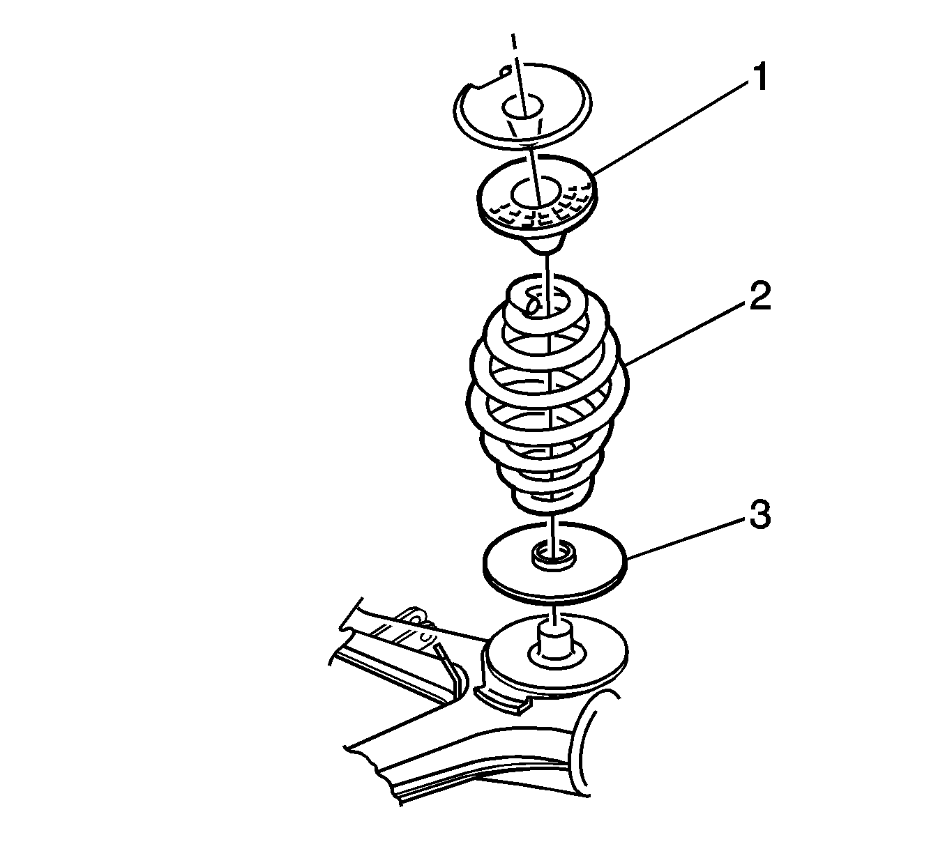
- Remove the spring and the 2 insulators from the control arm.
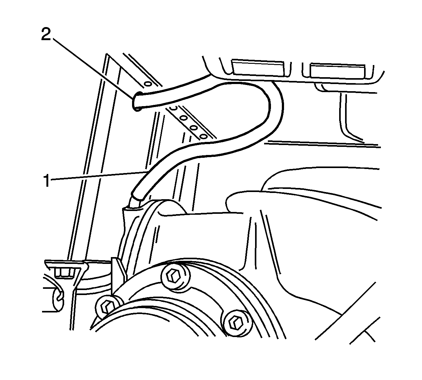
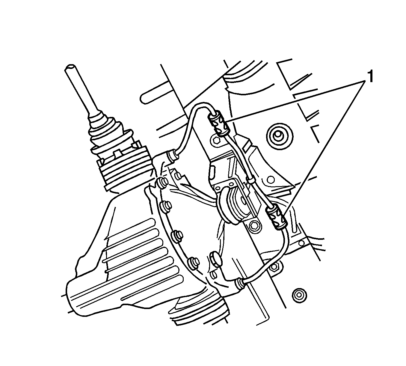
- Pull the differential carrier breather hose (1) out of the hole (2).
- Separate the 2 wheel speed sensor wires from the clips (1).
- Disconnect the wheel speed sensor connectors from the body harness.
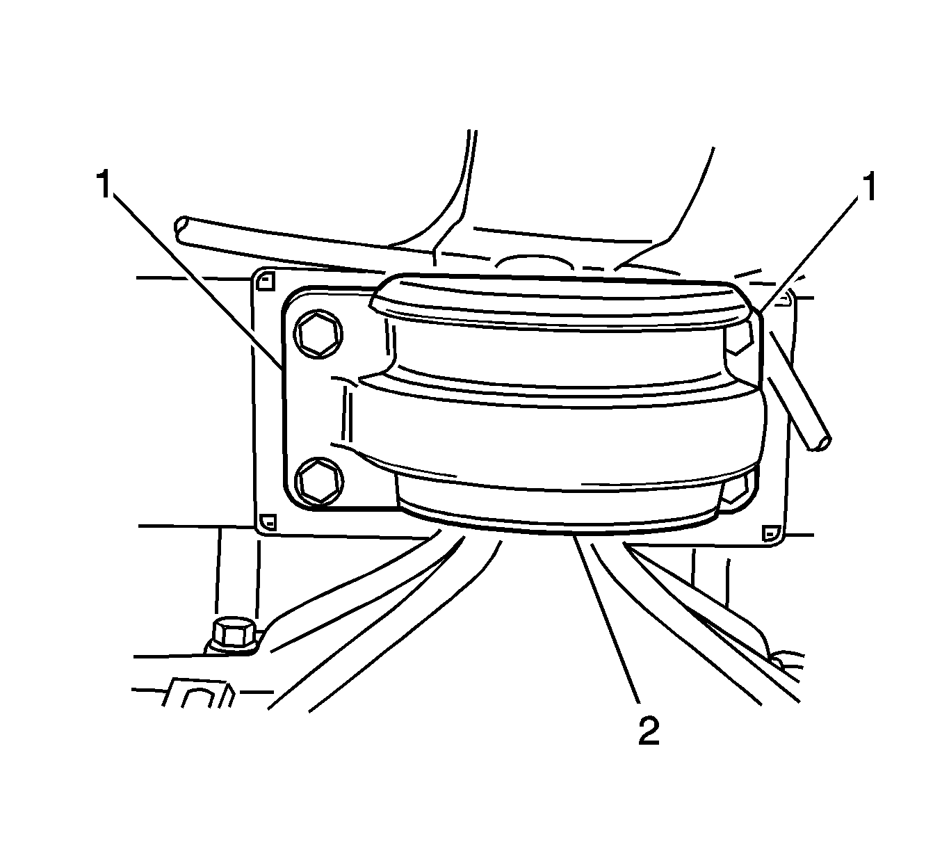
- Use paint or a scribe in order to mark the outline (1) of the differential carrier assembly mount (2) on the body.
- Use a jack in order to support the mount.
- Remove and discard the 4 bolts (2) that retain the mount (1) to the body.
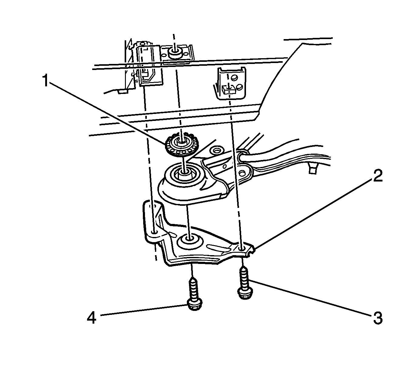
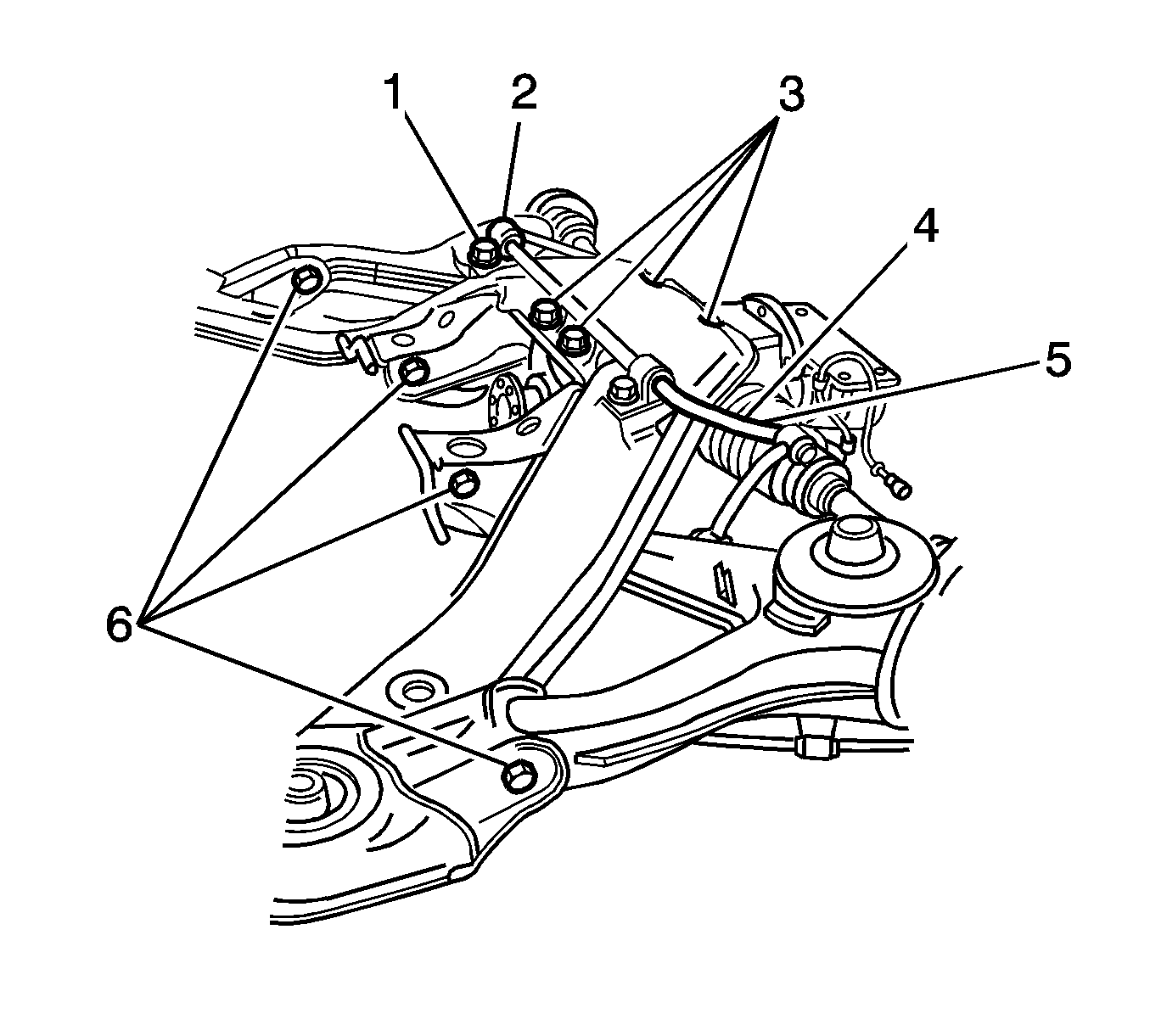
- Remove and discard the 2 bolts (4) that retain the rear suspension support to the body.
- Loosen the 6 brace bolts (3) as much as necessary in order to access the control arm fasteners.
- Lower the jack with the mount and the rear suspension support in order to access the control arm fasteners.
- Remove and discard the 2 nuts (6) that retain the control arm to the rear suspension support.
- Remove the 2 bolts and the control arm from the vehicle.
- If you are replacing the control arm, remove the following parts. Refer to Rear Wheel Bearing and Hub Replacement .
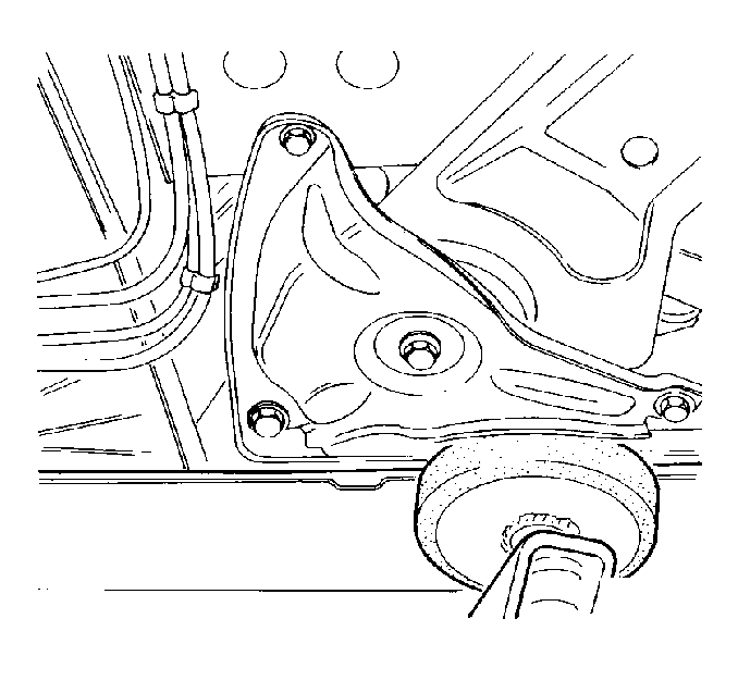
Important: Position the lift pads in order to minimize interference with the control arms and the rear suspension support.
Position the top of the nut with the top of the outer adjustment link stud.
Caution: Refer to Brake Fluid Irritant Caution in the Preface section.
Notice: Refer to Brake Fluid Effects on Paint and Electrical Components Notice in the Preface section.
Important: The brake rotor is indexed to the hub during production in order to minimize assembled lateral runout.
| 25.1. | Select a block of wood longer than the wheel studs. |
| 25.2. | Place the wood on the rotor between the wheel studs. |
| 25.3. | Tap the wood with a hammer in order to loosen the rotor from the hub. |
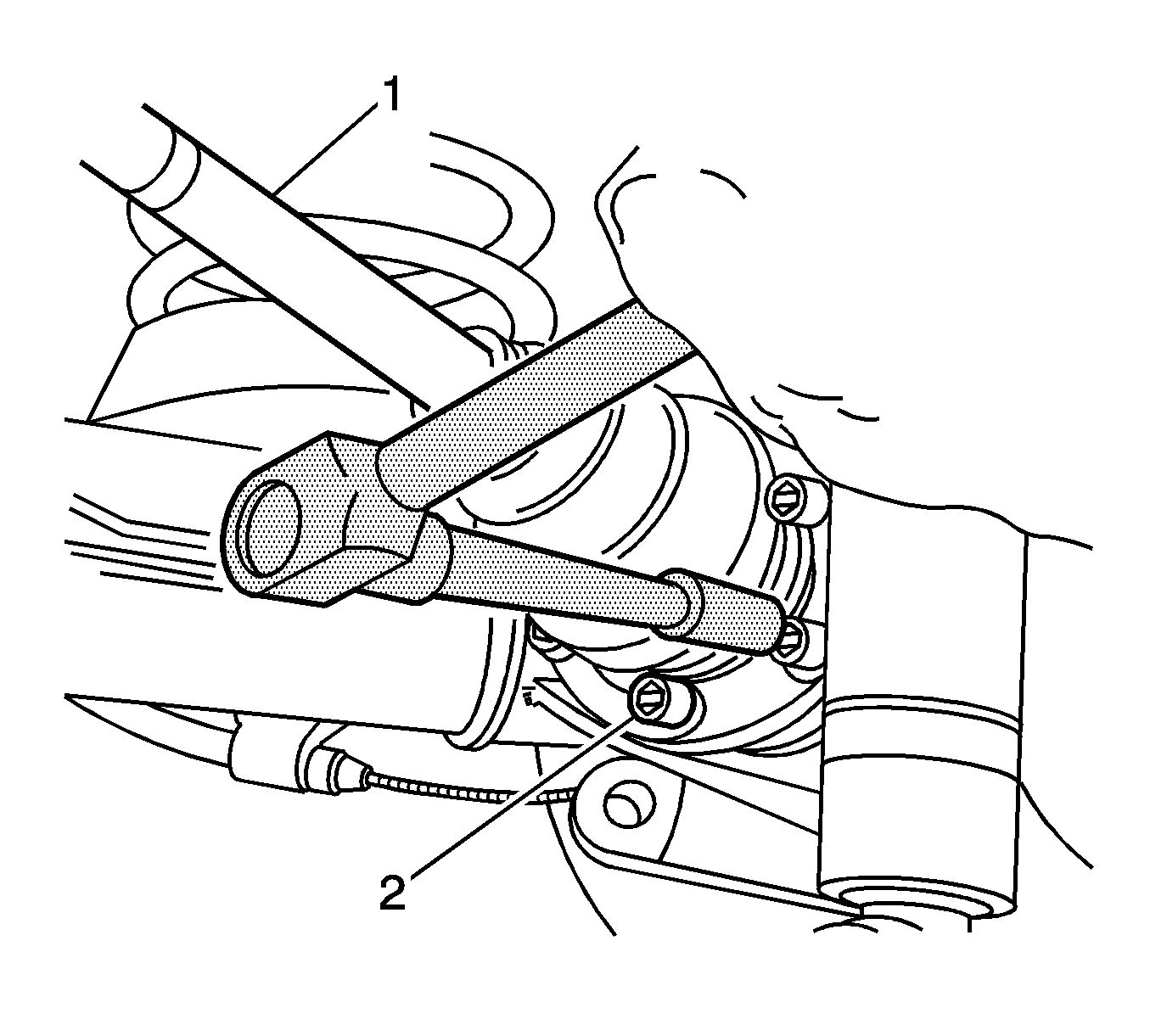
Important: DO NOT allow the wheel drive shaft to hang freely.
| • | The park brake components |
| • | The brake backing plate |
| • | The wheel bearing |
| • | The hub |
| • | The wheel drive shaft flange |
Installation Procedure
- If you replaced the control arm, install the following parts to the control arm. Refer to Rear Wheel Bearing and Hub Replacement .
- Install the control arm and the 2 bolts (6) to the rear suspension support.
- Install 2 NEW nuts in order to retain the control arm to the rear suspension support.
- Position a jack with a block of wood under the control arm.
- If you DID NOT replace the hub, use the J 42450-A in order to thoroughly clean any corrosion from the mating surface of the hub flange.
- If you DID NOT replace the brake rotor, use the J 41013 in order to thoroughly clean any corrosion from the mating surface of the rotor.
- Inspect the mating surfaces of the hub and the rotor. Verify that there are no foreign particles or debris remaining.
- Install the rotor to the hub. If you DID NOT replace the rotor, use the paint marks (1, 2, 3) for proper orientation of the rotor to the hub.
- If you installed the hub or the wheel drive shaft flange to the control arm, measure the assembled lateral runout of the rotor in order to ensure optimum performance of the disc brakes. Refer to Brake Rotor Assembled Lateral Runout Measurement in Disc Brakes.
- Position the caliper (2) and the bracket over the rotor.
- Install the 2 caliper bolts (1).
- Install the lower spring insulator (3) to the control arm.
- Install the spring (2) to the lower insulator.
- Install the upper spring insulator (1) to the spring.
- Raise the jack slightly in order to install the upper spring insulator to the body.
- Adjust the position of jack in order to align the control arm and the shock absorber.
- Install the washer and the bolt in order to retain the shock absorber to the control arm.
- Install the nut and the bolt in order to retain the stabilizer shaft link to the lower control arm.
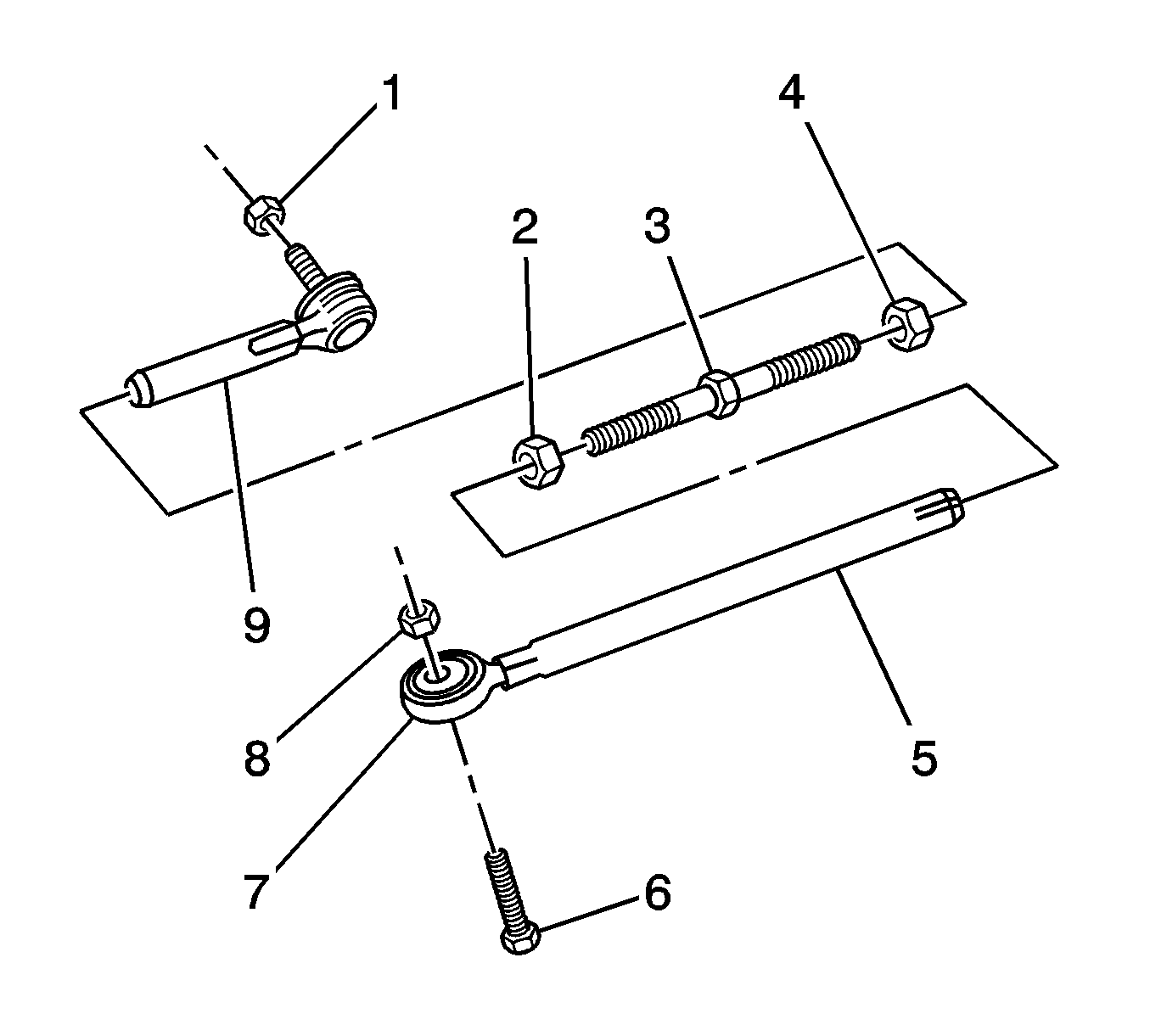
- Clean the stud on the outer adjustment link (9).
- Clean the hole in the control arm for the outer adjustment link stud.
- Install the outer adjustment link stud and a NEW nut (1) to the control arm.
- Remove the jack and the wood from the control arm.
- Install the J 42066 , or the equivalent tool, and 2 wheel nuts onto 2 studs in order to prevent the hub from turning.
- Install the retainers and the bolts (2) in order to retain the outer constant velocity joint to the drive shaft flange.
- Tighten the bolts to 50 N·m (37 lb ft).
- Use the J 45059 in order to tighten the bolts an additional 68 degrees.
- Remove the J 42066 , or the equivalent tool, and 2 wheel nuts from the 2 studs.
- Remove the wire supporting the wheel drive shaft.
- Raise the jack with the differential carrier assembly mount (1) and the rear suspension support.
- Align the mount with the match marks.
- Install 4 NEW bolts (2) in order to retain the mount to the body.
- Fit the CH-46839 to the underbody.
- With the aid of an assistant, position the rear suspension support.
- Install 2 NEW bolts in order to retain the rear suspension support to the body.
- Tighten the bolts to 125 N·m (92 lb ft).
- Use the J 45059 in order to tighten the bolts an additional 40 degrees.
- Tighten the 4 bolts that retain the differential mount to the body.
- Tighten the bolts to 35 N·m (26 lb ft).
- Use the J 45059 in order to tighten the bolts an additional 60 degrees.
- Tighten the 6 bolts that retain the 2 rear suspension support braces to the body.
- Remove the CH-46839 from the vehicle.
- Lower and remove the jack from under the vehicle.
- Install the differential carrier breather hose (1) into the hole (2).
- Reconnect the wheel speed sensor connectors and install the wires to the clips (1).
- Remove the caps or the plugs from the brake pipe (4) and the brake hose (1).
- Install the brake hose to the shield bracket (2).
- Install the clip (3) in order to retain the brake hose to the bracket.
- Install the brake pipe to the brake hose.
- Position the brake pipe and the brake hose (2) through the slot in the bracket (3) on the control arm.
- Install the clip (1) to the brake hose.
- If you removed the propeller shaft, install the propeller shaft. Refer to Two-Piece Propeller Shaft Replacement in Propeller Shaft.
- Install the rear park brake cable. Refer to Parking Brake Rear Cable Replacement - Left Side or to Parking Brake Rear Cable Replacement - Right Side in Park Brake.
- Install the 2 mufflers. Refer to Muffler Replacement in Engine Exhaust.
- Install the rear tire and wheel assemblies. Refer to Tire and Wheel Removal and Installation in Tires and Wheels.
- Bleed the brake system. Refer to Hydraulic Brake System Bleeding in Hydraulic Brakes.
- Lower the vehicle in order to place the weight of the vehicle on the tire and wheel assemblies.
- Bounce the rear of the vehicle several times in order to stabilize the suspension.
- Tighten the 2 nuts and the 2 bolts (6) that retain the control arm to the rear suspension support.
- Tighten the 2 nuts and the 2 bolts on the stabilizer shaft link.
- Tighten the bolt that retains the shock absorber to the control arm.
- Tighten the nut that retains the outer adjustment link to the control arm.
- Measure the wheel alignment. Adjust the alignment if necessary. Refer to Wheel Alignment Measurement in Wheel Alignment.
- Lower the vehicle from the alignment rack.
| • | The park brake components |
| • | The brake backing plate |
| • | The wheel bearing |
| • | The hub |
| • | The wheel drive shaft flange |

Important: Do not tighten the nuts or the bolts yet. The weight of the vehicle must be on the tire and wheel assemblies before tightening the nuts and the bolts.
Important: Corrosion and other contaminants from the hub and the rotor may result in excessive assembled lateral runout of the brake rotor, which could lead to brake pulsation.

Notice: Refer to Fastener Notice in the Preface section.
Tighten
Tighten the bolts to 85 N·m (63 lb ft).
Important: Do not tighten the bolt yet.
Important: Do not tighten the nut or the bolt yet.
Important: Do not tighten the nut yet.

Tighten

Important: Do not tighten the bolts yet.
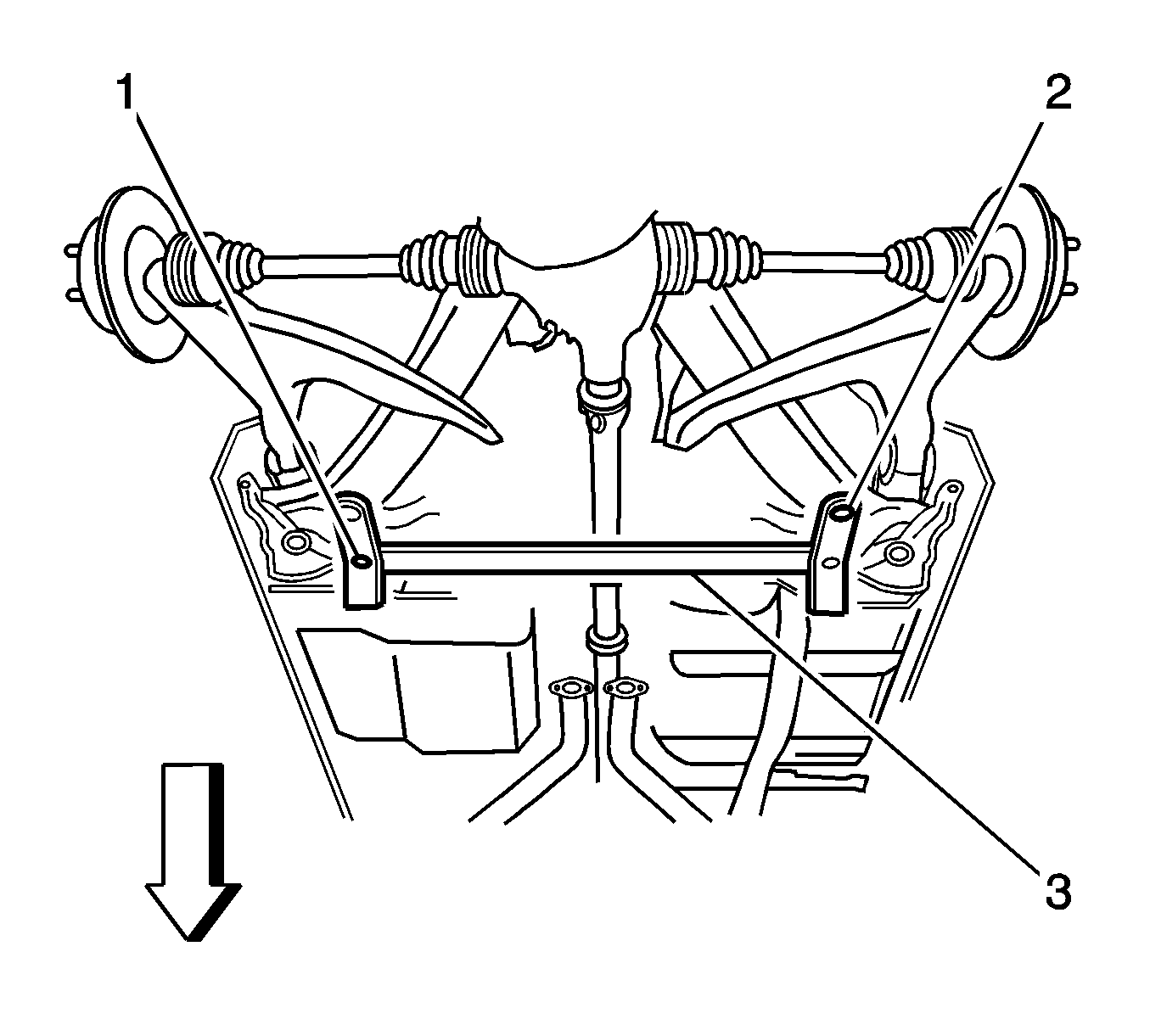
The CH-46839 locates into 19 mm (0.74 in) diameter body datum holes (1) positioned forward of the rear suspension support.
The locating pins (2) of the CH-46839 engage the alignment holes in the rear suspension support.
Tighten
Tighten
Tighten
Tighten the bolts to 70 N·m (52 lb ft).


Tighten
Tighten the fitting to 16 N·m (12 lb ft).


Tighten
Tighten the nuts and the bolts to 100 N·m (74 lb ft).
Tighten
Tighten the nuts and the bolts to 98 N·m (72 lb ft).
Tighten
Tighten the bolt to 115 N·m (85 lb ft).
Tighten
Tighten the nut to 63 N·m (46 lb ft).
