For 1990-2009 cars only
Removal Procedure
- Disable the SIR system. Refer to SIR Disabling and Enabling in SIR.
- Remove the key from the ignition switch.
- Remove the knee bolster assembly. Refer to Driver Knee Bolster Replacement in Instrument Panel, Gages, and Console.
- Remove the steering column trim covers. Refer to Steering Column Trim Covers Replacement .
- Tilt the column to the lowest position and telescope the column to the longest position.
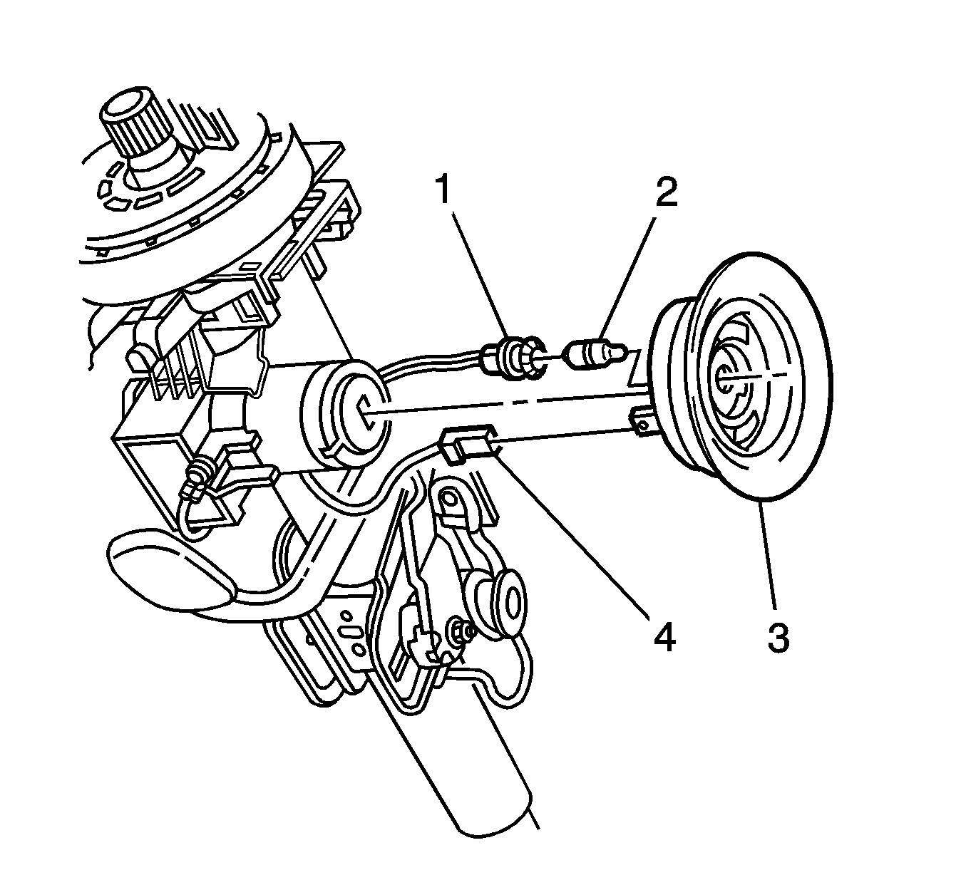
- Disconnect the connector (4) from the theft deterrent reader assembly (3).
- Remove the ignition lock illumination socket (1) and the bulb (2) from the reader assembly.
- Remove the reader assembly from the ignition lock cylinder.
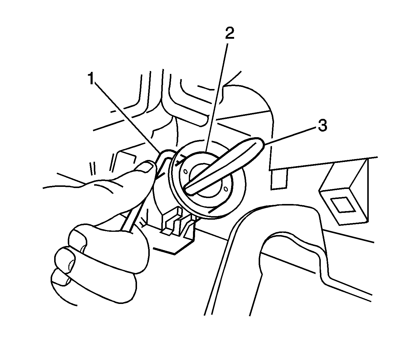
- Insert the key (3) into the ignition lock cylinder (2).
- Turn the key to the ON position.
- Ensure the steering column is NOT locked.
- Insert an Allen key, or an equivalent 2.5 mm (0.098 in) diameter drift, into the locking pin hole.
- Rotate the key slightly and remove the ignition lock cylinder from the housing.
Press the spring loaded barrel locking latch in order to release the ignition lock cylinder.
Installation Procedure
- Verify the steering column is not locked.
- Insert the key into the ignition lock cylinder.
- Turn the key to the ON position.
- Look through the ignition lock cylinder housing in order to inspect the keyed hole (2) in the ignition switch.
- Rotate the key slightly and align the keyed tip of the ignition lock cylinder with the keyed hole in the ignition switch.
- Install the cylinder to the housing.
- Remove the key from the ignition lock cylinder.
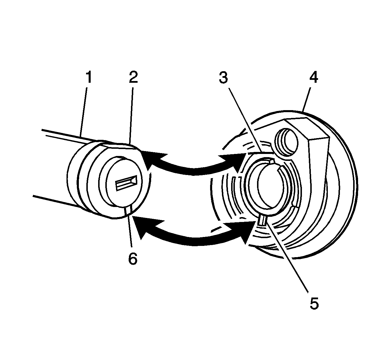
- Align the flat edge (3) on the theft deterrent reader assembly (4) with the flat edge (2) on the ignition lock cylinder (1).
- Align the indexing lug (5) on the reader assembly with the groove (6) on the ignition lock cylinder.
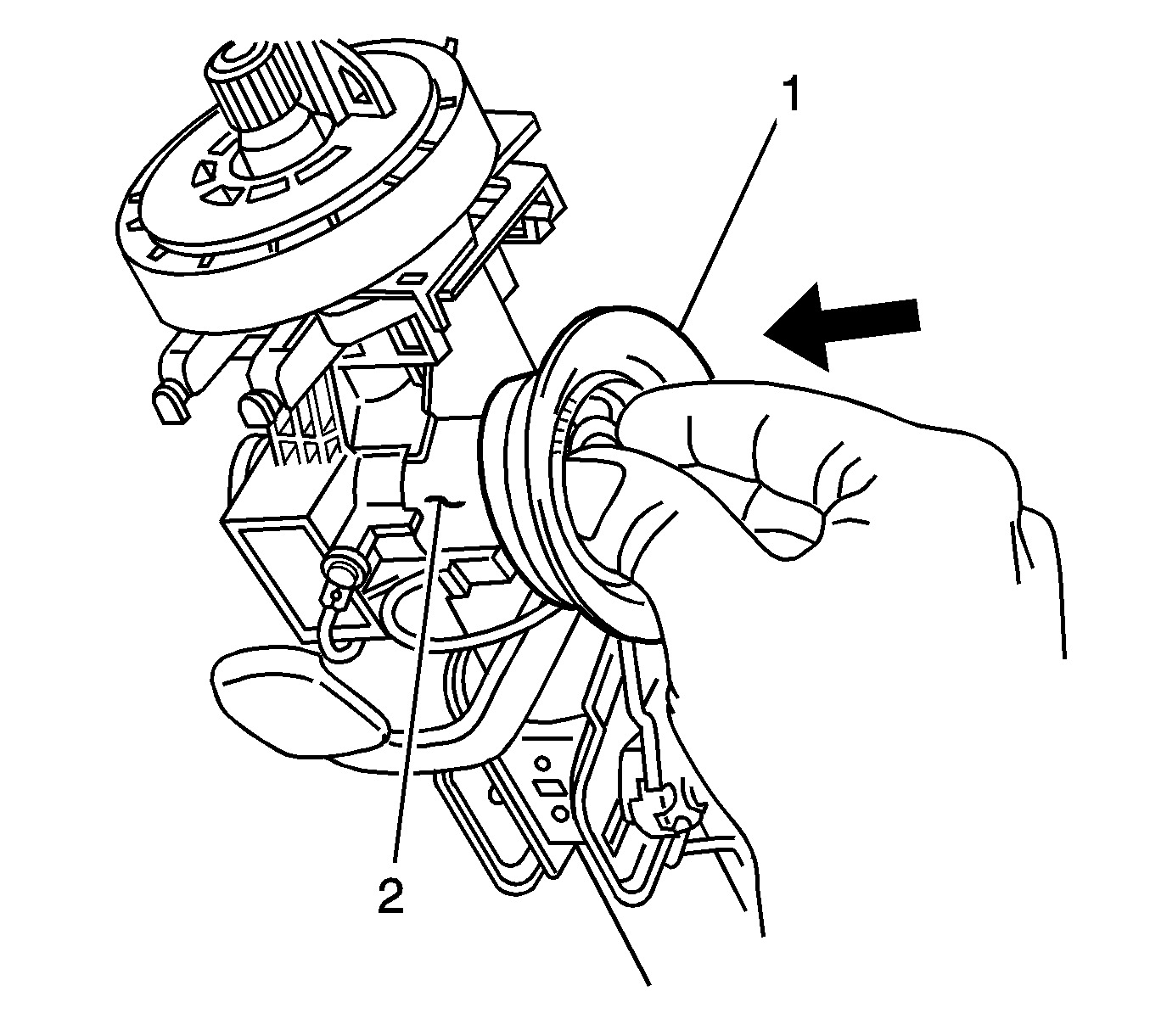
- Gently push on the reader assembly (1) between the flat edge and the indexing lug in order to install the reader assembly onto the ignition lock cylinder.
- Install the bulb and the illumination socket to the reader assembly.
- Connect the connector to the reader assembly.
- Install the steering column trim covers. Refer to Steering Column Trim Covers Replacement .
- Install the knee bolster assembly. Refer to Driver Knee Bolster Replacement in Instrument Panel, Gages, and Console.
- Enable the SIR system. Refer to SIR Disabling and Enabling in SIR.
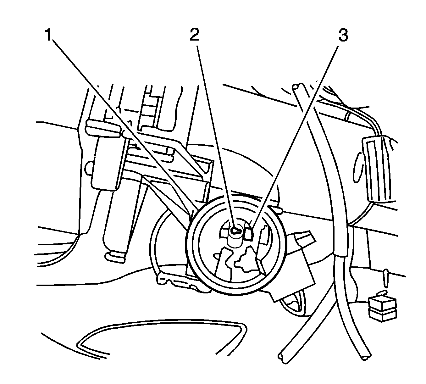
If the steering column is locked, complete the following steps:
| 1.1. | Inspect the inside of the ignition lock cylinder housing (1) on the steering column. |
| 1.2. | Locate the steering column lock tab (3) on the right side of the housing, toward the front of the vehicle. |
| 1.3. | Place a flat-bladed tool on the steering column lock tab. |
| 1.4. | Rotate the steering wheel slightly and push the steering column lock tab down. |
Ensure the latch locks into the housing.
Ensure the ignition lock cylinder spring moves the lock cylinder toward the right side of the vehicle.
