For 1990-2009 cars only
Tools Required
J 45059 Angle Meter
Removal Procedure
- Raise and support the vehicle. Refer to Lifting and Jacking the Vehicle .
- Remove the tire and wheel assembly. Refer to Tire and Wheel Removal and Installation .
- Remove the front brake rotor. Refer to Front Brake Rotor Replacement .
- If you are removing the left front hub, turn the steering wheel to the left.
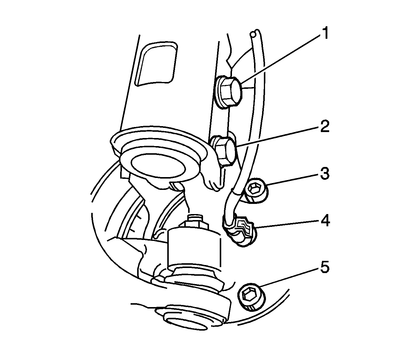
- Lift the locking tab on the wheel speed sensor connector (4).
- Disconnect the connector from the knuckle.
- If necessary in order to gain access, complete the following steps:
- Loosen the 3 Allen bolts (3,5) on the knuckle.
- If necessary, tap the 3 Allen bolts in order to loosen the hub from the knuckle.
- Remove the 3 Allen bolts and the hub from the knuckle.
If you are removing the right front hub, turn the steering wheel to the right.

| 7.1. | Remove and discard the 2 nuts that retain the strut to the knuckle. |
| 7.2. | If equipped, remove the 2 washers from the 2 bolts (1,2). |
| 7.3. | Remove and discard the 2 bolts. |
Important: Tap the Allen bolts. DO NOT strike the hub.
Installation Procedure
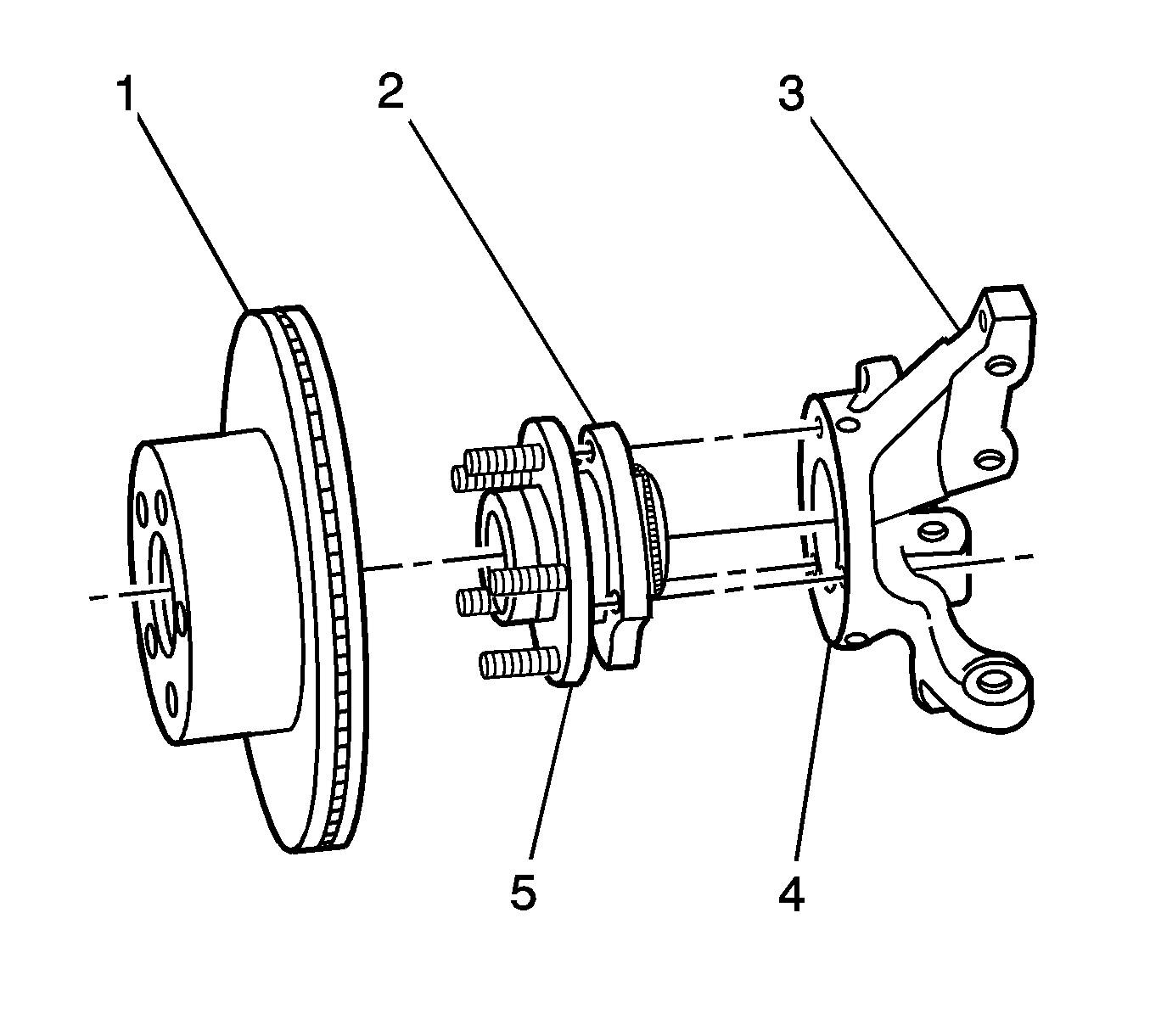
- Clean the mating surfaces of the knuckle (4).
- Clean the mating surfaces of the hub (2,5).
- Align the sensor connection on the hub with the hole in the knuckle.
- Install the hub to the knuckle.
- Install the 3 Allen bolts (3,5).
- Connect the wheel speed sensor connector (4).
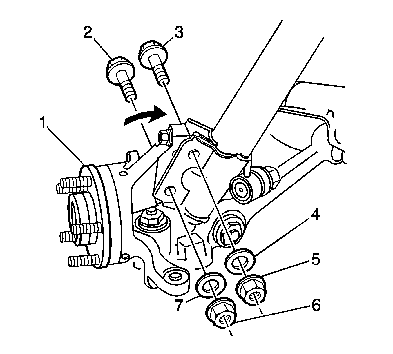
- If you separated the knuckle from the strut, install the 2 NEW bolts (2,3), the 2 washers (4,7), and the 2 NEW nuts (5,6).
- Tighten the nuts to 85 N·m (63 lb ft).
- Tighten the nuts to 100 N·m (74 lb ft).
- Use the J 45059 in order to tighten the nuts an additional 90 degrees.
- Install the front brake rotor. Refer to Front Brake Rotor Replacement .
- If you replaced the hub, measure the assembled lateral runout (LRO) of the brake rotor in order to ensure optimum performance of the disc brakes. Refer to Brake Rotor Assembled Lateral Runout Measurement .
- If the brake rotor assembled LRO measurement exceeds the specification, adjust the LRO to the specification. Refer to Brake Rotor Assembled Lateral Runout Correction .
- Install the tire and wheel assembly. Refer to Tire and Wheel Removal and Installation .
- Lower the vehicle.

Verify the mating surfaces are free from burrs.
Verify the mating surfaces are free from burrs.
Notice: Refer to Fastener Notice in the Preface section.

Important: The Allen bolts that retain the hub to the knuckle have thread sealant. Do not re-use the bolts more than 3 times. If in doubt, replace the 3 Allen bolts.
Tighten
Tighten the bolts to 108 N·m (80 lb ft).
Ensure the locking tab on the connector is secure.

Tighten
