For 1990-2009 cars only
Removal Procedure
- Disconnect the negative battery cable. Refer to Battery Negative Cable Disconnection and Connection .
- Remove the left closeout panel. Refer to Instrument Panel Insulator Panel Replacement - Left Side .
- Remove the left ventilation ducts. Refer to Instrument Panel Air Outlet Ducts Replacement .
- If the vehicle has a manual transmission, remove the clutch pedal bracket assembly. Refer to Clutch Pedal Replacement .
- Remove the cruise control release switch. Refer to Cruise Control Release Switch Replacement .
- Remove the stop lamp switch. Refer to Stop Lamp Switch Replacement .
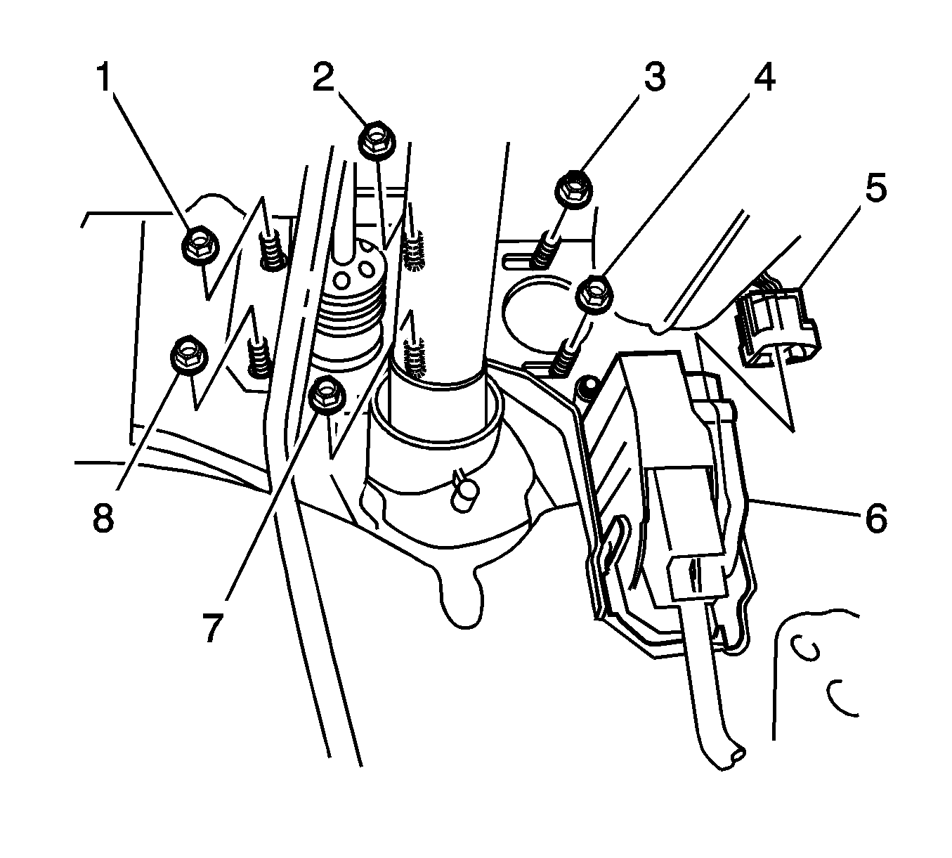
- Disconnect the accelerator pedal harness connector (5) from the accelerator pedal sensor (6).
- Remove the brake master cylinder assembly. Refer to Master Cylinder Replacement .
- Remove the vacuum brake booster. Refer to Power Vacuum Brake Booster Replacement .
- Remove the 2 nuts (3,4) from the brake pedal bracket.
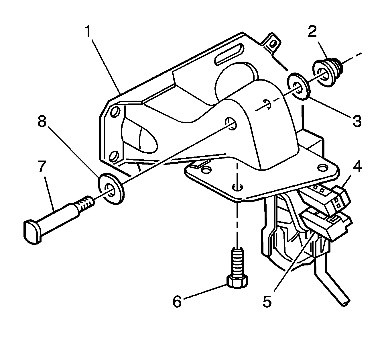
- Remove the 3 bolts (6) from the brake pedal bracket (1).
- Lower the rearward side of the brake pedal assembly.
- Remove the brake pedal assembly from the vehicle.
- Remove the nut (2) and the washer (3) from the brake pedal shaft (7).
- Remove the brake pedal shaft and the washer (8) from the brake pedal bracket.
- Remove the brake pedal with the return spring.
- Remove the return spring.
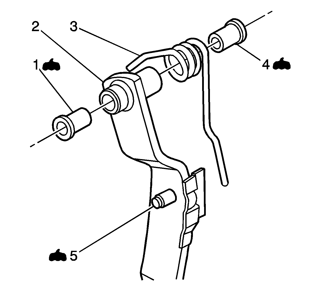
- Remove the brake pedal pivot bushings.


Installation Procedure
- Apply GM Vehicle Care® Dri-Slide Lubricant, GM P/N 1052948, or the equivalent NLGI No. 2 lithium soap based EP lubricant with molybdenum disulphide, to the brake pedal pivot bushings (1, 4) and to the push rod pivot point (5).
- Install the brake pedal pivot bushings to the brake pedal.
- Hold the brake pedal and the return spring in position and install the brake pedal shaft (7) and the washer (8) to the brake pedal bracket (1).
- Install the washer (3) and the nut (2) to the brake pedal shaft.
- Position the brake pedal assembly in the vehicle.
- Install the 3 bolts (6) in order to retain the brake pedal bracket.
- Install the vacuum brake booster. Install the booster push rod to the brake pedal. Refer to Power Vacuum Brake Booster Replacement .
- If the vehicle has a manual transmission, install the clutch pedal bracket assembly. Refer to Clutch Pedal Replacement .
- Install the 2 nuts (3,4) to the brake pedal bracket.
- Install the accelerator pedal connector (5) to the accelerator pedal sensor (6).
- Install the stop lamp switch. Refer to Stop Lamp Switch Replacement .
- Install the cruise control release switch. Refer to Cruise Control Release Switch Replacement .
- Tighten the 3 bolts that retain the brake pedal bracket.
- Install the brake master cylinder assembly and bleed the brake system. Refer to Master Cylinder Replacement .
- Install the left ventilation ducts. Refer to Instrument Panel Air Outlet Ducts Replacement .
- Install the left I/P lower insulator panel. Refer to Instrument Panel Insulator Panel Replacement - Left Side .
- Connect the negative battery cable. Refer to Battery Negative Cable Disconnection and Connection .


Notice: Refer to Fastener Notice in the Preface section.
Tighten
Tighten the nut to 55 N·m (41 lb ft).
Important: Do not tighten the bolts yet.
Important: Do not install the brake master cylinder yet.

Tighten
Tighten the nuts to 25 N·m (18 lb ft).
Tighten
Tighten the bolts to 25 N·m (18 lb ft).
