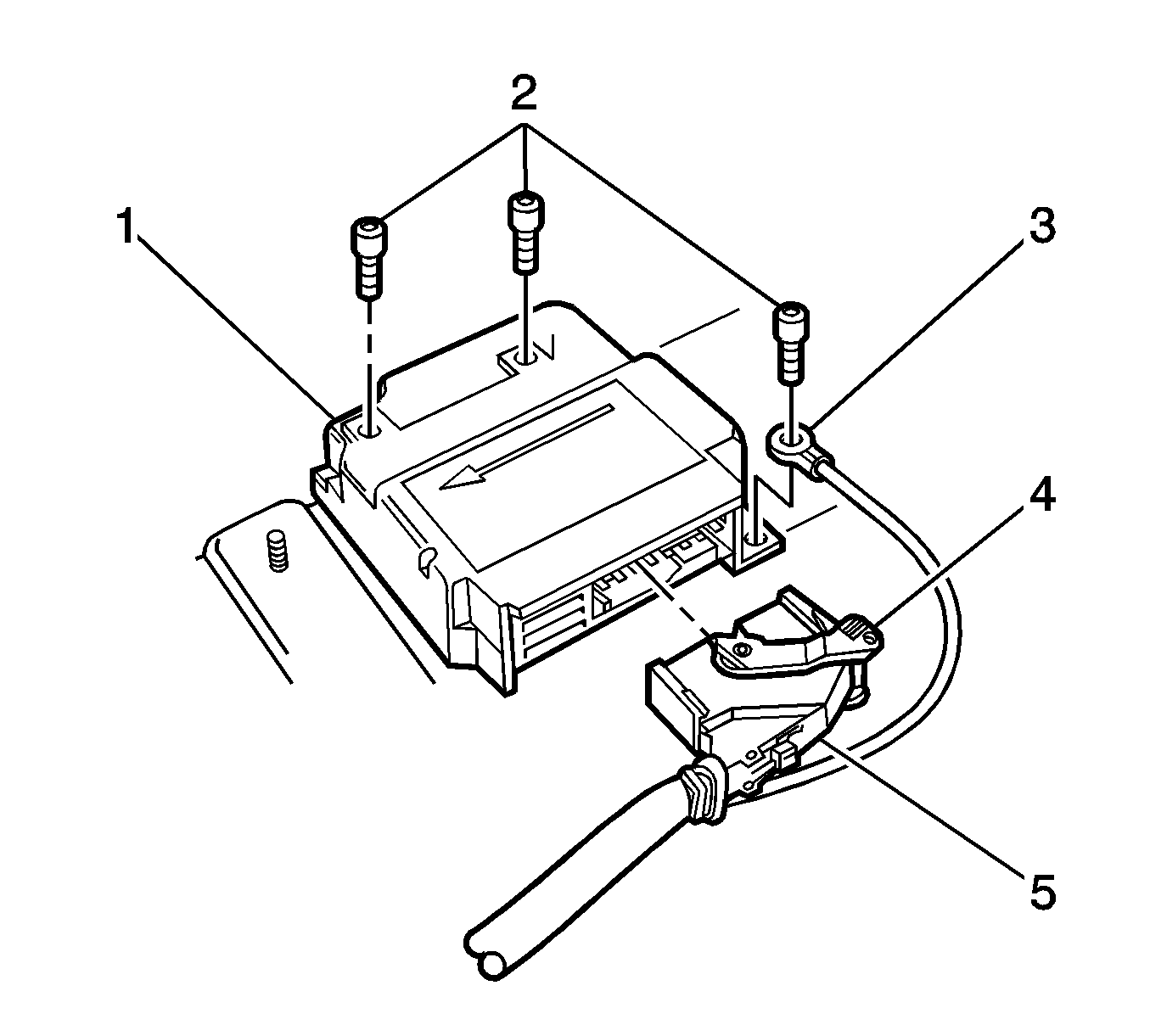
Removal Procedure
- Disable the SIR system. Refer to SIR Disabling and Enabling .
- Remove the console in order to access the sensing and diagnostic module (SDM) (1). Refer to Front Floor Console Replacement in Instrument Panel, Gages and Console.
- Remove the SDM electrical connector. Press the locking tab (5) and move the locking lever (4) rearward while removing the connector from the SDM (1).
- Remove the three SDM fasteners (2).
- Remove the SDM assembly (1) from the vehicle.
Caution: Do not strike or jolt the inflatable restraint sensing and diagnostic module (SDM). Before applying power to the SDM, make sure that it is securely fastened with the arrow facing toward the front of the vehicle. Failure to observe the correct installation procedure could cause SIR deployment, personal injury, or unnecessary SIR system repairs.
Caution: If the vehicle interior is exposed to moisture and becomes soaked up to the level of the sensing and diagnostic module (SDM), the SDM and SDM harness connector must be replaced. The SDM could be activated when powered, which could cause airbag deployment and result in personal injury.

Installation Procedure
- Install the SDM assembly (1) into the vehicle. Ensure arrow on SDM label is pointing towards the front of the vehicle.
- Install the three SDM fasteners (2).
- Install the SDM electrical connector.
- Install the center console. Refer to Front Floor Console Replacement in Instrument Panel, Gages and Console.
- Enable the SIR system. Refer to SIR Disabling and Enabling .

Notice: Use the correct fastener in the correct location. Replacement fasteners must be the correct part number for that application. Fasteners requiring replacement or fasteners requiring the use of thread locking compound or sealant are identified in the service procedure. Do not use paints, lubricants, or corrosion inhibitors on fasteners or fastener joint surfaces unless specified. These coatings affect fastener torque and joint clamping force and may damage the fastener. Use the correct tightening sequence and specifications when installing fasteners in order to avoid damage to parts and systems.
Important: Ensure the wiring harness ground lead (3) is installed under the left rear SDM (1) retaining bolt.
Tighten
Tighten the fasteners to 9 N·m (80 lb in).
