For 1990-2009 cars only
Removal Procedure
- Disable the SIR system. Refer to SIR Disabling and Enabling.
- Remove the glove box. Refer to Instrument Panel Storage Compartment Replacement.
- Remove the center instrument panel bezel. Refer to Instrument Panel Outer Trim Cover Replacement.
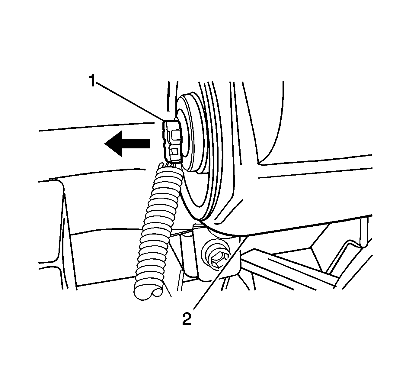
- Disconnect the I/P module connector (1).
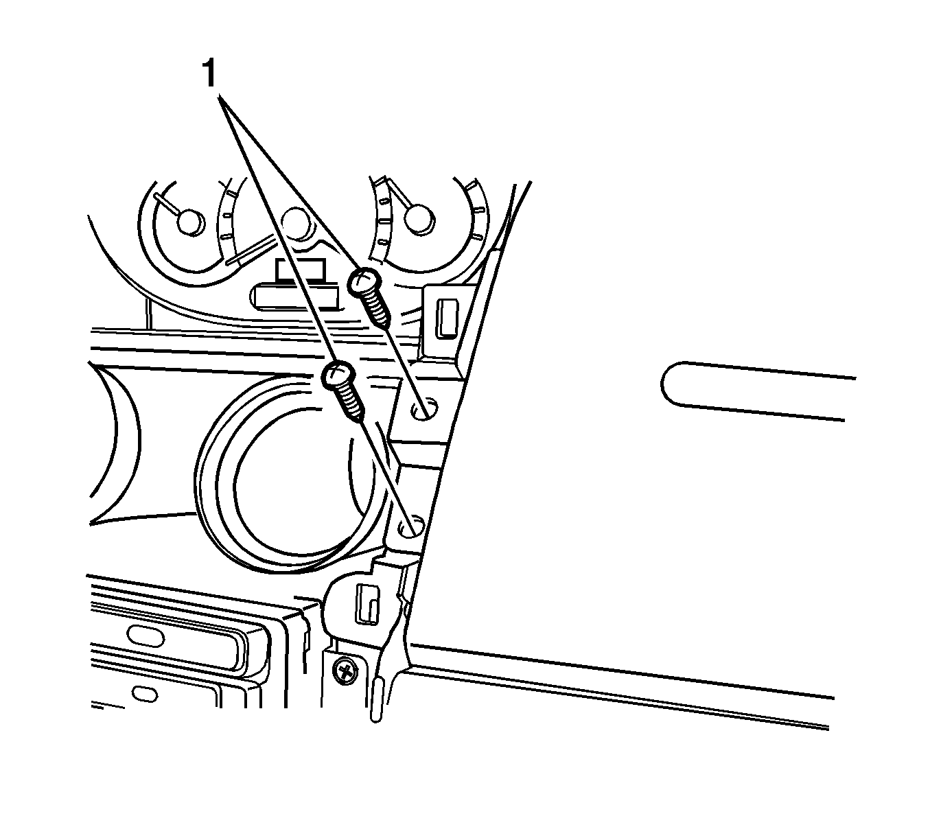
- Remove the 2 I/P module fasteners (1).
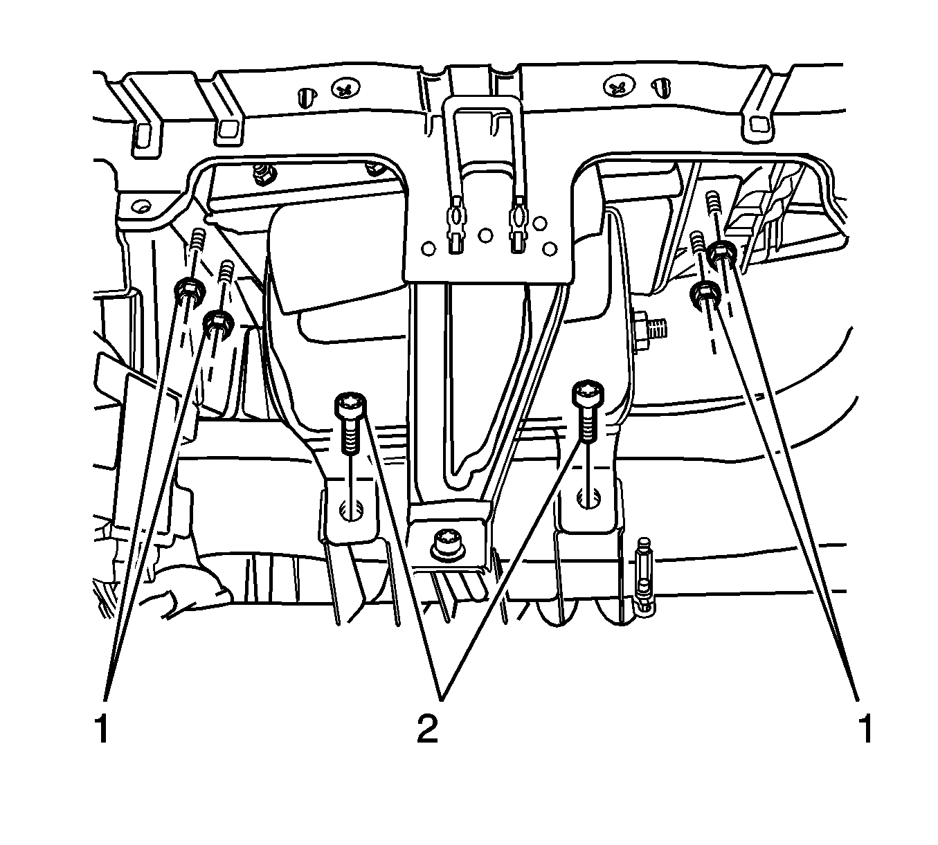
- Remove the 4 I/P module fasteners (1).
- Remove the 2 I/P module fasteners (2).
- Remove the I/P module.
Warning: Refer to Sensing and Diagnostic Module Voltage after Ignition is Turned Off Warning in the Preface section.
Warning: Refer to Battery Disconnect Warning in the Preface section.
Installation Procedure
- Install the I/P module.
- Install the 2 I/P module fasteners (2) and tighten to 12 N·m (106 lb in).
- Install the 4 I/P module fasteners (1) and tighten to 10 N·m (89 lb in).
- Install the 2 I/P module fasteners (1).
- Connect the I/P module connector (1).
- Install the center instrument panel bezel. Refer to Instrument Panel Outer Trim Cover Replacement.
- Install the glove box. Refer to Instrument Panel Storage Compartment Replacement.
- Enable the SIR system. Refer to SIR Disabling and Enabling.
Caution: Refer to Fastener Caution in the Preface section.
