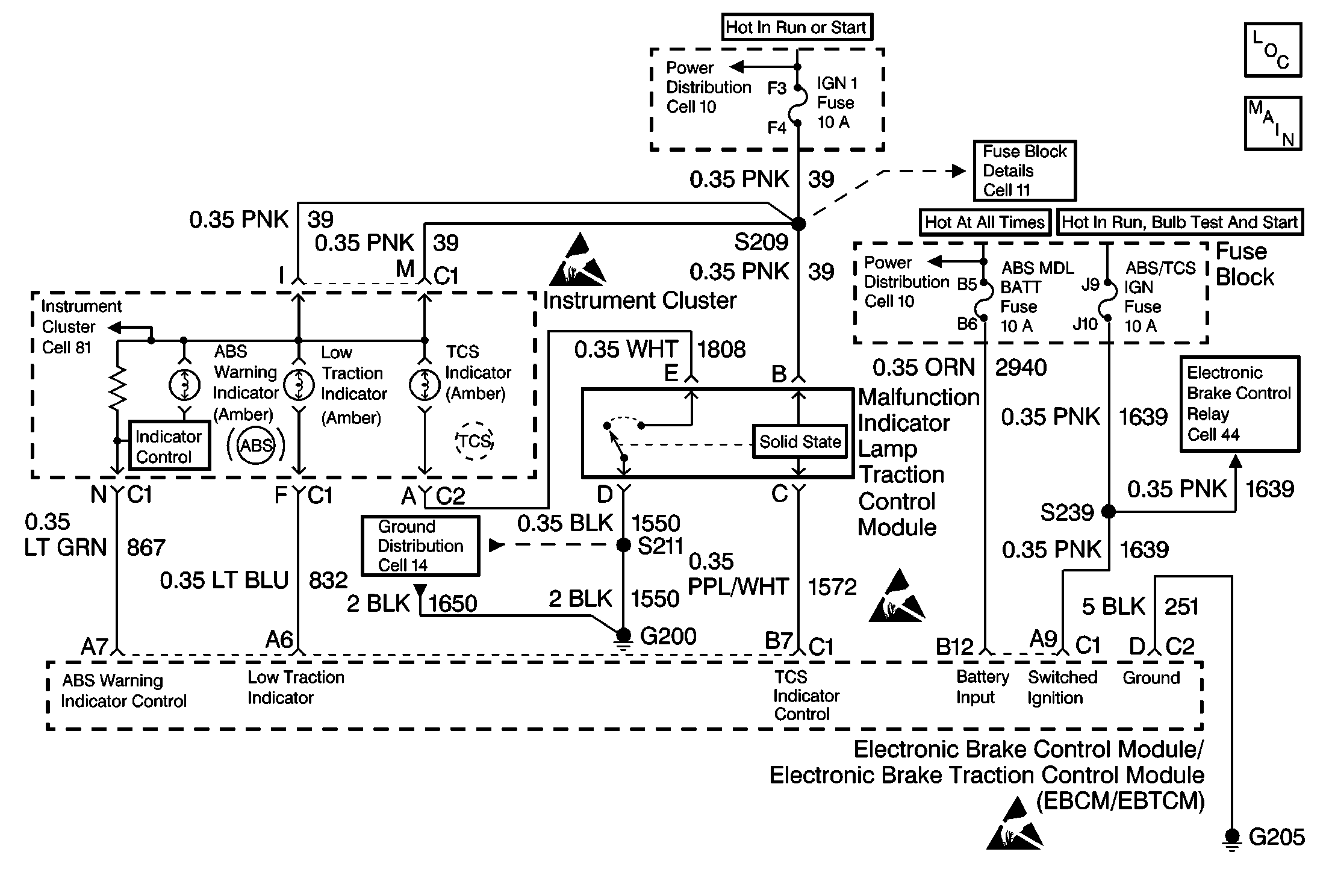
Circuit Description
This symptom table tests the state of the TCS warning indicator in order to identify either of the following conditions:
| • | The TCS warning indicator could not warn the driver of a system malfunction |
| • | The TCS warning indicator is always on |
The EBCM/EBTCM must provide a ground in order to turn the amber TCS warning indicator off because of Malfunction Indicator Lamp Control Module (lamp driver module) in the circuit. Because of the circuitry in the integral Lamp Driver Module (LDM), only external malfunctions can be detected. As a result, the integral LDM is not diagnosable. If CKT 1572 is open, the TCS warning indicator will remain on due to the loss of ground at the integral LDM input. If the control line is shorted to ground, the TCS warning indicator will remain off. The TCS warning indicator will remain off because the integral LDM input will be grounded. DTC C1311 will set if any of the following conditions exist:
| • | An open in CKT 1572 |
| • | A short to ground on CKT 1572 |
| • | A short to voltage in CKT 1572 |
Diagnostic Aids
Use the Lamp Test function of the Scan Tool in order to turn the indicator on while looking for an intermittent malfunction in the TCS warning indicator circuitry.
Thoroughly inspect any circuitry that may cause the intermittent complaint for the following conditions:
| • | Rubbed-through wire insulation |
| • | A broken wire inside the insulation |
| • | Backed out terminals |
| • | Improper mating |
| • | Broken locks |
| • | Improperly formed or damaged terminals |
| • | Poor terminal-to-wiring connections |
| • | Physical damage to the wiring harness |
Important: Zero the J 39200 test leads before making any resistance measurements.
Step | Action | Value(s) | Yes | No | ||||||||||||
|---|---|---|---|---|---|---|---|---|---|---|---|---|---|---|---|---|
1 | Was the Diagnostic System Check performed? | -- | ||||||||||||||
2 |
Is the TCS indicator off? | -- | ||||||||||||||
3 |
Are there signs of poor terminal contact, corrosion, or terminal corrosion? | -- | ||||||||||||||
4 |
Is the TCS indicator off? | -- | ||||||||||||||
5 |
Is the voltage measured greater than the specified voltage? | 10 V | ||||||||||||||
6 | Replace all of the terminals or the connectors that exhibit signs of the following conditions:
Is the repair complete? | -- | -- | |||||||||||||
7 | Repair the open in CKT 39. Is the repair complete? | -- | -- | |||||||||||||
8 | Repair the short to ground in CKT 1808. Is the repair complete? | -- | -- | |||||||||||||
9 | Replace the Malfunction Indicator Lamp Traction Control Module. Refer to Lamp Driver Module Replacement . Is the repair complete? | -- | -- | |||||||||||||
10 | Replace the EBCM/EBTCM. Refer to Electronic Brake and Traction Control Module Replacement . Is the repair complete? | -- | -- |
