Special Tools
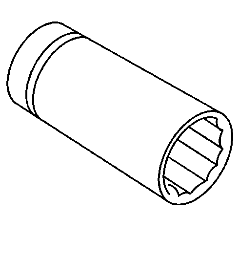
| • | J 34826 Hub Nut Socket (36 mm) |
| • | J 45005 Seal Installer |
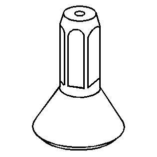
| • | J 45012 Holding Fixture |
| • | J 45019 Flange and Pinion Cage Remover |
Removal Procedure
- Raise and support vehicle. Refer to Lifting and Jacking the Vehicle .
- Remove the floor panel tunnel rear panel. Refer to Floor Panel Tunnel Panel Replacement - Rear .
- Support the rear drive module (RDM).
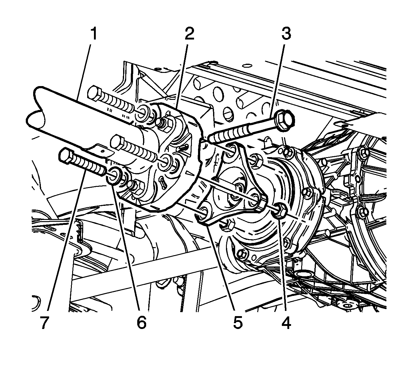
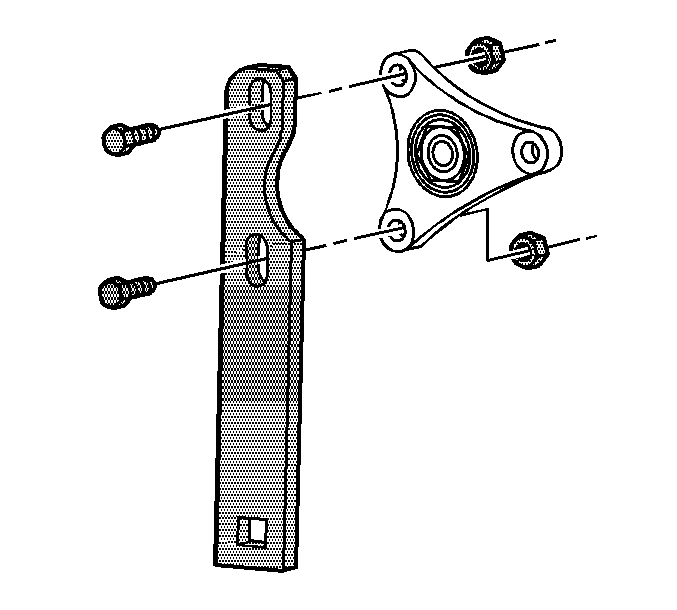
- Remove the differential carrier bracket-to-frame bolt (3).
- Remove the propeller shaft coupler-to-differential flange nuts (4), bolts (7), and washers (6).
- Push the propeller shaft (1) toward the front of the vehicle in order to release the propeller shaft coupler (2) from the differential pinion flange (5).
- Lower the propeller shaft and the front of the RDM until disconnected.
- Carefully position the propeller shaft (1) aside and support the propeller shaft using a suitable jack.
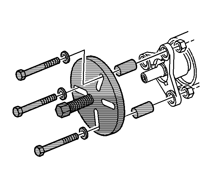
- Install the J 45012 to the flange.
- While holding the J 45012 , remove the drive pinion nut using J 34826 .
- Remove the J 45012 .
- Install the J 45019 to the flange.
- Using the J 45019 , remove the flange.
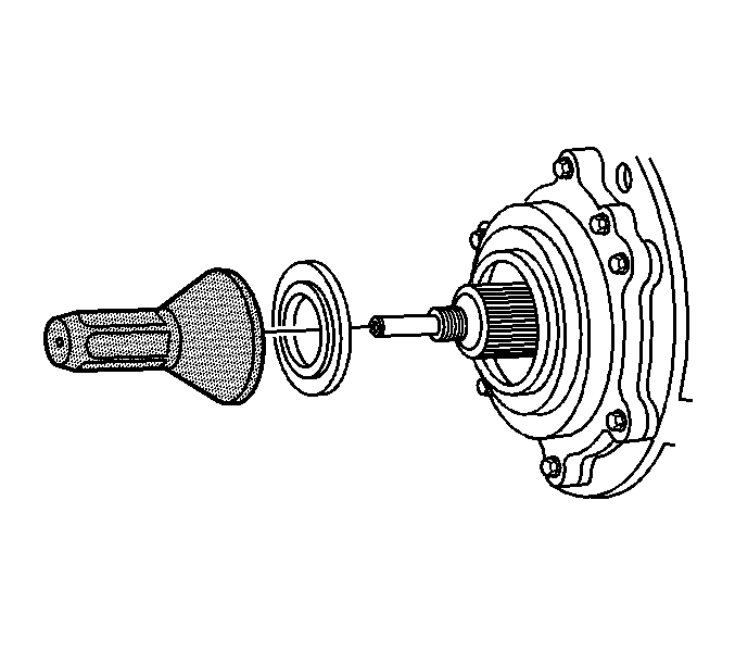
- Using a flat-bladed tool, remove the drive pinion seal. Take care not to damage any sealing surfaces.
Important: Remove only the propeller shaft coupler-to-differential flange bolts. Do NOT remove the coupler from the propeller shaft.
Installation Procedure
- Lubricate the drive pinion flange sealing surface of the drive pinion seal with synthetic gear oil GM P/N 12378514 (Canadian P/N 88901045) or equivalent.
- Install the drive pinion seal to the J 45005 .
- Using the J 45005 , install the pinion seal to the differential.
- Remove the J 45005 .
- Remove the J 45019 .
- Install the J 45012 .
- Install the pinion flange to the drive pinion shaft.
- Prepare the pinion shaft threads and the pinion flange nut for assembly:
- Apply threadlocker GM P/N 12345382 (Canadian P/N 10953489) or equivalent to 2/3 of the threaded length of the pinion shaft threads. Ensure that there are no gaps in the threadlocker along the length of the filled area of the pinion shaft threads.
- Allow the threadlocker to cure approximately 10 minutes before installation.
- Install the drive pinion flange nut to the pinion shaft. While holding the J 45012 , use J 34826 to tighten the drive pinion nut.
- Remove the J 45012 .
- Raise the propeller shaft and the front of the RDM until the propeller shaft is installed to the pinion flange.
- Install the propeller shaft coupler (2) to the differential flange (5).
- Remove the support.
- Inspect the propeller shaft to flange nuts (4), bolts (7), and washers (6). Replace if damaged or worn.
- Thoroughly clean the threads using denatured alcohol or equivalent and allow to dry. Apply threadlocker GM P/N 12345493 (Canadian P/N 10953488) or equivalent to the propeller shaft to the flange bolt. Ensure that there are no gaps in the threadlocker along the length of the filled area of the bolt. Allow the threadlocker to cure approximately 10 minutes before installation.
- Install the propeller shaft coupler-to-differential flange washers (4) to the propeller shaft coupler-to-differential flange bolts (3).
- Install the propeller shaft coupler-to-differential flange bolts and washers to the differential flange and propeller shaft coupler.
- Install the propeller shaft coupler-to-differential flange nuts.
- Install the bolt from the differential case bracket assembly to body.
- Remove the RDM support.
- Install the floor panel tunnel rear panel. Refer to Floor Panel Tunnel Panel Replacement - Rear .
- Inspect the fluid level. Refer to Rear Axle Lubricant Level Inspection .
- Lower the vehicle.
Important: Ensure the pinion bore is free of excess gear oil. Excessive fluid can get trapped behind the new seal's dust shield. The trapped gear oil can get squeezed out when installing the pinion flange and give the illusion of a continued leak.
Important: The pinion shaft threads and the pinion flange nut must be free of residue and debris prior to application of threadlocker in order to ensure proper adhesion and fastener retention.
| 8.1. | Thoroughly clean the residue from the pinion shaft threads by using denatured alcohol or equivalent and allow to dry. |
| 8.2. | Thoroughly clean the residue from the pinion flange nut by using denatured alcohol or equivalent and allow to dry. |
Notice: Refer to Fastener Notice in the Preface section.
Tighten
Tighten the pinion flange nut to 245 N·m (181 lb ft).
Important: If reusing the propeller shaft to flange nuts and bolts, to ensure proper adhesion and fastener retention, the threads must be free of debris prior to the application of threadlocker.
Tighten
Tighten the propeller shaft coupler-to-differential flange bolts to 85 N·m (63 lb ft).
Special Tools
| • | J 34826 Hub Nut Socket (36 mm) |
| • | J 42851 Front Cover oil Seal Installer |
| • | J 45012 Holding Fixture |
| • | J 45019 Flange and Pinion Cage Remover |
Removal Procedure
- Raise and support the vehicle. Refer to Lifting and Jacking the Vehicle.
- Remove the floor panel tunnel rear panel. Refer to Floor Panel Tunnel Panel Replacement - Rear.
- Remove the propeller shaft, differential and driveline support. Refer to Propeller Shaft, Differential, and Driveline Support Replacement.
- Remove the propeller shaft from the rear differential. Refer to Propeller Shaft Replacement.
- Carefully position the propeller shaft to the side and support using a suitable jack stand.
- Remove the differential carrier bracket. Refer to Differential Carrier Bracket Replacement
- Install the J 45012 to the flange.
- While holding the J 45012 , remove the drive pinion nut using the J 34826 .
- Remove the J 45012 from the flange.
- Install the J 45019 to the flange.
- Using the J 45019 , remove the flange.
- Using a flat-bladed tool, remove the drive pinion seal. care not to damage any of the sealing surfaces.
Important: The following service procedure is for those vehicles equipped with a manual transmission and drive line support. For vehicles equipped with a automatic transmission, proceed to Step 4.
Important: Remove only the propeller shaft coupler to differential flange bolts. DO NOT remove the coupler from the propeller shaft.
Installation Procedure
- Lubricate the drive pinion flange sealing surface of the drive pinion seal with synthetic gear oil GM P/N 121378514 (Canadian P/N 88901045) or equivalent.
- Using the J 42851 , install the drive pinion seal in the differential.
- Remove the J 45019 .
- Install the J 45012 .
- Install the pinion flange to the drive pinion shaft.
- Clean all the residue from the pinion shaft threads by using denatured alcohol or equivalent and allow to dry.
- Clean all the residue from the pinion flange nut by using denatured alcohol or equivalent and allow to dry
- Apply the threadlocker GM P/N 12345382 (Canadian P/N 10953489) or equivalent to 2/3 of the threads length of the pinion shaft threads.
- Allow the threadlocker to cure approximately 10 minutes before installation.
- Install the drive pinion flange nut to the pinion shaft. While holding the J 45012 , use the J 34826 to tighten the drive pinion nut.
- Remove the J 45012 .
- Install the differential carrier bracket. Refer to Differential Carrier Bracket Replacement
- Install the propeller shaft, differential and driveline support. Refer to Propeller Shaft, Differential, and Driveline Support Replacement.
- Install the propeller shaft to the differential. Refer to Propeller Shaft Replacement.
- Install the floor panel tunnel rear panel. Refer to Floor Panel Tunnel Panel Replacement - Rear.
- Inspect the fluid level Refer to Rear Axle Lubricant Level Inspection.
- Remove the support and lower the vehicle.
Important: Ensure that the pinion bore is free of excess gear oil. Excessive fluid can get trapped behind the new seal's dust shield. The trapped gear oil can get squeezed out when installing the pinion flange and appear the pinion seal still leaks.
Important: The pinion shaft threads and pinion flange nut must be free of residue and debris prior to application of the threadlocker order to ensure proper adhesion and fastener retention.
Important: Ensure that there are no gaps in the threadlocker along the length of the filled area of the pinion shaft threads.
Notice: Refer to Fastener Notice in the Preface section.
Tighten
Tighten the pinion flange nut to 245 N·m (181 lb ft).
Important: The following service procedure is for those vehicles equipped with a manual transmission and drive line support. For vehicles equipped with a automatic transmission, proceed to Step 15.
