Instrument Panel Carrier Replacement Chevrolet
Removal Procedure
- Disconnect the negative battery cable. Refer to Battery Negative Cable Disconnection and Connection in Engine Electrical.
- Disable the SIR system. Refer to SIR Disabling and Enabling and to SIR Disabling and Enabling in SIR.
- Remove the instrument panel (I/P) trim pad. Refer to Instrument Panel Trim Pad Replacement .
- Remove the I/P cluster. Refer to Instrument Cluster Replacement .
- Remove the I/P mounted SIR module. Refer to Inflatable Restraint Instrument Panel Module Replacement in SIR.
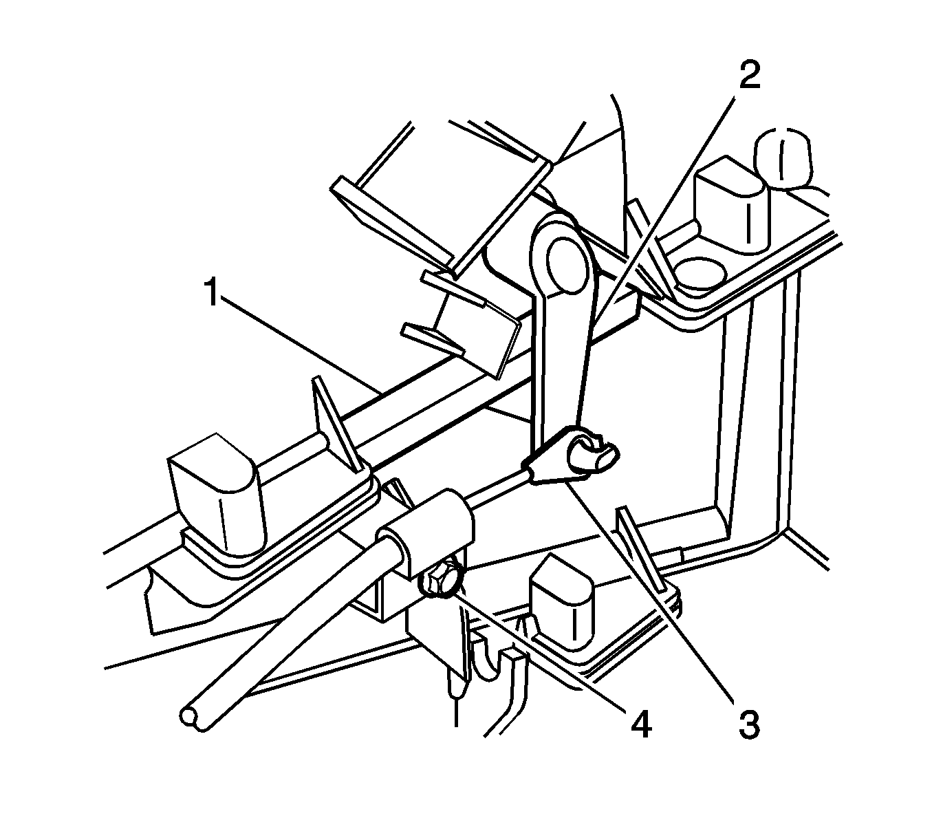
- Remove the screw (4) from the HVAC temperature control cable.
- Remove the control cable end (3) from the door lever (2).
- Remove the HVAC control assembly from the I/P carrier. Leave the harness connected to the HVAC control and position aside. Refer to Heater and Air Conditioning Control Replacement in HVAC Systems-Manual.
- Remove the radio from the I/P carrier. Refer to Radio Replacement in Entertainment.
- Remove the air distribution duct. Refer to Air Distributor Duct Replacement in HVAC Systems - Automatic.
- Remove the steering wheel. Refer to Steering Wheel Replacement in Steering Wheel and Column.
- Remove the tilt lever. Refer to Tilt Lever Replacement in Steering Wheel and Column.
- Remove the washer switch. Refer to Windshield Wiper and Washer Switch Replacement in Wipers/Washer Systems.
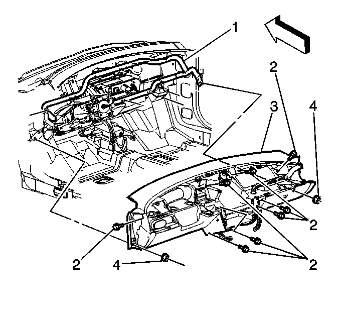
- Remove the screws (2) from the I/P carrier (3).
- Remove the nuts (4) from the I/P carrier (3).
- Remove the I/P carrier (3) from the lower tie bar (1).
- Remove the I/P carrier (3) from the vehicle.
Caution: Unless directed otherwise, the ignition and start switch must be in the OFF or LOCK position, and all electrical loads must be OFF before servicing any electrical component. Disconnect the negative battery cable to prevent an electrical spark should a tool or equipment come in contact with an exposed electrical terminal. Failure to follow these precautions may result in personal injury and/or damage to the vehicle or its components.
Caution: Refer to SIR Caution in the Preface section.


Installation Procedure
- Place the I/P carrier (3) into the vehicle.
- Install the I/P carrier (3) to the lower tie bar (1).
- Install the screws (2) to I/P carrier (3).
- Install the nuts (4) to the I/P carrier (3).
- Install the washer switch. Refer to Windshield Wiper and Washer Switch Replacement in Wipers/Washer Systems.
- Install the tilt lever. Refer to Tilt Lever Replacement in Steering Wheel and Column.
- Install the steering wheel. Refer to Steering Wheel Replacement in Steering Wheel and Column.
- Install the air distribution duct. Refer to Air Distributor Duct Replacement in HVAC Systems - Automatic.
- Install the radio to the I/P carrier. Refer to Radio Replacement in Entertainment.
- Install the HVAC control assembly to the I/P carrier. Refer to Heater and Air Conditioning Control Replacement in HVAC Systems-Manual.
- Install the end of the HVAC temperature control cable (3) to the door lever (2).
- Install the control cable screw (4).
- Install the I/P SIR module. Refer to Inflatable Restraint Instrument Panel Module Replacement in SIR.
- Install the I/P cluster. Refer to Instrument Cluster Replacement .
- Install the I/P trim pad. Refer to Instrument Panel Trim Pad Replacement .
- Enable the SIR system. Refer to SIR Disabling and Enabling and to SIR Disabling and Enabling in SIR.
- Connect the negative battery cable. Refer to Battery Negative Cable Disconnection and Connection in Engine Electrical.

Notice: Refer to Fastener Notice in the Preface section.
Tighten
Tighten the screws to 2.3 N·m (20 lb in).
Tighten
Tighten the nuts to 5 N·m (44 lb in).

Tighten
Tighten the screw to 2 N·m (18 lb in).
Instrument Panel Carrier Replacement Pontiac
Removal Procedure
- Disconnect the negative battery cable. Refer to Battery Negative Cable Disconnection and Connection in Engine Electrical.
- Disable the SIR system. Refer to SIR Disabling and Enabling and to SIR Disabling and Enabling in SIR.
- With a flat-bladed tool, remove the instrument panel (I/P) defroster grille.
- Remove the I/P outer trim cover screws.
- Remove the outer trim covers from the I/P carrier.
- Remove the radio from the I/P carrier. Refer to Radio Replacement in Entertainment.
- Remove the right I/P trim panel screws.
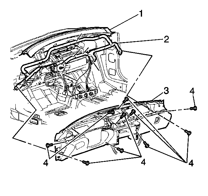
- Remove the right I/P trim panel from the I/P carrier (3).
- Remove the I/P trim pad. Refer to Instrument Panel Trim Pad Replacement .
- Remove the I/P SIR module. Refer to Inflatable Restraint Instrument Panel Module Replacement in SIR.
- Remove the screw (4) from the HVAC temperature control cable.
- Remove the control cable end (3) from the door lever (2).
- Remove the HVAC control assembly from the I/P carrier. Leave the harnesses connected to the HVAC control and position aside. Refer to Heater and Air Conditioning Control Replacement in HVAC Systems - Manual
- Remove the air distribution duct. Refer to Air Distributor Duct Replacement in HVAC Systems - Automatic.
- Remove the steering wheel. Refer to Steering Wheel Replacement in Steering Wheel and Column.
- Remove the tilt lever. Refer to Tilt Lever Replacement in Steering Wheel and Column.
- Remove the washer lever. Refer to Windshield Wiper and Washer Switch Replacement in Wipers/Washer Systems.
- Remove the screws (4) from the I/P carrier (3).
- Remove the I/P carrier (3) from the lower tie bar (2).
- Remove the I/P carrier (3) from the vehicle.
Caution: Unless directed otherwise, the ignition and start switch must be in the OFF or LOCK position, and all electrical loads must be OFF before servicing any electrical component. Disconnect the negative battery cable to prevent an electrical spark should a tool or equipment come in contact with an exposed electrical terminal. Failure to follow these precautions may result in personal injury and/or damage to the vehicle or its components.
Caution: Refer to SIR Caution in the Preface section.


Installation Procedure
- Place the I/P carrier (3) into the vehicle.
- Install the I/P carrier (3) to the tie bar (2).
- Install the screws (4) to the I/P carrier (3).
- Install the washer switch. Refer to Windshield Wiper and Washer Switch Replacement in Wipers/Washer Systems.
- Install the tilt lever. Refer to Tilt Lever Replacement in Steering Wheel and Column.
- Install the steering wheel. Refer to Steering Wheel Replacement in Steering Wheel and Column.
- Install the air distribution duct. Refer to Air Distributor Duct Replacement in HVAC Systems - Automatic.
- Install the HVAC control assembly from the I/P carrier. Refer to Heater and Air Conditioning Control Replacement in HVAC Systems - Manual.
- Install the end of the HVAC temperature control cable (3) to the door lever (2).
- Install the control cable screw (4).
- Install the I/P SIR module. Refer to Inflatable Restraint Instrument Panel Module Replacement in SIR.
- Install the I/P trim pad. Refer to Instrument Panel Trim Pad Replacement .
- Install the right I/P trim panel to the I/P carrier.
- Install the right I/P trim panel screws.
- Install the radio to the I/P carrier. Refer to Radio Replacement in Entertainment.
- Install the I/P outer trim covers.
- Install the I/P outer trim cover screws.
- Install the I/P defroster grille to the I/P trim pad.
- Enable the SIR system. Refer to SIR Disabling and Enabling and to SIR Disabling and Enabling in SIR.
- Connect the negative battery cable. Refer to Battery Negative Cable Disconnection and Connection in Engine Electrical.

Notice: Refer to Fastener Notice in the Preface section.
Tighten
Tighten the screws to 2.3 N·m (20 lb in).

Tighten
Tighten the screw to 2 N·m (18 lb in).
Tighten
Tighten the screws to 2.3 N·m (20 lb in).
Tighten
Tighten the screws to 2 N·m (18 lb in).
Press into place until fully seated.
