Removal Procedure
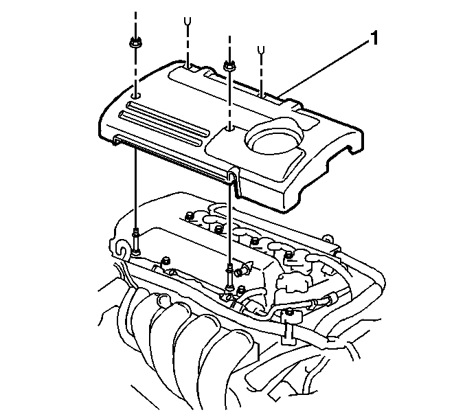
- Remove the 2 engine cover fasteners.
- Remove the 2 engine cover plastic retainers.
- Remove the engine cover (1) from the engine.
- Relieve the fuel pressure. Refer to Fuel Pressure Relief in Engine Controls-1.8L (LV6).
- Disconnect the negative battery cable.
- Remove the right side engine splash shield. Refer to Engine Splash Shield Replacement - Right Side in Body Front End.
- Remove the left side engine splash shield. Refer to Engine Splash Shield Replacement - Left Side in Body Front End.
- Drain the cooling system. Refer to Cooling System Draining and Filling in Engine Cooling.
- Drain the engine oil.
- Lower the vehicle.
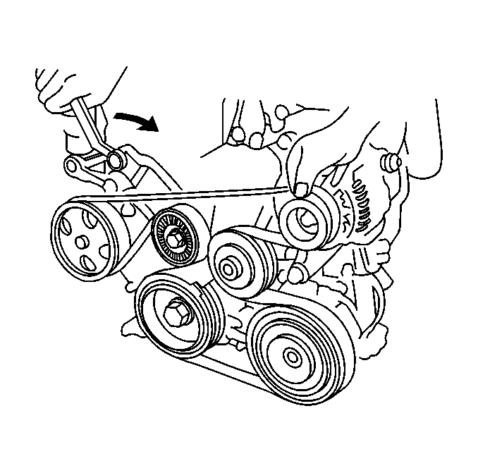
- Remove the serpentine drive belt. Refer to Drive Belt Replacement .
- Remove the generator. Refer to Generator Replacement in Engine Electrical.
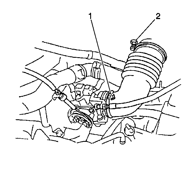
- Remove the accelerator cable from the throttle body (1).
- Disconnect the evaporative emission (EVAP) canister purge valve electrical connector.
- Disconnect the EVAP canister purge valve vacuum hoses.
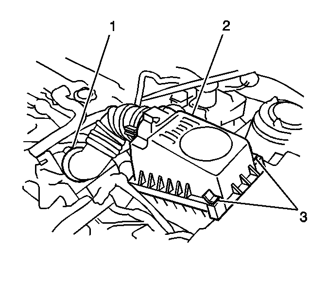
- Disconnect the air cleaner housing vacuum hose.
- Disconnect the intake air temperature (IAT) sensor.
- Remove the air cleaner hose and cap assembly (1).
- Disconnect the idle air control (IAC) Valve connector.
- Disconnect the manifold absolute pressure (MAP) sensor connector.
- Remove the two coolant bypass hose clamps from the throttle body.
- Remove the coolant bypass hoses.
- Disconnect the four fuel injector connectors (1).
- Remove the radiator inlet hose. Refer to Radiator Inlet Hose Replacement in Engine Cooling.
- Remove the following items from the intake manifold:
- Position the fuel injector harness above the intake manifold.
- Remove the intake manifold support bracket bolts and bracket.
- Remove the fuel injector harness brackets.
- Disconnect the oxygen sensor connector.
- Remove the oxygen sensor. Refer to Heated Oxygen Sensor 1 Replacement in Engine Controls-1.8L (LV6).
- Raise and support the vehicle. Refer to Lifting and Jacking the Vehicle in General Information.
- Remove the following items from the exhaust pipe at the manifold.
- Remove the exhaust pipe to manifold seal.
- On AWD, remove the 1 bolt (1) from the exhaust manifold to the support bracket.
- On 2WD, remove the exhaust manifold support bracket bolt.
- On all vehicles, lower the vehicle.
- Disconnect the two ignition coil connectors.
- Remove the ignition coil harness retaining bolts, then position harness aside.
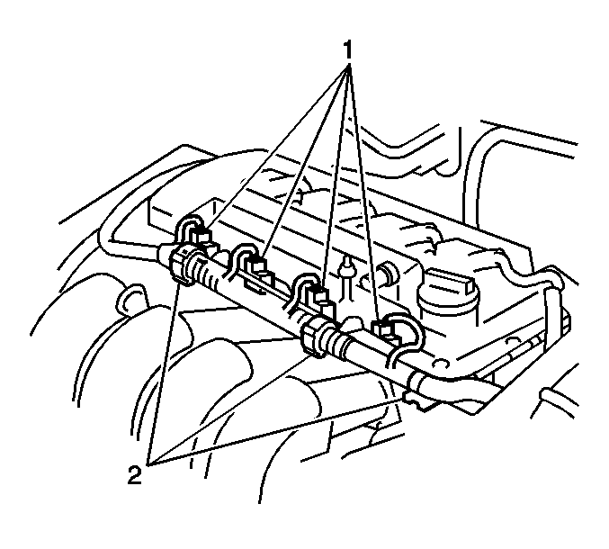
- Disconnect the fuel line at the fuel rail.
- Remove the injector fuel rail hold down clamp.
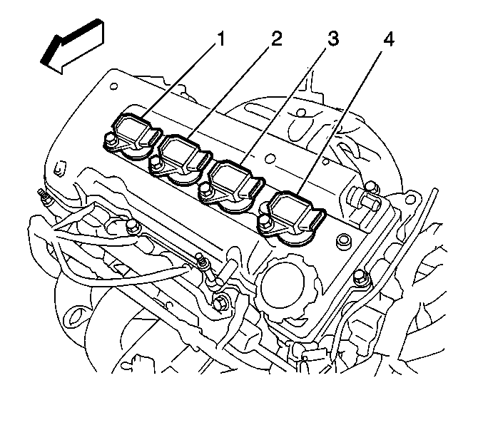
- Remove the ignition coils (1, 2, 3, 4).
- Remove the following items from the cylinder head:
- Remove the heater hose at the cylinder head.
- Remove the following items from the cylinder head:
- Disconnect the cam sensor electrical connector.
- Remove the following items:
- Disconnect the engine coolant temperature sensor electrical connector.
- Disconnect the camshaft position actuator solenoid valve electrical connector.
- Remove the bolt and camshaft position actuator solenoid valve and O-ring.
- Remove the camshaft position actuator oil filter plug, filter and O-ring.
- Remove the two PCV hoses from the cylinder head cover.
- Remove the cylinder head cover from the cylinder head. Refer to Cylinder Head Cover Replacement .
- Disconnect the power steering oil pressure switch connector.
- Raise and support the vehicle. Refer to Lifting and Jacking the Vehicle in General Information.
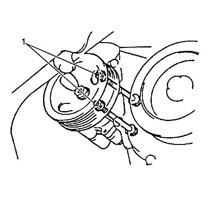
- Remove the two power steering pump through bolts and nuts (1).
- Remove the power steering pump.
- Position the power steering pump aside.
- Remove the crankshaft pulley. Refer to Crankshaft Pulley Replacement .
- Disconnect the crankshaft sensor electrical connector, then remove the following items:
- Lower the vehicle.
- Set the number 1 piston to top dead center.
- Align the camshaft timing sprockets.
- Support the engine with a floor jack. Be sure to place a block of wood between the floor jack and the engine.
- Remove the drive belt tensioner nut.
- Raise the engine, then remove the following items:
- Remove the following items:
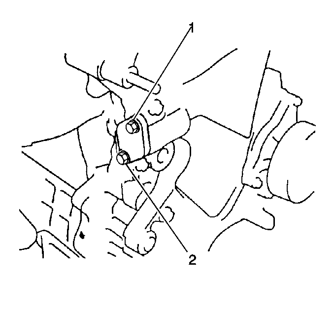
- Remove the timing chain tensioner bolts (1, 2).
- Remove the timing chain tensioner.
- Remove the engine mount bracket as follows:
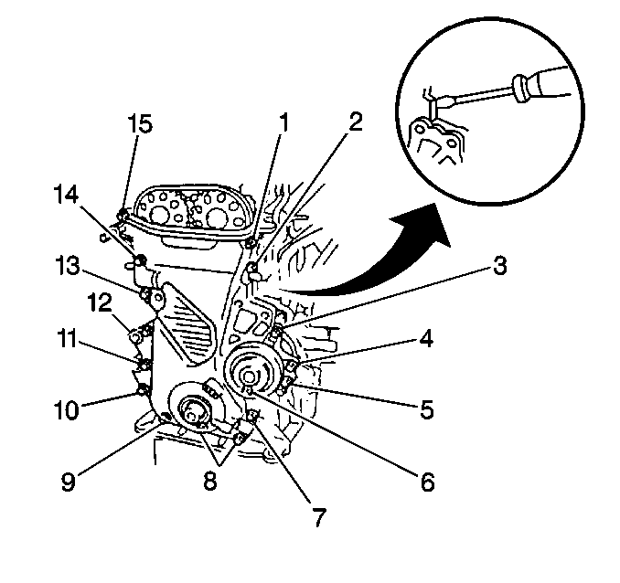
- Remove the timing chain cover bolts and nuts (1-15).
- Remove the timing chain cover.
- Remove the crank sensor reluctor.
- Remove the following items:
- Remove the following items:
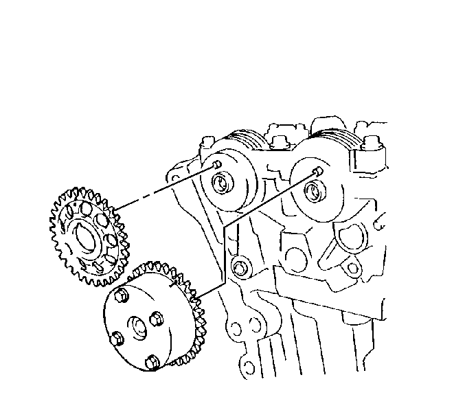
- Remove the camshaft sprocket bolts.
- Remove the camshaft sprockets.
- Remove the following items in sequence:
- Remove the camshafts.
- Remove the valve lifters. Keep the lifters in order so that the lifters can be reinstalled in the original location.
- Use a floor jack in order to raise the engine.
- Remove the intake manifold. Refer to Intake Manifold Replacement .
- Remove the exhaust manifold. Refer to Exhaust Manifold Replacement in Engine Exhaust.
- Remove the following items in sequence:
- Remove the cylinder head.
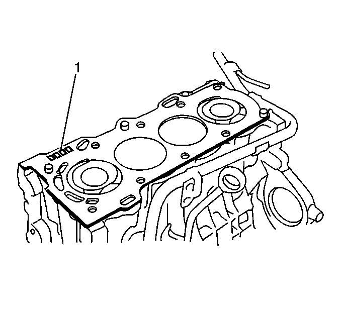
- Remove the cylinder head gasket (1).
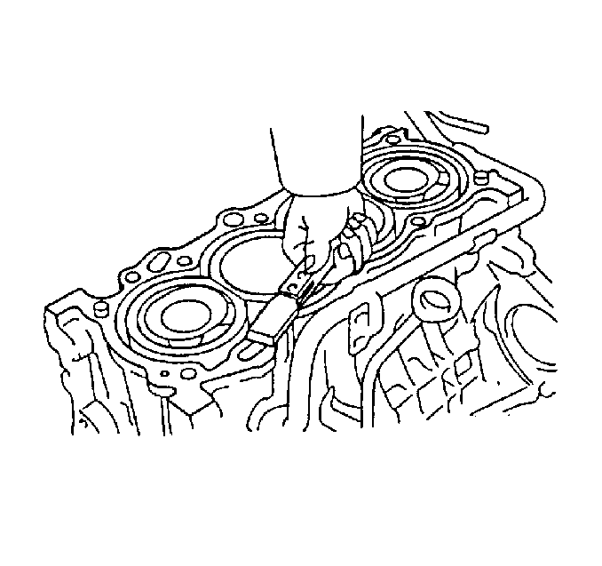
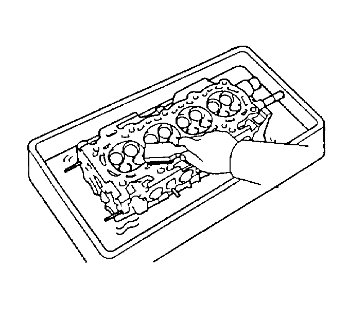
- Clean the cylinder block mating surfaces.
- Clean the cylinder head mating surface.
- Clean the timing chain cover mating surface.
Caution: Refer to Battery Disconnect Caution in the Preface section.
Disconnect the throttle position (TP) sensor connector.
| • | The 2 bolts (3, 4) |
| • | The fuel injector harness |
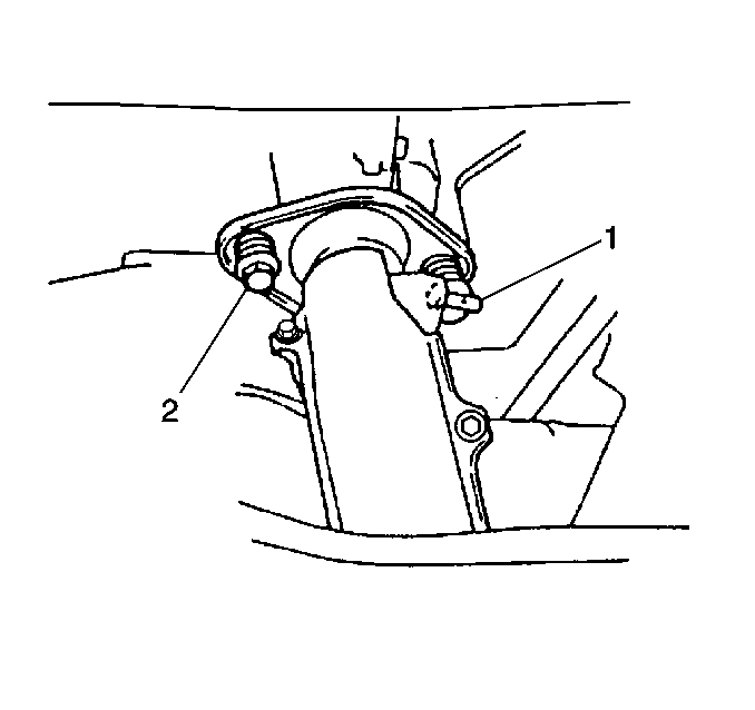
| • | The two bolts (1, 2) |
| • | The springs |
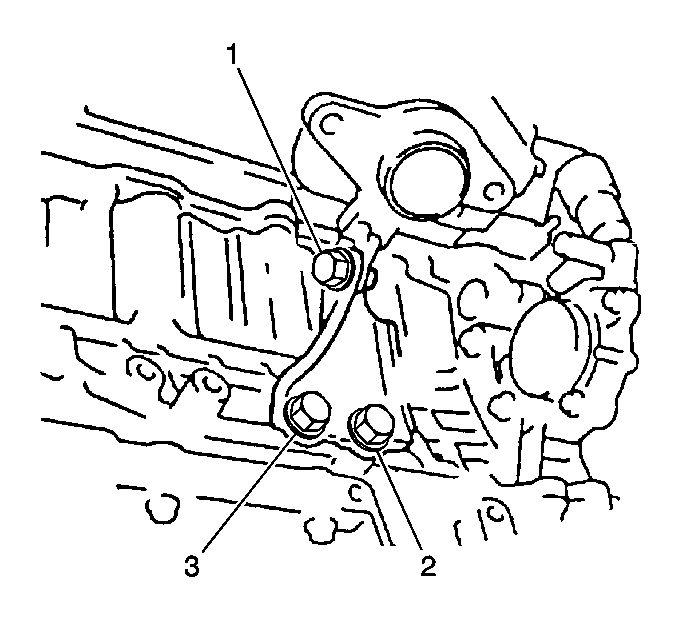
| • | The 3 bolts |
| • | The fuel rail |
| • | The 2 ground wire bolts |
| • | The ground wires |
| • | The one bolt |
| • | The water bypass pipe |
| • | The 1 bolt |
| • | The camshaft sensor |
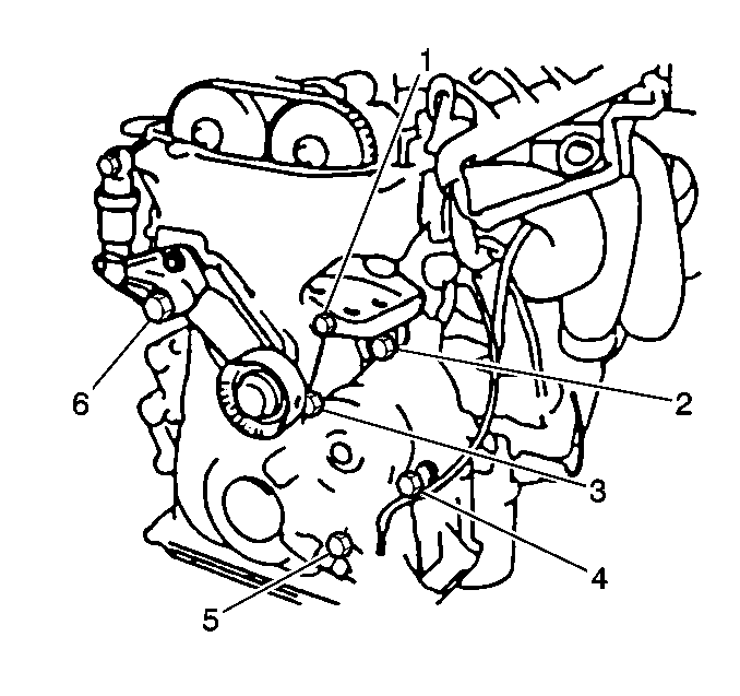
| • | The crankshaft position sensor bolt (5) |
| • | The crankshaft position sensor |
| • | The drive belt tensioner bolt |
| • | The drive belt tensioner |
| • | The 6 right side engine mount bolts |
| • | The engine mount |
| • | Remove the 3 bolts |
| • | Remove the bracket |
| • | The timing chain slipper bolt |
| • | The slipper |
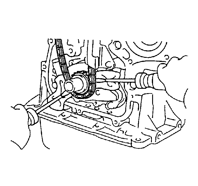
| • | The crankshaft sprocket |
| • | The timing chain |
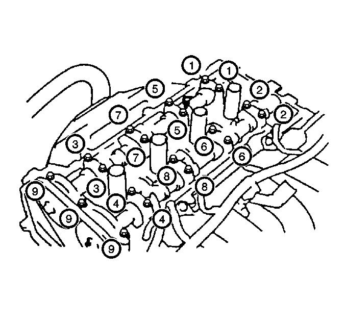
| • | The camshaft bearing cap bolts |
| • | The camshaft bearing caps |
Important: Use a wooden block in order to protect the oil pan when lifting the engine.
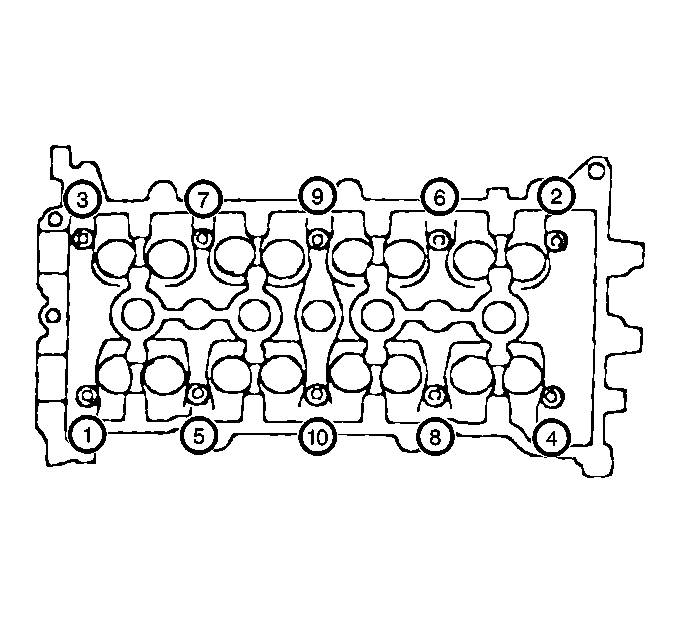
| • | The cylinder head bolts |
| • | The cylinder head washers |
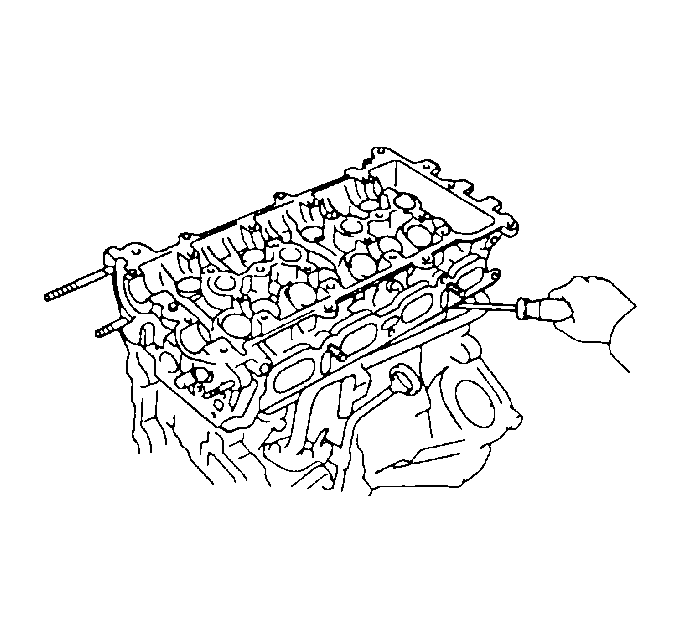
Installation Procedure
- Clean the threads in the cylinder block.
- Install the new cylinder head gasket on the cylinder block.
- Install the cylinder head on the cylinder block.
- Install the cylinder head bolts and washers into the cylinder head.
- Progressively torque the cylinder head bolts using 3 steps in the sequence shown.
- Install the intake manifold. Refer to Intake Manifold Replacement .
- Install the exhaust manifold. Refer to Exhaust Manifold Replacement in Engine Exhaust.
- Install the intake camshaft. Refer to Intake Camshaft and Valve Lifter Replacement .
- Install the exhaust camshaft. Refer to Exhaust Camshaft and Valve Lifter Replacement .
- Install the timing chain. Refer to Timing Chain and Sprocket Replacement .
- Install the timing chain housing. Refer to Timing Chain Housing Replacement .
- Install the crankshaft pulley. Refer to Crankshaft Pulley Replacement .
- Install the cylinder head cover. Refer to Cylinder Head Cover Replacement .
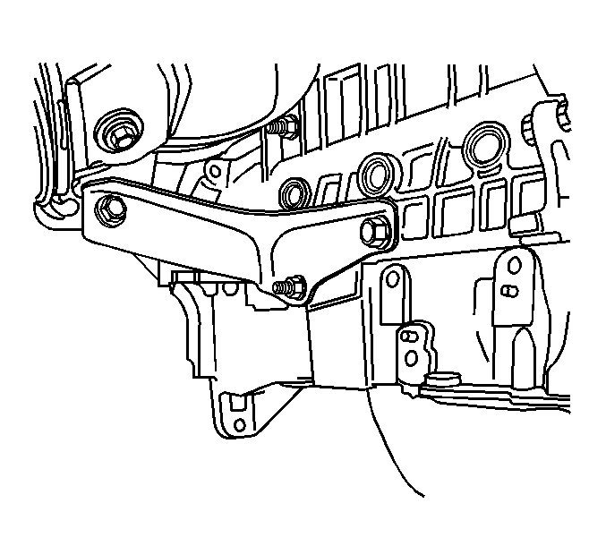
- Install the engine mount bracket as follows:
- Install the drive belt tensioner. Refer to Drive Belt Tensioner Replacement .
- Install the right side engine mount. Refer to Engine Mount Replacement .
- Install the crankshaft position sensor. Refer to Crankshaft Position Sensor Replacement in Engine Controls-1.8L (LV6).
- Install the power steering pump.
- Connect the power steering oil pressure switch electrical connector.
- Install the engine coolant temperature (ECT) sensor.
- Install the camshaft sensor.
- Use the 1 bolt in order to secure the camshaft sensor.
- Install the camshaft position actuator O-ring, filter and oil filter.
- Install a new O-ring and the camshaft position actuator solenoid.
- Connect the camshaft position actuator solenoid valve electrical connector.
- Connect the engine coolant temperature sensor electrical connector.
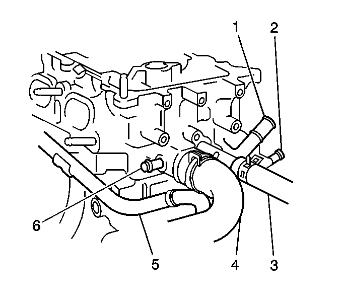
- Install the water bypass pipe (1) to the cylinder head.
- Use the 1 bolt in order to secure the coolant bypass pipe to the cylinder head.
- Install the heater hose to the cylinder head.
- Install the engine ground wires to the cylinder head.
- Use the 2 bolts in order to secure the engine ground wires.
- Install the fuel rail to the cylinder head.
- Use the 3 bolts in order to secure the fuel rail.
- Connect the fuel line to the fuel rail.
- Install the heater hose to the cylinder head.
- Install the 4 ignition coils (1, 2, 3, 4).
- Connect the ignition coil connectors.
- Remove the engine support fixture.
- Raise and support the vehicle.
- On AWD, install the one bolt (1) from the manifold to the support bracket.
- On 2WD, install the exhaust manifold support bracket bolt.
- Use a new seal in order to install the exhaust pipe to the exhaust manifold.
- Use the 2 bolts and two springs (1, 2) in order to secure the exhaust pipe.
- Install the left side engine splash shield. Refer to Engine Splash Shield Replacement - Left Side in Body Front End.
- Install the right side engine splash shield. Refer to Engine Splash Shield Replacement - Right Side in Body Front End.
- Lower the vehicle.
- Install the oxygen sensor. Refer to Heated Oxygen Sensor 1 Replacement in Engine Controls-1.8L (LV6).
- Install the injector harness brackets.
- Connect all of the necessary vacuum hoses.
- Install the intake manifold support bracket.
- Use the support bracket bolts in order to secure the intake manifold support bracket.
- Install the fuel injector harness to the intake manifold.
- Use the three bolts in order to secure the fuel injector harness.
- Install the radiator inlet hose. Refer to Radiator Inlet Hose Replacement in Engine Cooling.
- Connect the 4 fuel injector connectors.
- Connect the temperature sensor connector.
- Install the 2 coolant bypass hoses to the throttle body.
- Use the 2 hose clamps in order to secure the two coolant bypass hoses.
- Connect the MAP sensor connector.
- Connect the IAC valve connector.
- Connect the TP sensor connector.
- Install the air cleaner hose and cap assembly.
- Connect the IAT sensor connector.
- Install the accelerator cable to the throttle body.
- Install the generator (1). Refer to Generator Replacement in Engine Electrical.
- Install the serpentine drive belt. Refer to Drive Belt Replacement .
- Refill the engine oil.
- Refill the engine coolant.
Notice: This engine uses special torque to yield head bolts. This design bolt requires a special tightening procedure. Failure to follow the given procedure will cause head gasket failure and possible engine damage.
Notice: This bolt is designed to permanently stretch when tightened, and therefore MUST be replaced anytime it is removed. The correct part number fastener must be used to replace this type of fastener. Do not use a bolt that is stronger in this application. If the correct bolt is not used, the parts will not be tightened correctly. The system or the components may be damaged.
Notice: Refer to Fastener Notice in the Preface section.
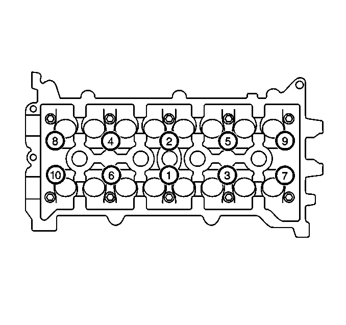
1st Pass
Tighten the cylinder head bolts to 25 N·m (18 lb ft).
2nd Pass
Tighten the cylinder head bolts to 49 N·m (36 lb ft).
3rd Pass
After reaching the torque of 49 N·m (36 lb ft). Use
a J 36660-A
and tighten the cylinder
head bolts an additional 90 degrees.
| • | Position the engine mount bracket |
| • | Install the 3 bolts |
Tighten
Tighten the bolts to 47 N·m (35 lb ft).
Tighten
Tighten the power steering pump bolts to 37 N·m (27 lb ft).
Tighten
Tighten the camshaft sensor bolt to 15 N·m (11 lb ft).
Tighten
Tighten the camshaft position actuator solenoid valve bolt to 15 N·m
(11 lb ft).
Tighten
Tighten the coolant bypass pipe to 15 N·m (11 lb ft).
Tighten
Tighten the ground wire bolts to 15 N·m (11 lb ft).
Tighten
Tighten the fuel rail bolts to 14 N·m (10 lb ft).


Tighten
Tighten the exhaust support bracket bolt to 35 N·m (26 lb ft).

Tighten
Tighten the exhaust support bracket bolt to 50 N·m (37 lb ft).

Tighten
Tighten the exhaust pipe flange bolts to 62 N·m (46 lb ft).
Tighten
Tighten the intake support bracket bolts to 50 N·m (37 lb ft).
Tighten
Tighten the fuel injector harness bolts to 12 N·m (106 lb in).

