Steering Gear Replacement FWD
Removal Procedure
- LOCK the steering column and verify the front wheels are in the straight ahead position.
- Move the silencer pad away from the steering column.
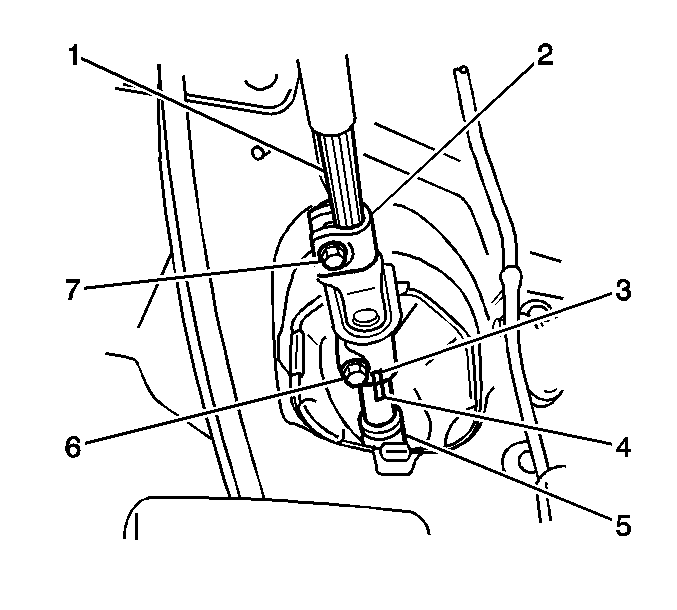
- Use paint in order to place match marks on the steering shaft coupling (3) and on the intermediate shaft (4).
- Loosen the upper coupling bolt (7).
- Remove the lower coupling bolt (6).
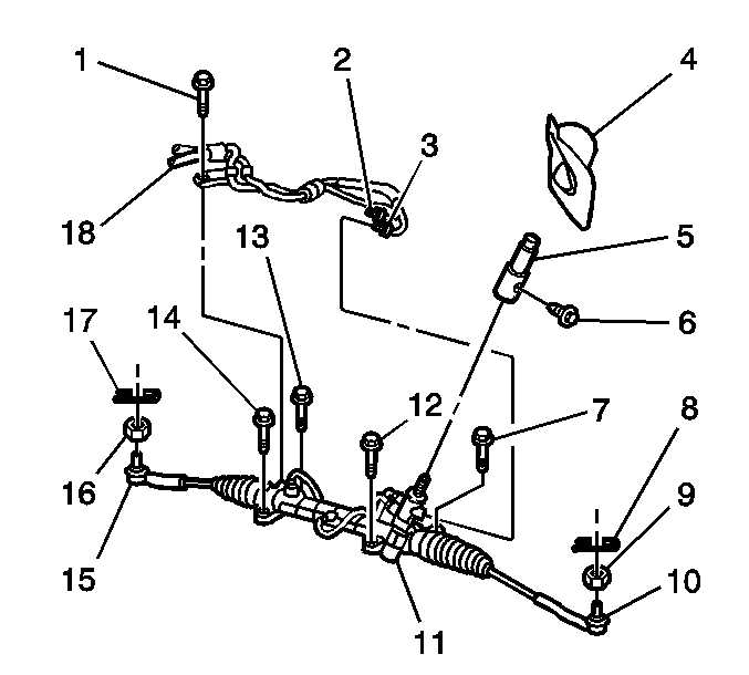
- Remove the steering column hole cover (4) from the bulkhead.
- Install the Engine Support Fixture. Refer to Engine Support Fixture in Engine Mechanical - 1.8L (LV6) or to Engine Support Fixture in Engine Mechanical - 1.8L (LNK).
- Raise and support the vehicle. Refer to Lifting and Jacking the Vehicle in General Information.
- Remove the front tire and wheel assemblies. Refer to Tire and Wheel Removal and Installation in Tires and Wheels.
- Remove the left engine splash shield. Refer to Engine Splash Shield Replacement - Left Side in Body Front End.
- Remove the right engine splash shield. Refer to Engine Splash Shield Replacement - Right Side in Body Front End.
- Remove the 2 outer tie rod ends (10,15). Refer to Rack and Pinion Outer Tie Rod End Replacement .
- Place a drain pan under the vehicle in order to collect the fluid from the power steering system.
- Remove the pressure and return pipes (2,3) from the steering gear.
- Remove the bolt and the pipe bracket from the steering gear.
- Remove the following components together as a unit. Refer to Front Suspension Crossmember Replacement in Frame and Underbody.
- Remove the bolt and the rear engine mount insulator from the crossmember.
- Remove the 3 bolts and the rear engine mount bracket from the crossmember.
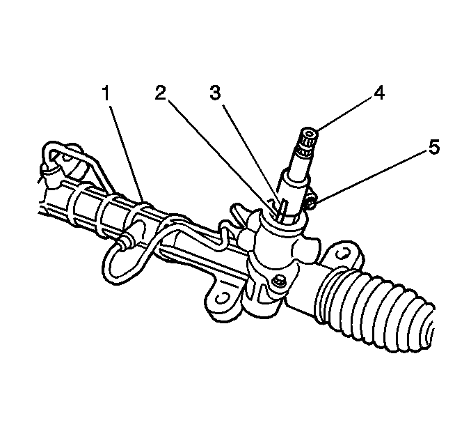
- Use paint in order to place match marks on the intermediate shaft (3) and on the steering gear (2).
- Remove the bolt (5).
- Remove the intermediate shaft (4).
- Remove the 4 bolts and the steering gear from the crossmember.
Notice: The steering column must be in the LOCK position before disconnecting
the following components:
• The steering column • The steering shaft coupling • The intermediate shaft • The lower steering shaft


Notice: Refer to Power Steering Hose Disconnected Notice in the Preface section.
| • | The steering gear |
| • | The intermediate steering shaft |
| • | The front suspension crossmember |
| • | The trans support |
| • | The 2 control arms |
| • | The front stabilizer shaft |

Installation Procedure
- Install the rear engine mount bracket to the crossmember.
- Install the 3 bolts to the rear engine mount bracket.
- Install the rear engine mount insulator to the crossmember.
- Install the bolt to the rear engine mount insulator.
- If you are replacing the steering gear or the intermediate shaft, copy the match marks from the old parts to the same locations on the new parts.
- Install the steering gear (11) and the 4 bolts (7,12,13,14) to the crossmember.
- Install the intermediate shaft (5) to the steering gear. Align the match marks.
- Install the bolt (6) to the intermediate shaft.
- Install the steering column hole cover (4) to the bulkhead.
- Install the following components as a unit. Refer to Front Suspension Crossmember Replacement in Frame and Underbody.
- Install the 2 outer tie rod ends (10,15). Refer to Rack and Pinion Outer Tie Rod End Replacement .
- Install the pressure and return pipes (18) to the steering gear.
- Install the pipe bracket bolt (1).
- Install the left engine splash shield. Refer to Engine Splash Shield Replacement - Left Side in Body Front End.
- Install the right engine splash shield. Refer to Engine Splash Shield Replacement - Right Side in Body Front End.
- Install the front tire and wheel assemblies. Refer to Tire and Wheel Removal and Installation in Tires and Wheels.
- Lower the vehicle.
- Remove the Engine Support Fixture. Refer to Engine Support Fixture in Engine Mechanical - 1.8L (LV6) or to Engine Support Fixture in Engine Mechanical - 1.8L (LNK).
- Align the match marks on the intermediate shaft (4) and on the steering shaft coupling (3).
- Install the lower coupling bolt (6).
- Tighten the upper coupling bolt (7).
- Place the silencer pad into the correct position.
- Fill the power steering fluid reservoir. Refer to Checking and Adding Power Steering Fluid .
- Bleed the power steering system. Refer to Power Steering System Bleeding .
- Inspect the power steering system for leaks. Repair as necessary.
- Measure the wheel alignment. Adjust as necessary. Refer to Wheel Alignment Measurement in Wheel Alignment.
Notice: Refer to Fastener Notice in the Preface section.
Tighten
Tighten the bolts to 64 N·m (47.2 lb ft).
Tighten
Tighten the bolt to 87 N·m (64.2 lb ft).

Tighten
Tighten the bolts to 58 N·m (42.8 lb ft).
Tighten
Tighten the bolt to 35 N·m (25.8 lb ft).
| • | The steering gear |
| • | The intermediate steering shaft |
| • | The front suspension crossmember |
| • | The trans support |
| • | The 2 control arms |
| • | The front stabilizer shaft |
Notice: Refer to Installing Hoses without Twists or Bends Notice in the Preface section.
Tighten
Tighten the pipe nuts to 23 N·m (17.0 lb ft).
Tighten
Tighten the bolt to 7.8 N·m (69.04 lb in).

Tighten
Tighten the bolt to 35 N·m (25.8 lb ft).
Tighten
Tighten the bolt to 35 N·m (25.8 lb ft).
Notice: Refer to Using Proper Power Steering Fluid Notice in the Preface section.
Notice: Refer to Air in the Power Steering System Notice in the Preface section.
Steering Gear Replacement AWD
Removal Procedure
- LOCK the steering column and verify the front wheels are in the straight ahead position.
- Move the silencer pad away from the steering column.
- Use paint in order to place match marks on the steering shaft coupling (3) and on the steering gear pinion shaft (4).
- Loosen the upper coupling bolt (7).
- Remove the lower coupling bolt (6).
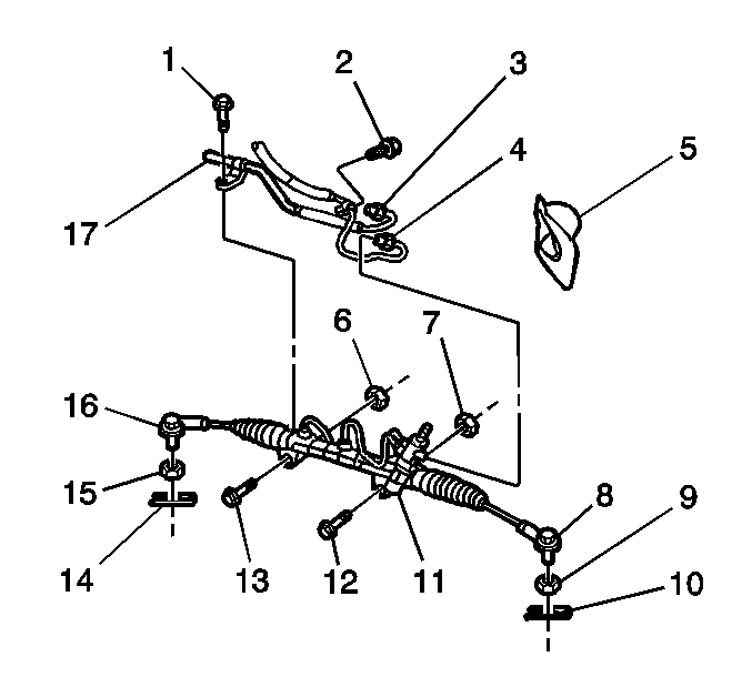
- Remove the steering column hole cover (5) from the bulkhead.
- Install the Engine Support Fixture. Refer to Engine Support Fixture in Engine Mechanical - 1.8L (LV6).
- Raise and support the vehicle. Refer to Lifting and Jacking the Vehicle in General Information.
- Remove the front tire and wheel assemblies. Refer to Tire and Wheel Removal and Installation in Tires and Wheels.
- Remove the left engine splash shield. Refer to Engine Splash Shield Replacement - Left Side in Body Front End.
- Remove the right engine splash shield. Refer to Engine Splash Shield Replacement - Right Side in Body Front End.
- Remove the 2 outer tie rod ends (8,16). Refer to Rack and Pinion Outer Tie Rod End Replacement .
- Place a drain pan under the vehicle in order to collect the fluid from the power steering system.
- Remove the pressure and return pipes (3,4) from the steering gear.
- Remove the 2 bolts (1,2) and the pipe brackets from the steering gear.
- Remove the following components together as a unit. Refer to Front Suspension Crossmember Replacement in Frame and Underbody.
- Remove the bolt and the rear engine mount insulator from the crossmember.
- Remove the 3 bolts and the rear engine mount bracket from the crossmember.
- Remove the 2 bolts (12,13) and the steering gear from the crossmember.
Notice: The steering column must be in the LOCK position before disconnecting
the following components:
• The steering column • The steering shaft coupling • The intermediate shaft • The lower steering shaft


Notice: Refer to Power Steering Hose Disconnected Notice in the Preface section.
| • | The steering gear |
| • | The front suspension crossmember |
| • | The trans support |
| • | The 2 control arms |
| • | The front stabilizer shaft |
Installation Procedure
- Install the rear engine mount bracket to the crossmember.
- Install the 3 bolts to the rear engine mount bracket.
- Install the rear engine mount insulator to the crossmember.
- Install the bolt to the rear engine mount insulator.
- If you are replacing the steering gear, copy the match marks from the old parts to the same locations on the new parts.
- Install the steering gear (11) to the crossmember.
- Install the 2 bolts (12,13) to the steering gear.
- Install the steering column hole cover (5) to the bulkhead.
- Install the following components as a unit. Refer to Front Suspension Crossmember Replacement in Frame and Underbody.
- Install the 2 outer tie rod ends (8,16). Refer to Rack and Pinion Outer Tie Rod End Replacement .
- Install the pressure and return pipes (3,4) to the steering gear.
- Install the 2 pipe bracket bolts (1,2).
- Install the left engine splash shield. Refer to Engine Splash Shield Replacement - Left Side in Body Front End.
- Install the right engine splash shield. Refer to Engine Splash Shield Replacement - Right Side in Body Front End.
- Install the front tire and wheel assemblies. Refer to Tire and Wheel Removal and Installation in Tires and Wheels.
- Lower the vehicle.
- Remove the Engine Support Fixture. Refer to Engine Support Fixture in Engine Mechanical - 1.8L (LV6).
- Align the match marks on the steering gear pinion shaft (4) and on the steering shaft coupling (3).
- Install the lower coupling bolt (6).
- Tighten the upper coupling bolt (7).
- Place the silencer pad into the correct position.
- Fill the power steering fluid reservoir. Refer to Checking and Adding Power Steering Fluid .
- Bleed the power steering system. Refer to Power Steering System Bleeding .
- Inspect the power steering system for leaks. Repair as necessary.
- Measure the wheel alignment. Adjust as necessary. Refer to Wheel Alignment Measurement in Wheel Alignment.
Notice: Refer to Fastener Notice in the Preface section.
Tighten
Tighten the bolts to 64 N·m (47.2 lb ft).
Tighten
Tighten the bolt to 87 N·m (64.2 lb ft).

Tighten
Tighten the bolts to 82 N·m (60.5 lb ft).
| • | The steering gear |
| • | The front suspension crossmember |
| • | The trans support |
| • | The 2 control arms |
| • | The front stabilizer shaft |
Notice: Refer to Installing Hoses without Twists or Bends Notice in the Preface section.
Tighten
Tighten the pipe nuts to 23 N·m (17.0 lb ft).
Tighten
Tighten the bolts to 7.8 N·m (69.04 lb in).

Tighten
Tighten the bolt to 35 N·m (25.8 lb ft).
Tighten
Tighten the bolt to 35 N·m (25.8 lb ft).
Notice: Refer to Using Proper Power Steering Fluid Notice in the Preface section.
Notice: Refer to Air in the Power Steering System Notice in the Preface section.
