For 1990-2009 cars only
Disabling Zone 4
- Turn the steering wheel so that the vehicle wheels are pointing straight ahead.
- Turn the ignition switch to the OFF position.
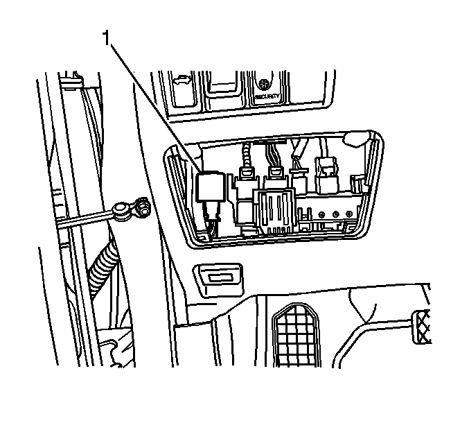
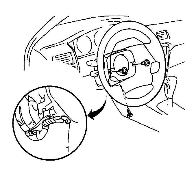
- Locate and remove the AM2 fuse from the junction block (1), which is located near the base of the steering column.
- Disconnect the battery negative cable. Refer to Battery Negative Cable Disconnection and Connection in Engine Electrical.
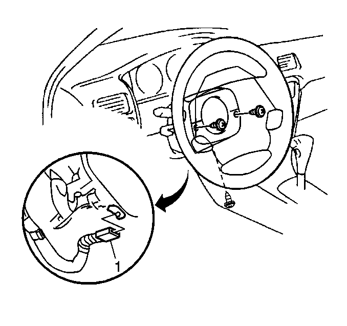
- Release the inflatable restraint steering wheel module coil connector locking mechanism.
- Disconnect the inflatable restraint steering wheel module coil connector C3 (1).
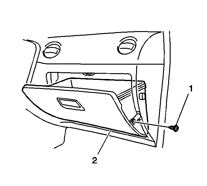
- Remove the instrument panel (I/P) compartment (2). Refer to Instrument Panel Compartment Replacement in Instrument Panel, Gages, and Console.
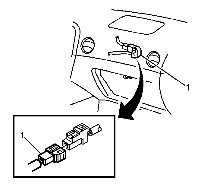
- Release then unlock the I/P module connector (1).
- Disconnect the I/P module pigtail.
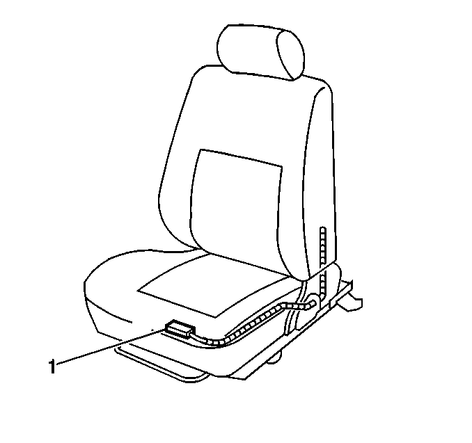
- Release and unlock the driver and passenger seat module connectors (1).
- Disconnect the driver and passenger seat modules.
- Remove the quarter upper trim panel. Refer to Rear Quarter Upper Trim Panel Replacement .
- Remove the center pillar upper trim panel. Refer to Center Pillar Upper Trim Panel Replacement .
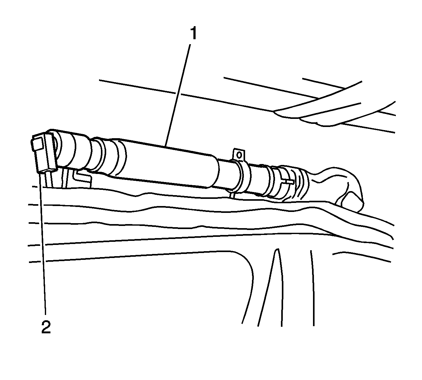
- Disconnect the left and right roof rail module wiring harness yellow connectors (2) from the roof rail modules (1).
Important: With the SIR fuse removed and the ignition switch in the ON position, the AIR BAG warning indicator illuminates. This is normal operation, and does not indicate an SIR system malfunction.
Enabling Zone 4
- Remove the key from the ignition switch.
- Connect the left and right roof rail module wiring harness yellow connectors (2) to the roof rail modules (1).
- Install the center pillar upper trim panel. Refer to Center Pillar Upper Trim Panel Replacement .
- Install the quarter upper trim panel. Refer to Rear Quarter Upper Trim Panel Replacement .
- Install the yellow 2-way connectors to the driver and passenger seat modules (1).
- Connect the connectors and lock the connectors with the connector lock levers.
- Install the yellow 2-way connector to the inflatable restraint I/P module pigtail (1).
- Install the I/P compartment (2). Refer to Instrument Panel Compartment Replacement in Instrument Panel, Gages, and Console.
- Install the yellow 2-way connector (1) for the inflatable restraint steering wheel module coil.
- Install the lower steering column trim cover.
- Connect the battery negative cable. Refer to Battery Negative Cable Disconnection and Connection in Engine Electrical.
- Install the AM2 fuse into the junction block (1).
- Use caution while reaching in and turn the ignition switch to the ON position.
- The AIR BAG indicator will flash then turn OFF.
- Perform the Diagnostic System Check - Vehicle if the AIR BAG warning indicator does not operate as described. Refer to Diagnostic System Check - Vehicle .


Connect the connector and lock the connector with the connector lock lever.

Connect the connector and lock the connector with the connector lock lever.

