Removal Procedure
Notice: Refer to Steering Column in Lock Position Notice in the Preface section.
- LOCK the steering column. Verify the front wheels are in the straight ahead
position.

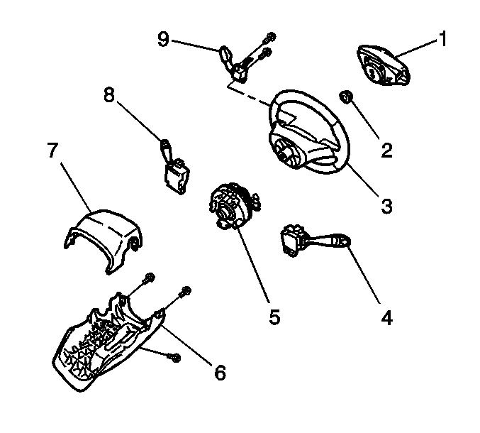
- Remove the inflatable restraint steering wheel module (1). Refer to
Inflatable Restraint Steering Wheel Module Replacement
.
- Remove the steering wheel (3). Refer to
Steering Wheel Replacement
.
- Remove the trim covers (6,7) from the steering column. Refer to
Steering Column Trim Covers Replacement
.
- Remove the turn signal and headlamp dimmer switch (4). Refer to
Headlamp Switch Replacement
in Lighting Systems.
- Remove the windshield wiper and washer switch (8). Refer to
Windshield Wiper and Washer Switch Replacement
in Wipers/Washer Systems.
- Remove the SIR coil (5). Refer to
Inflatable Restraint Steering Wheel Module Coil Replacement
in SIR.

- If the vehicle has an automatic transmission,
complete the following steps:
| 8.1. | Insert the key into the cylinder. |
| 8.2. | Turn the key to the ACC position. |
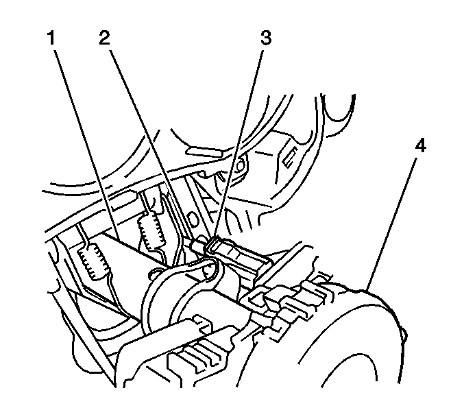
| 8.3. | Push in the release button (3). |
| 8.4. | Disconnect the park lock cable (2). |
| 8.5. | Remove the key from the cylinder. |
| 8.6. | Lock the steering column in the original position. |
- Move the silencer pad away from the steering column.

- Use paint in order to place match marks
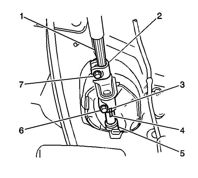
on the steering shaft coupling (3) and on the shaft (4).
- Loosen the upper bolt (7) on the coupling.
- Remove the lower bolt (6) from the coupling.
- Move the coupling onto the steering column shaft (1).
- Disconnect the connectors on the steering column.
- Separate the wire harness clamps from the steering column.
Notice: Once the steering column is removed from the vehicle, the column is
extremely susceptible to damage. Dropping the column assembly on the end could
collapse the steering shaft or loosen the plastic injections, which maintain
column rigidity. Leaning on the column assembly could cause the jacket to
bend or deform. Any of the above damage could impair the columns collapsible
design. Do NOT hammer on the end of the shaft, because hammering could loosen
the plastic injections, which maintain column rigidity. If you need to remove
the steering wheel, refer to the Steering Wheel Replacement procedure in this
section.
- Remove the 3 bolts and the steering column from the vehicle.

- If you are replacing the column, complete
the following steps:
| 17.1. | Use paint in order to place match marks on the coupling and on the steering
column shaft. |
| 17.2. | Remove the upper bolt and the coupling from the column shaft. |
| 17.3. | Use paint in order to place match marks on the steering column housing
and on the steering column shaft. |
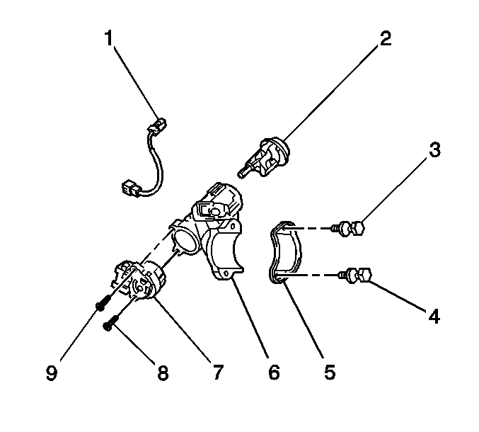
| 17.4. | Use a screw extractor or a center punch in order to remove the bolts (3,4)
and the ignition lock cylinder case. |
Installation Procedure
- Verify the front tires have not moved since the removal of the steering
column.
- If you are replacing the steering column, copy the match marks from the
old column to the new column.

- If you removed the ignition lock cylinder
case, install the following components to the steering column:
| 3.1. | The ignition lock cylinder case (6) |
| 3.2. | The ignition and key alarm switch (1) |
| 3.3. | The 2 screws (8,9) and the ignition switch (7) |
| 3.4. | The ignition lock cylinder case clamp (5) |
| 3.5. | 2 NEW tapered head bolts |
Tighten the bolts until the bolt heads break off.
- If you removed the ignition switch cylinder (2), complete the following
steps:
| 4.1. | Insert the key into the cylinder. |
| 4.2. | Turn the key to the ACC position. |
| 4.3. | Install the cylinder into the case. |
| 4.4. | Verify the stop pin engages the case. |
| 4.5. | Remove the key from the cylinder. |
- Attempt to turn the steering column shaft. Verify the steering column
locks.
- Insert the key into the cylinder.
- Attempt to turn the steering column shaft and turn the key to the ACC
position. Verify the steering column unlocks.
- Remove the key from the cylinder.
- Align the match marks and lock the steering column in the original position.

- If you removed the steering shaft coupling (2),
align the match marks on the coupling and on the steering column shaft. Install the
coupling to the steering column shaft.
Notice: Refer to Fastener Notice in the Preface section.
Caution: In order to ensure the intended function of the steering
column in a vehicle during a crash and in order to avoid personal injury to
the driver, perform the following:
| • | Tighten the steering column lower fasteners before you tighten
the steering column upper fasteners. Failure to do this can damage the steering
column. |
| • | Tighten the steering column fasteners to the specified torque.
Overtightening the upper steering column fasteners could affect the steering
column collapse. |
- Install the steering column and the 3 bolts to the vehicle.
Tighten
- Tighten the lower bolt to 21 N·m (15.5 lb ft).
- Tighten the 2 upper bolts to 21 N·m (15.5 lb ft).
- Align the match marks on the coupling and on the shaft (4).
- Lower the coupling onto the shaft.
- Install the 2 coupling bolts.
Tighten
- Tighten the lower bolt to 35 N·m (25.8 lb ft).
- Tighten the upper bolt to 35 N·m (25.8 lb ft).
- Place the silencer pad in the correct position.

- If the vehicle has an automatic transmission,
complete the following steps:
| 16.1. | Insert the key into the cylinder. |
| 16.2. | Turn the key to the ACC position. |
| 16.3. | Insert the park lock cable (2). Verify the release button (3)
engages. |
| 16.4. | Verify the key will not rotate to the LOCK position unless the shifter
is in the PARK position. |
| 16.5. | Remove the key from the cylinder. |
| 16.6. | Lock the steering column in the original position. |

- Install the SIR coil (5). Refer to
Inflatable Restraint Steering Wheel Module Coil Replacement
in SIR.
- If necessary, center the SIR coil. Refer to
Inflatable Restraint Steering Wheel Module Coil Centering
.
- Install the windshield wiper and washer switch (8). Refer to
Windshield Wiper and Washer Switch Replacement
in Wipers/Washer Systems.
- Install the turn signal and headlamp dimmer switch (4). Refer to
Headlamp Switch Replacement
in Lighting Systems.
- Install the steering wheel (3). Refer to
Steering Wheel Replacement
.
- Install the inflatable restraint steering wheel module (1). Refer
to
Inflatable Restraint Steering Wheel Module Replacement
.
- Connect the connectors on the steering column.
- Install the wire harness clamps to the steering column.
- Install the trim covers (6,7) to the column. Refer to
Steering Column Trim Covers Replacement
.


