Coolant Pump Replacement 2.4L
Special Tools
EN 46104 Water Pump Pulley Holding Tool
Inspection Procedure
- Remove the radiator surge tank assembly. Refer to Radiator Surge Tank Replacement.
- Remove the generator assembly. Refer to Generator Replacement.
- Remove the right engine mounting insulator subassembly. Refer to Engine Mount Replacement.
- Remove water pump pulley. Refer to Coolant Pump Replacement.
- Inspect water pump assembly.
- Visually check the drain hole (2) and air hole for coolant leakage.
- Turn the pulley, and then check that the water pump bearing moves smoothly without making a "click" sound.
- Install the water pump pulley.
- Install the right engine mounting insulator subassembly. Refer to Engine Mount Replacement.
- Install the generator assembly. Refer to Generator Replacement.
- Install the radiator surge tank assembly. Refer to Radiator Surge Tank Replacement.
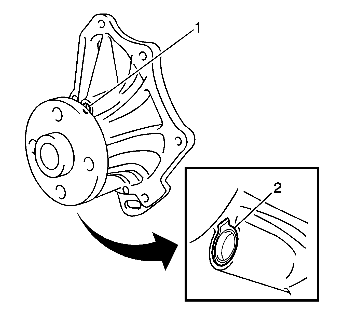
If leakage is found, replace the water pump assembly.
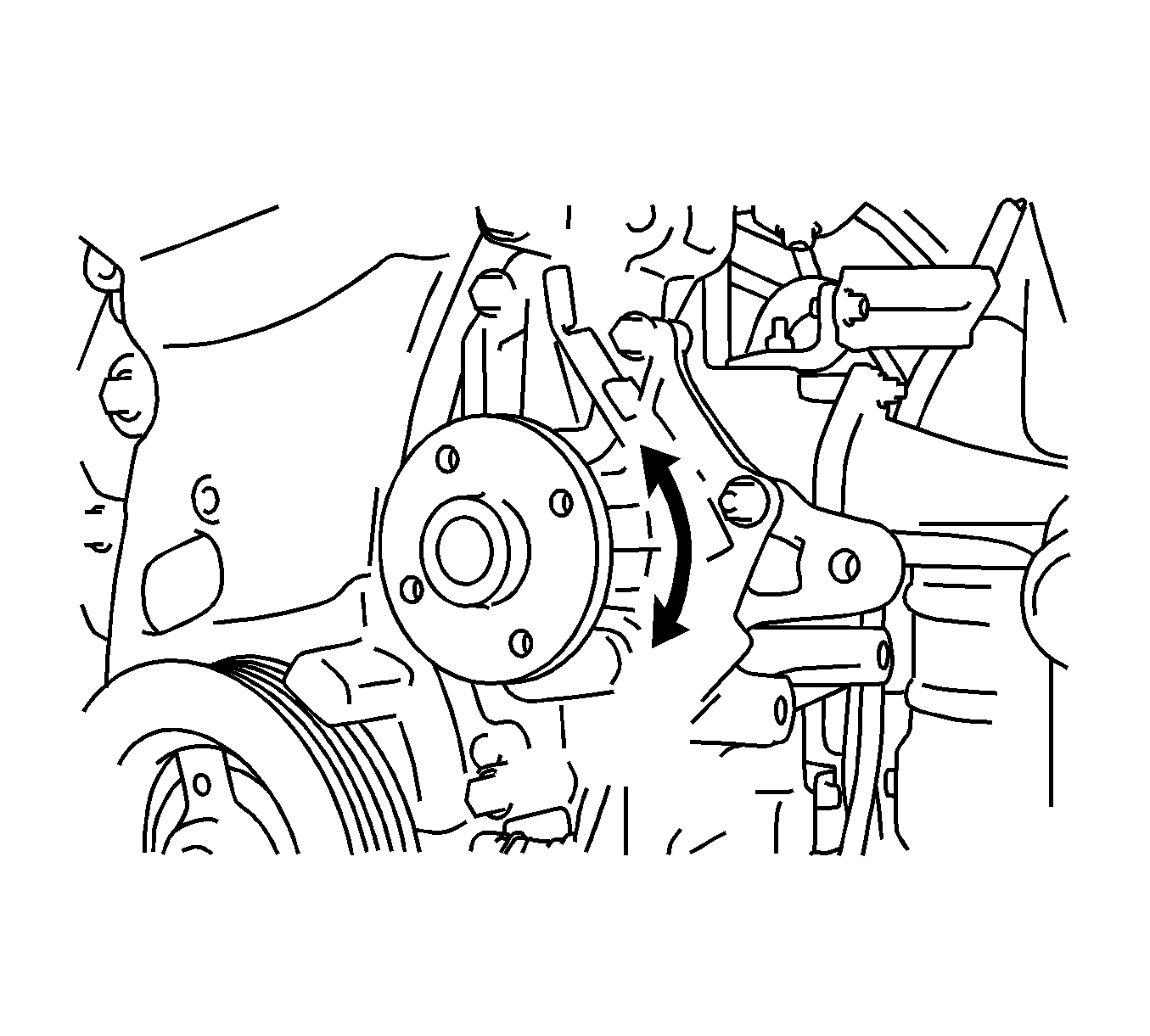
If it does not move smoothly, replace the water pump assembly.
Removal Procedure
- Disconnect cable from negative battery terminal. Refer to Battery Negative Cable Disconnection and Connection.
- Remove the left engine under cover.
- Remove the right engine under cover.
- Drain the engine coolant. Refer to Cooling System Draining and Filling.
- Separate the radiator reserve tank assembly. Refer to Radiator Surge Tank Replacement.
- Remove the v-ribbed belt. Refer to Drive Belt Replacement.
- Remove the generator assembly. Refer to Generator Replacement.
- Remove the right engine mounting insulator subassembly. Refer to Engine Mount Replacement.
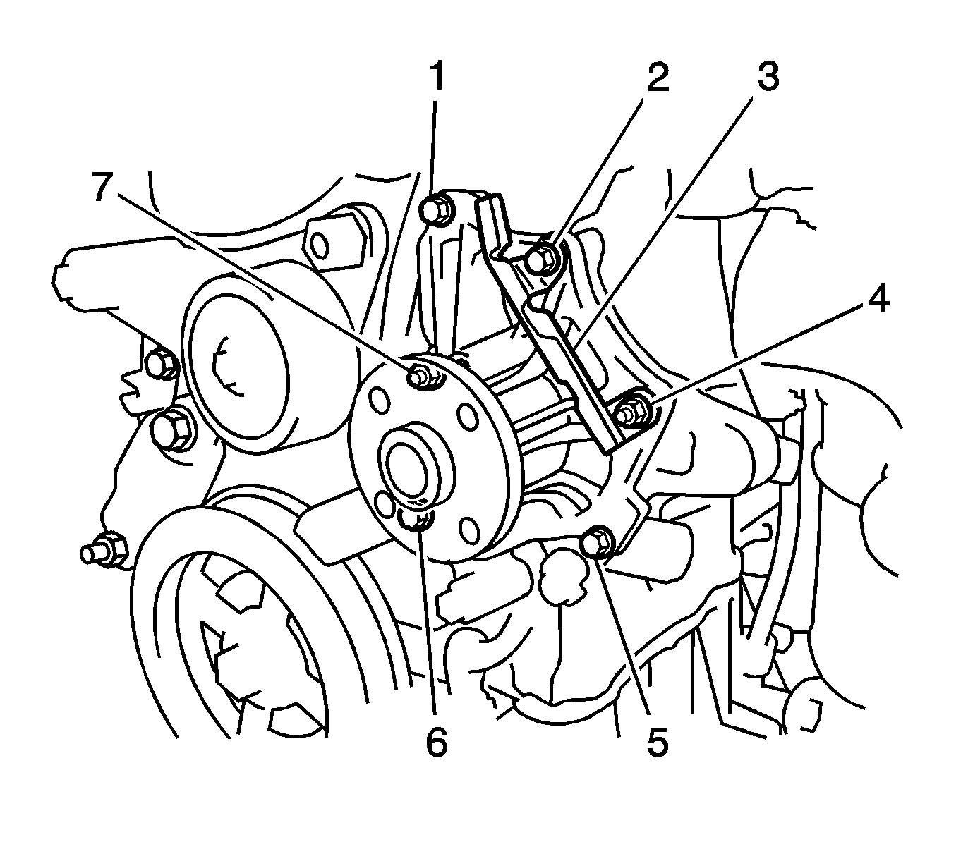
- Using EN 46104 , remove the 4 bolts (1, 2, 3, 4) and water pump pulley.
- Remove the clamp (1) of the crankshaft position sensor from the water pump.
- Disconnect the wire of the crankshaft position sensor from the clamp bracket.
- Remove the 4 bolts (1,2, 5, 6), 2 nuts (4, 7) and the clamp bracket.
- Using a screwdriver, pry between the water pump and cylinder block, and then remove the water pump.
Warning: Refer to Battery Disconnect Warning in the Preface section.
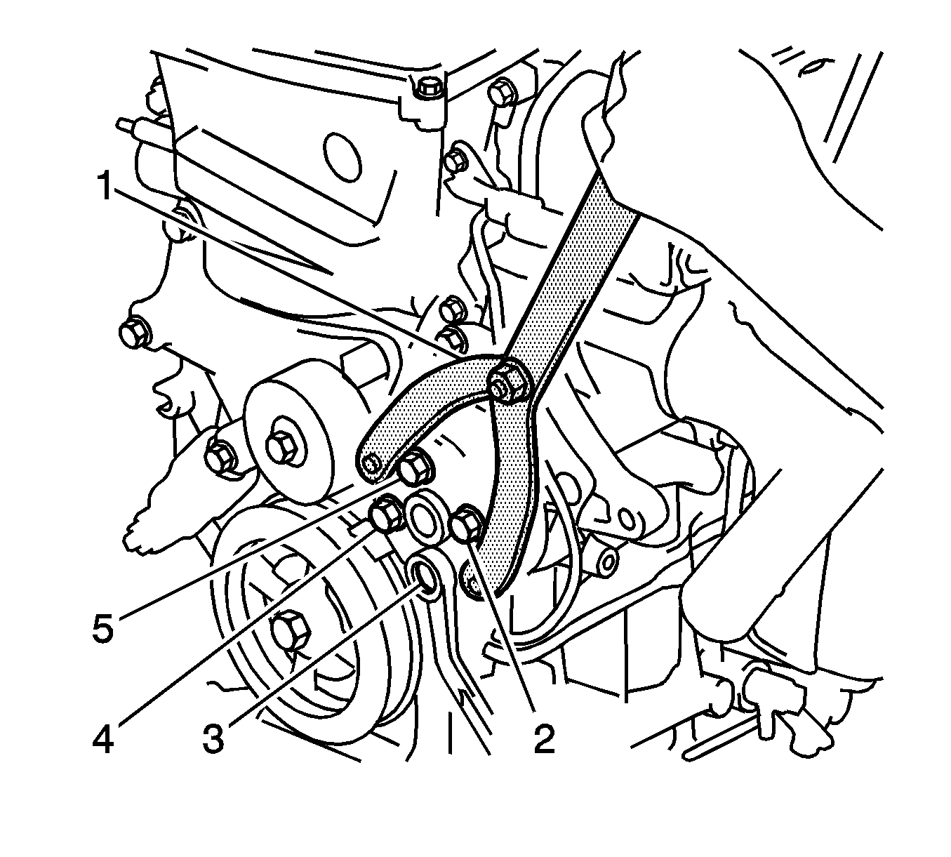
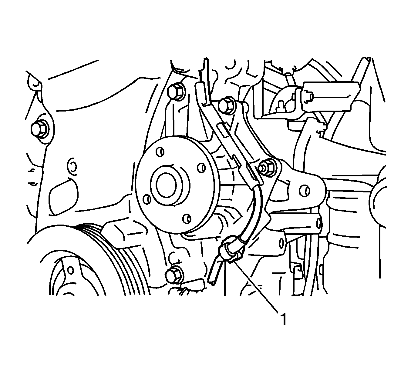
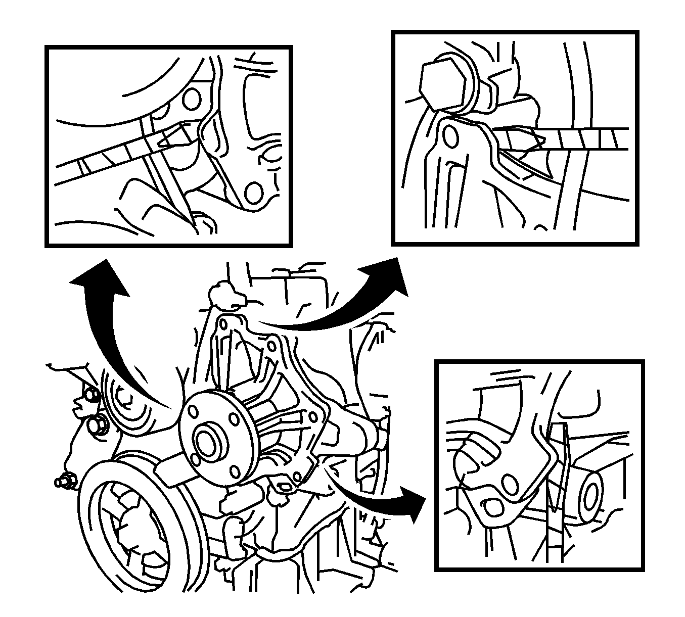
Note: Tape the screwdriver tip before use.
Installation Procedure
- Remove any old gasket sealer material from the contact surface.
- Apply a continuous line of Three Bond 1217B (1) or equivalent, GM part number 12378521 (Canadian part number 88901148).
- Install the water pump and the clamp bracket with the 4 bolts (1, 2, 5, 6) and the 2 nuts (4, 7). Tighten the bolts to 9.0 N·m (80 lb in).
- Confirm that the wire harness of the crankshaft position sensor is secured to the wire harness clamp bracket (1) through the back of the rib of the timing chain cover.
- Install the wire harness clamp.
- Install the water pump pulley with the 4 bolts (2, 3, 4, 5) and tighten to 26 N·m (19 lb ft).
- Install the right engine mounting insulator subassembly. Refer to Engine Mount Replacement.
- Install the generator assembly. Refer to Generator Replacement.
- Install the v-ribbed belt. Refer to Drive Belt Replacement.
- Install the radiator reserve tank assembly. Refer to Radiator Surge Tank Replacement.
- Connect the cable to negative battery terminal.
- Add the engine coolant. Refer to Cooling System Draining and Filling.
- Inspect for coolant leaks. Refer to Cooling System Leak Testing.
- Inspect the reservoir tank engine coolant level.
- Install the right engine under cover.
- Install the left engine under cover.
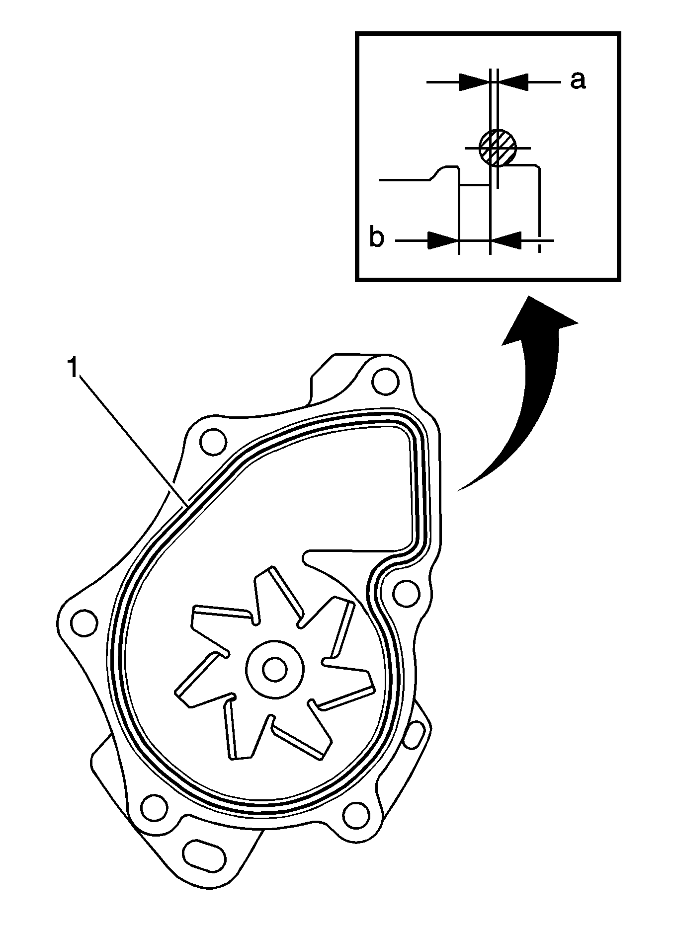
Note:
• Remove any oil from the contact surface. • The parts must be set within 3 minutes after applying sealant. Otherwise, the material must be removed and reapplied.
Specification
Standard Seal Diameter: 2.2 to 2.5 mm (0.0866 to 0.0984 in)
Caution: Refer to Fastener Caution in the Preface section.


Coolant Pump Replacement 1.8L
Inspection Procedure
- Remove the engine cover. Refer to Engine Cover Replacement.
- Remove the right engine under cover.
- Remove the v-ribbed belt. Refer to Drive Belt Replacement.
- Inspect water pump assembly.
- Turn the pulley and check that the water pump bearing moves smoothly and quietly.
- Make sure that there are no drops of coolant on the water pump housing.
- Install the v-ribbed belt. Refer to Drive Belt Replacement.
- Install the right engine under cover.
- Install the engine cover. Refer to Engine Cover Replacement.
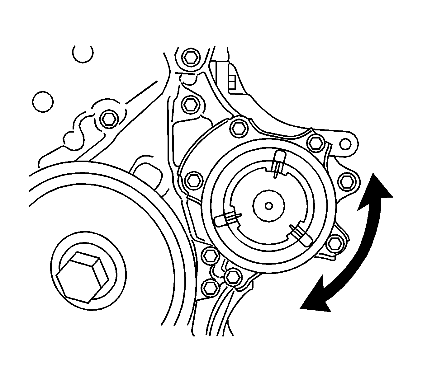
If necessary, replace the water pump assembly.
If necessary, replace the water pump assembly.
Removal Procedure
- Disconnect cable from negative battery terminal. Refer to Battery Negative Cable Disconnection and Connection
- Remove the engine cover. Refer to Engine Cover Replacement.
- Remove the right engine under cover.
- Drain the engine coolant. Refer to Cooling System Draining and Filling.
- Remove the v-ribbed belt. Refer to Drive Belt Replacement.
- Remove the generator assembly. Refer to Generator Replacement.
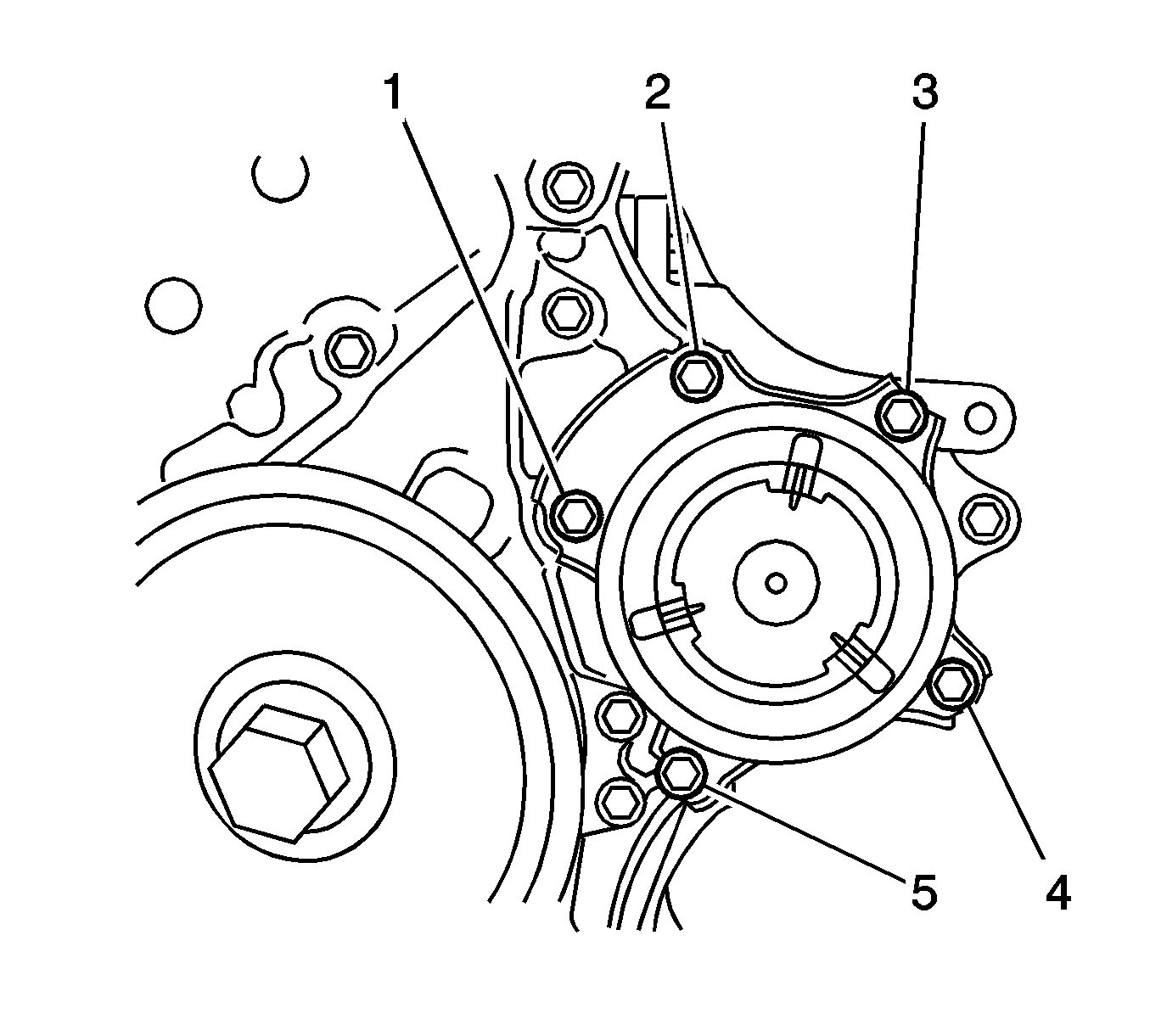
- Remove the 5 bolts (1, 2, 3, 4, 5) and water pump assembly from the timing chain cover.
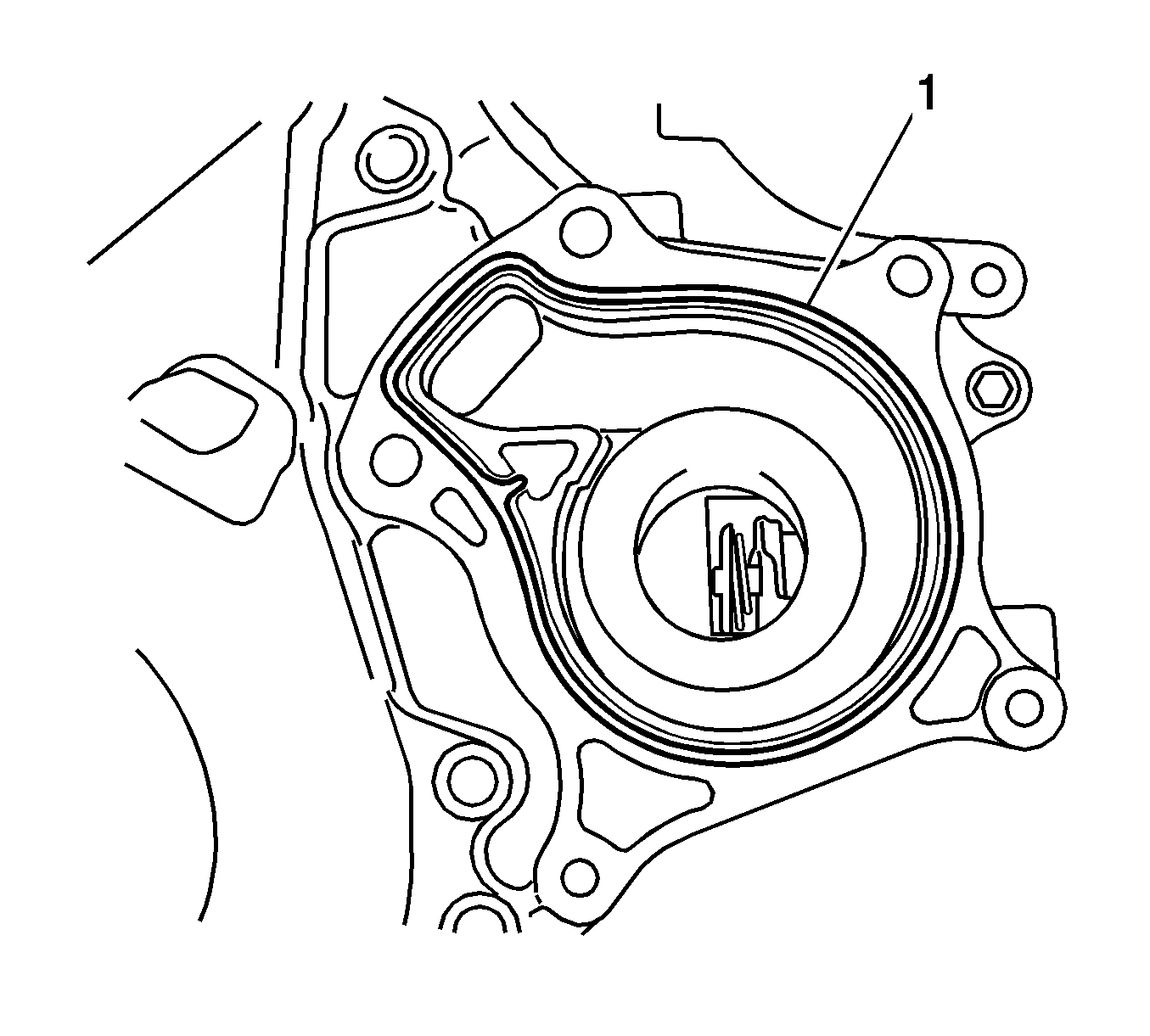
- Remove the water pump gasket (1) from the timing chain cover.
Warning: Refer to Battery Disconnect Warning in the Preface section.
Installation Procedure
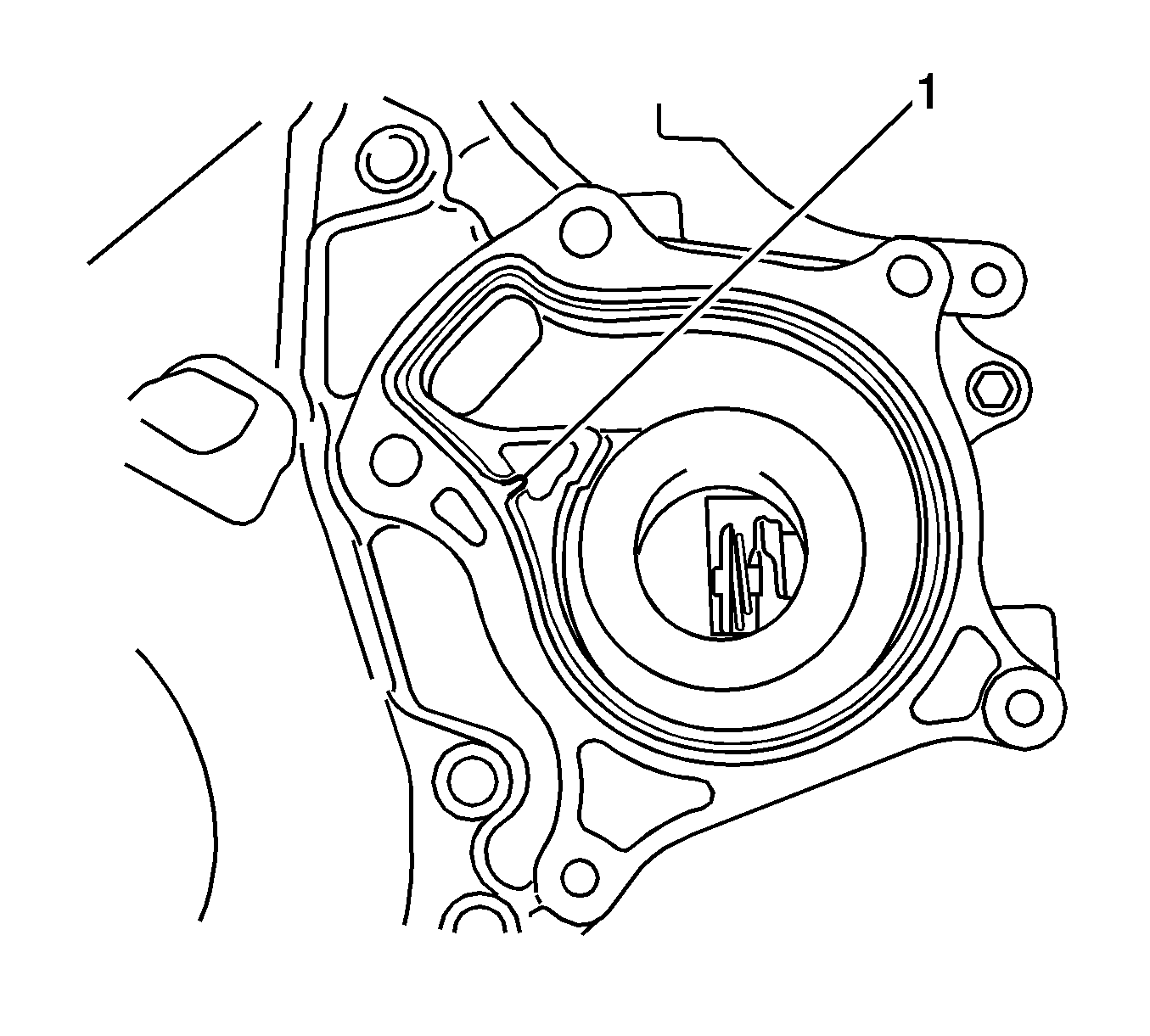
- Align the protrusion (1) of a new water pump gasket with the cutout in the timing chain cover and install the gasket to the groove of the timing chain cover.
- Install the water pump assembly to the timing chain cover with the 5 bolts (1, 2) and tighten.
- Install the generator assembly. Refer to Generator Replacement.
- Install the v-ribbed belt. Refer to Drive Belt Replacement.
- Connect the cable to negative battery terminal.
- Add the engine coolant. Refer to Cooling System Draining and Filling.
- Inspect for coolant leaks. Refer to Cooling System Leak Testing
- Inspect the reservoir tank engine coolant level.
- Install the right engine under cover.
- Install the engine cover. Refer to Engine Cover Replacement.
Note: Be sure to clean the contact surfaces.
Caution: Refer to Fastener Caution in the Preface section.
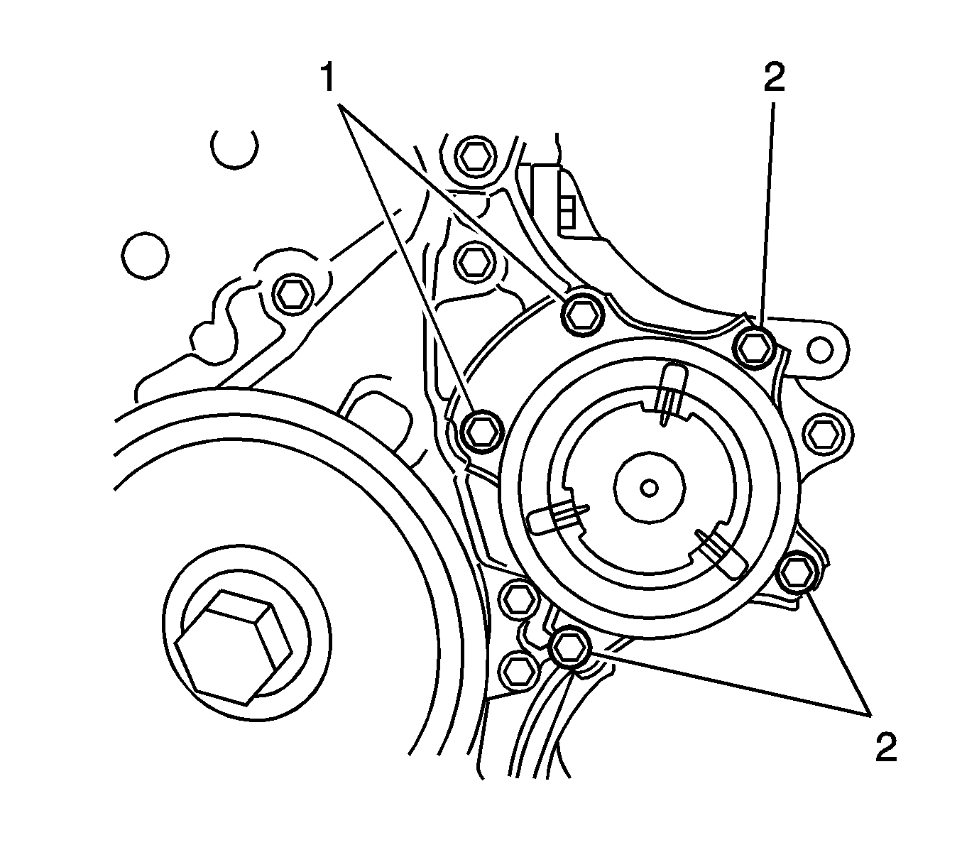
| • | Bolt 1 to 26 N·m (19 lb ft). |
| • | Bolt 2 to 24 N·m (18 lb ft). |
