Special Tools
KM-527-A
Adjuster
Removal Procedure
- Remove battery tray. Refer to
Battery Tray Replacement
.

Important: Do not remove the bolt.
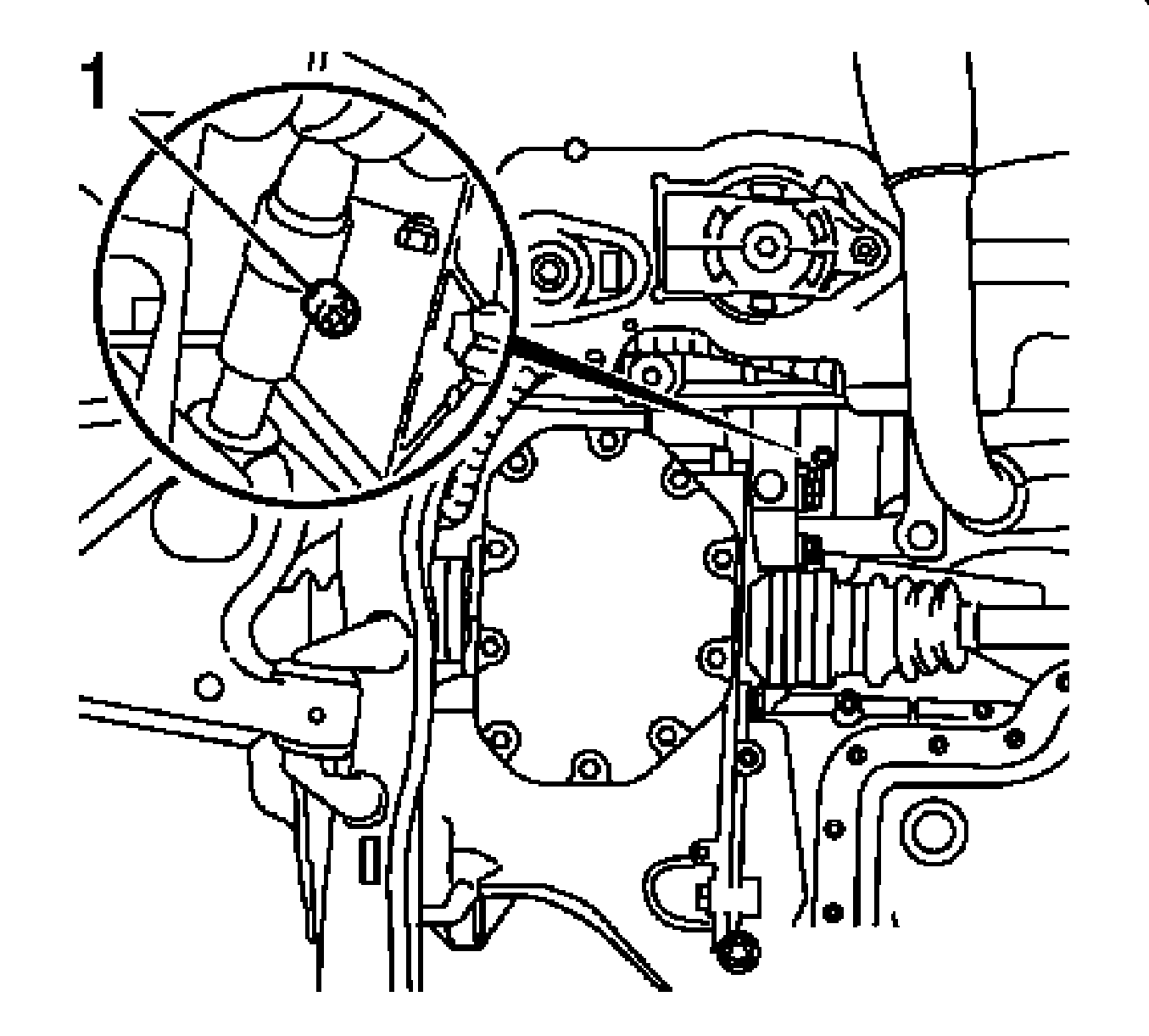
- Release the selector lever link.
Loosen the bolt (1) for the relay point clamp.
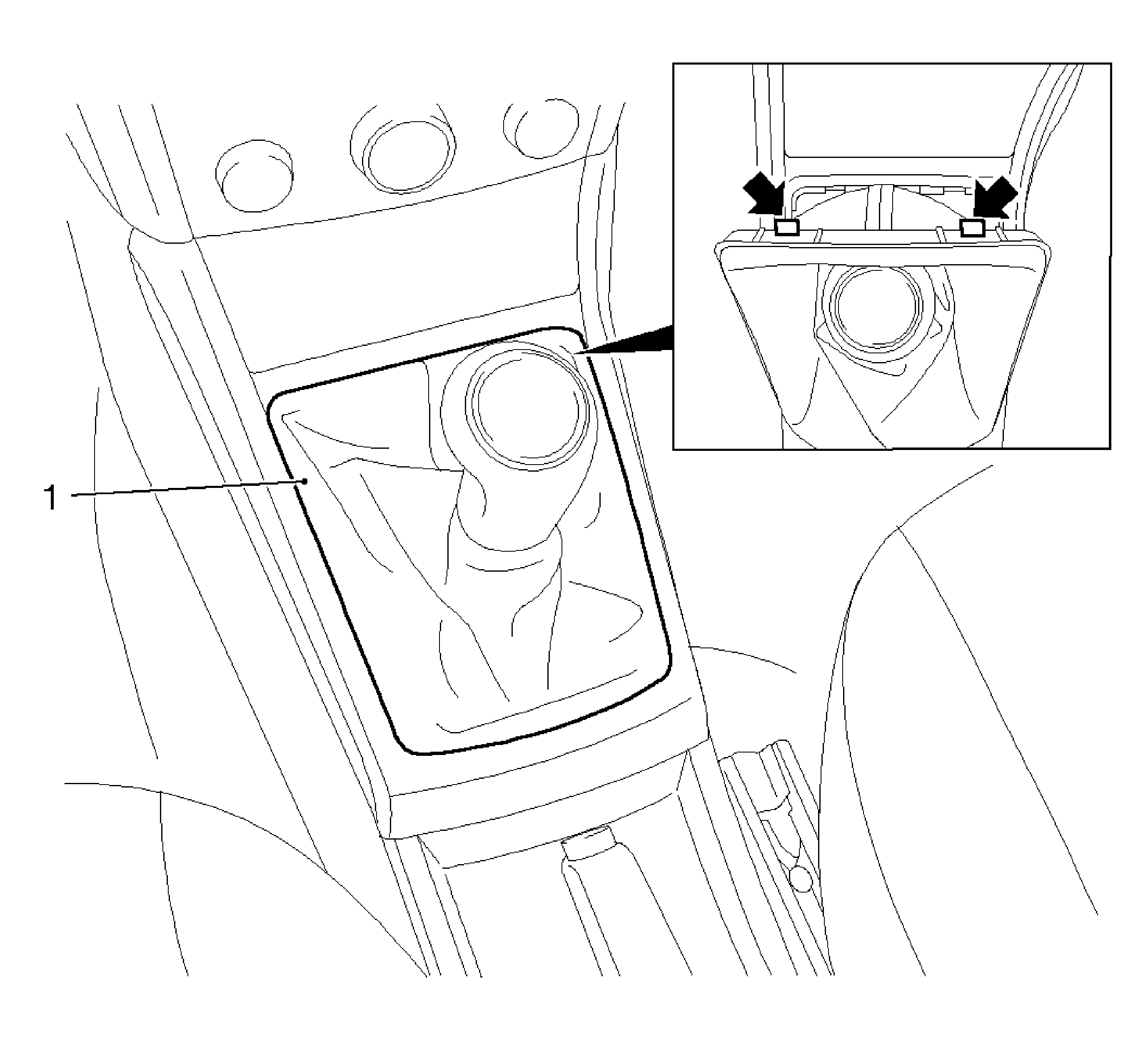
- Detach the over of the transmission control lever (1).
| • | Release the cover of the transmission control lever at the front (arrows) from the front floor console. |
| • | Prop up the cover of the transmission control lever with the cover frame. |

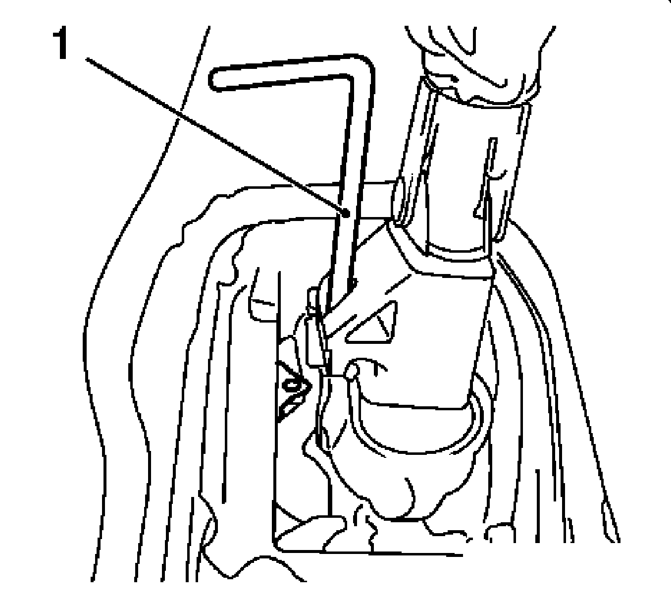
- Lock the transmission control lever in adjustment position.
| • | Push the transmission control lever to the left. |
| • | Lock the transmission control lever and transmission control lever housing with the
KM-527-A
(1). |

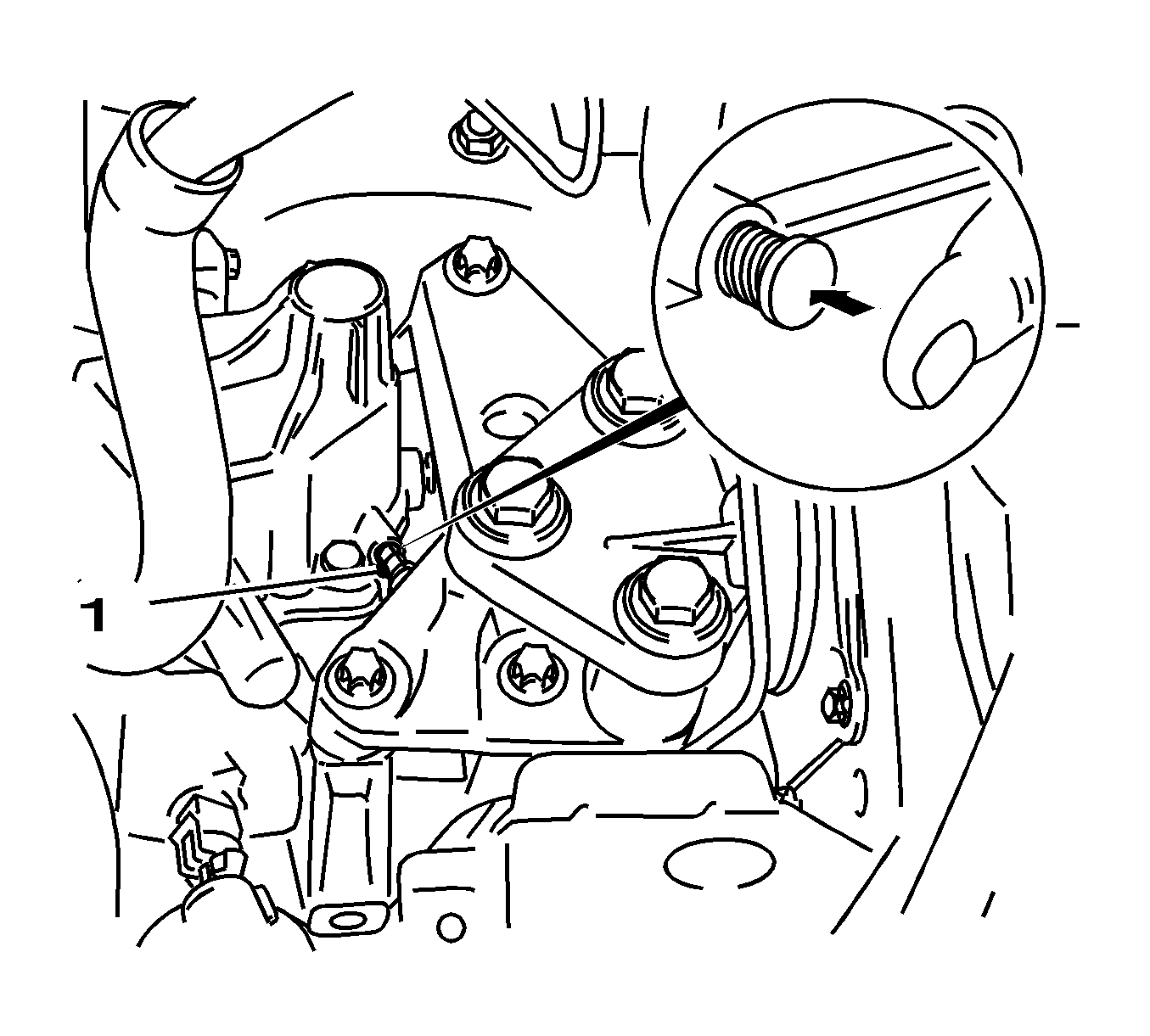
- Lock the selector lever link shaft in the transmission cover.
| • | Turn the selector lever link counterclockwise. |
| • | Direction of the 3rd gear |
| • | Engage the locking pin (1) in the adjusting bore in the transmission cover (arrow). |

Installation Procedure
Notice: Refer to Fastener Notice in the Preface section.
Important: Do not change the position of the gearshift rod.
- Install the selector lever link.
Tighten
Tighten the bolt (1) to 12 N·m (106 lb in) plus 180-225 degrees.

- Release the transmission control lever lock.
Detach the
KM-527-A
(1).

- Attach the cover of the transmission control lever (1).
| • | Insert the cover of the transmission control lever at the rear in the front floor console. |
| • | Clip the cover of the transmission control lever into the front floor console at the front (arrows). |

Important: The locking pin in the adjusting bore hole releases automatically when first shifted in "R" direction, if necessary release the locking pin by hand.
- Release the locking pin in the transmission cover.
- Inspect ease of gear shifting.
- Install battery tray . Refer to
Battery Tray Replacement
.
- For programming procedures, refer to
Control Module References
.


