Timing Belt Inspection and Adjustment Inspection
Special Tools
| • | MK-6340 /KM-6340-Left/KM-6340-Right Locking Tool |
| • | MK-6628 Locking Tool |
Removal Procedure
- Detach the front toothed belt cover (upper). Refer to Timing Belt Upper Front Cover Installation.
- Raise the vehicle by its full height.
- Remove the lower engine cover and the right engine splash guard.
- Set the engine to "TDC".
- Lower the vehicle by its full height.
- Prepare the right half of MK-6340 for use on the U 18 XER engine.
- Insert MK-6340 into the camshaft timing gears.
- Remove the camshaft cover. Refer to Camshaft Cover Installation.
- Insert MK-6628 (1) into the camshafts.
- Raise the vehicle by its full height.
- Check the position of crankshaft.
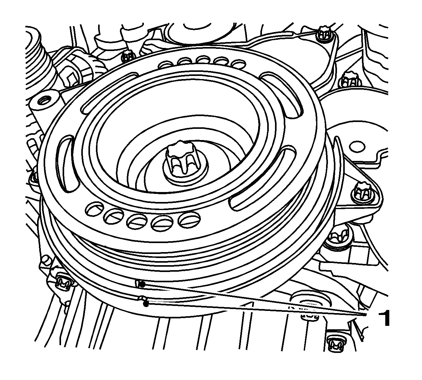
Set the torsional vibration balancer in the direction of the engine rotation to "1st cylinder TDC" (mark 1).
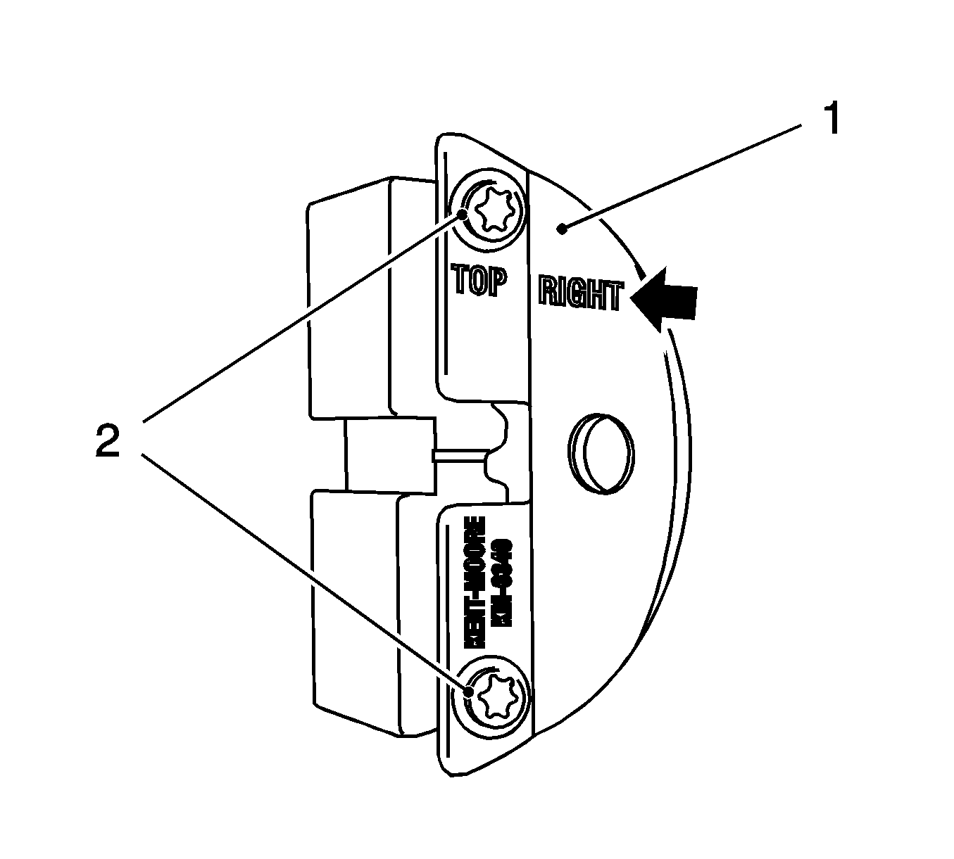
Note: Recognizable from the lettering "Right" (arrow)
| • | Detach the front panel (1) from MK-6340 KM-6340-Right. |
| • | Unscrew the 2 bolts (2). |
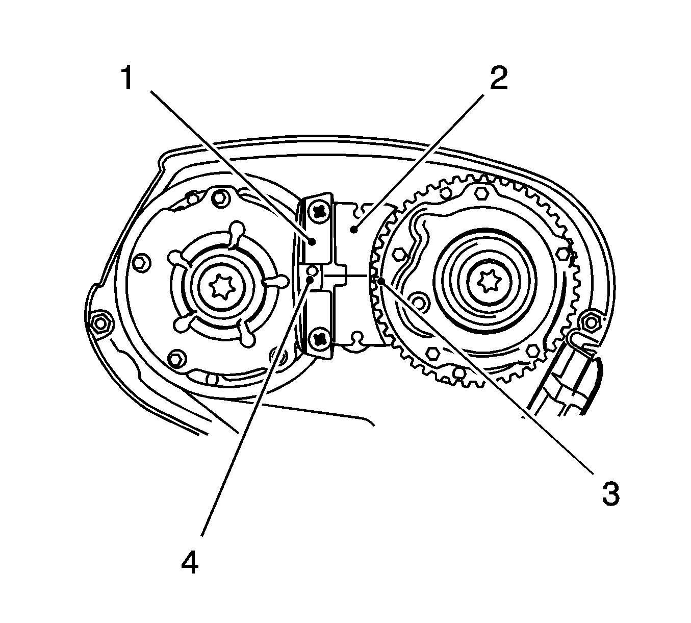
Note: The spot-type marking (4) on the intake camshaft adjuster does not correspond to the groove of MK-6340 KM-6340-Left during this process but must be somewhat above as shown.
The spot type marking (3) on the exhaust camshaft adjuster must correspond to the groove on MK-6340 KM-6340-Right.Insert MK-6340 KM-6340-Left (1) and MK-6340 KM-6340-Right (2) in the camshaft adjuster as shown.
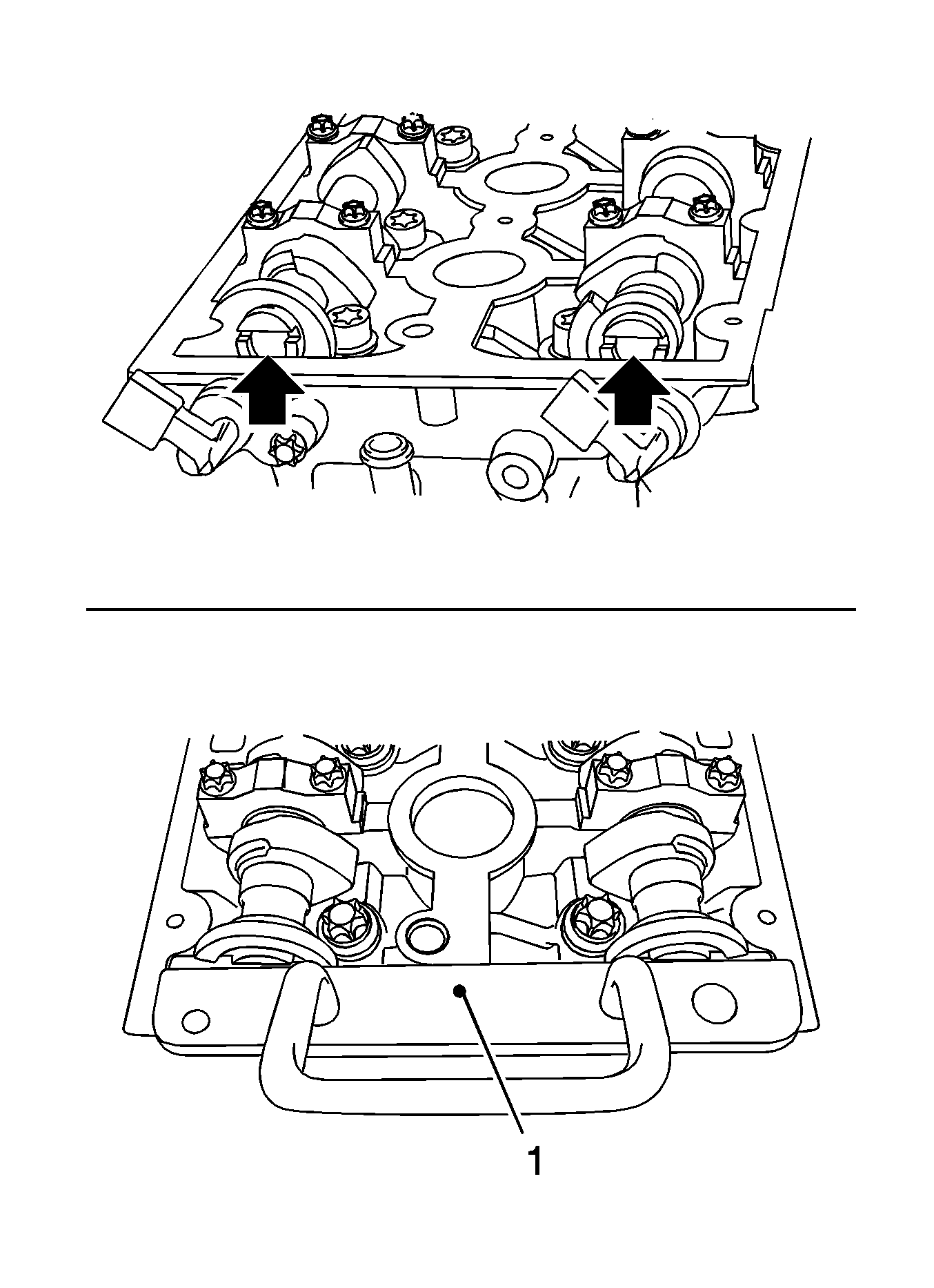
Note: If MK-6628 cannot be inserted, the timing must be set.
Align the camshafts horizontally by the hexagon (arrows) until MK-6628 can be inserted in both camshafts.
Marking on torsional vibration damper must align with the marking on the lower part of the toothed belt cover.
Installation Procedure
- Install the lower engine cover and the right engine splash guard.
- Lower the vehicle by its full height.
- Remove MK-6628
- Install the camshaft cover. Refer to Camshaft Cover Installation.
- Remove MK-6340 .
- Attach the bracket.
- Attach front toothed belt cover (upper). Refer to Timing Belt Upper Front Cover Installation.
Caution: Refer to Fastener Caution in the Preface section.
Tighten
Tighten the 2 bolts to 8 N·m (71 lb in).
Timing Belt Inspection and Adjustment Adjustment
Special Tools
| • | KM-6009 Remover/Installer |
| • | KM-6333 Fixing Rod |
| • | MK-6340 Locking Tool |
| • | KM-6349 Fixing Rod |
| • | KM-6625 Flywheel Locking Device |
| • | MK-6628 Locking Tool |
Removal Procedure
- Open the hood.
- Disconnect the battery.
- Remove the air cleaner assembly. Refer to Air Cleaner Assembly Replacement.
- Remove the drive belt cover upper section.
- Raise the vehicle by its full height.
- Remove the drive belt tensioner. Refer to Drive Belt Tensioner Replacement.
- Lower the vehicle by its full height.
- Detach the engine management wiring harness from the intake manifold, cylinder head cover.
- Remove the cover of the ignition module.
- Remove the ignition module.
- Detach the engine management wiring harness from the intake manifold, cylinder head cover.
- Remove the engine venting pipe.
- Remove the cylinder head cover.
- Prepare the right half of MK-6340 for use on the U 18 XER engine.
- Insert MK-6340 into the camshaft timing gears.
- Stop the drive belt tensioner.
- Mark the drive belt direction of rotation.
- Raise the vehicle by its full height.
- Block the crankshaft.
- Remove the torsional vibration damper (1).
- Remove the front drive belt cover (bottom) (3).
- Remove the drive belt guide roller.
- Clean the thread, drive belt guide roller.
- Lower the vehicle by its full height.
- Remove the drive belt.
- Raise the vehicle by its full height.
- Remove KM-6625 .
- Turn the crankshaft 60 degrees against the direction of engine rotation.
- Lower the vehicle by its full height.
- Place the collecting basin underneath.
- Unscrew the closure bolt, exhaust camshaft adjuster.
- Unscrew the intake camshaft closure bolt.
- Loosen the exhaust camshaft adjuster.
- Loosen the intake camshaft adjuster.
- Insert MK-6628 (1) into the camshafts.
Warning: Refer to Battery Disconnect Warning in the Preface section.
| • | Detach the ground connection from ground terminal. |
| • | Loosen the nut. |
Remove the 2 bolts.
Release 2x from bracket.
Release the cover in the direction of the arrow.
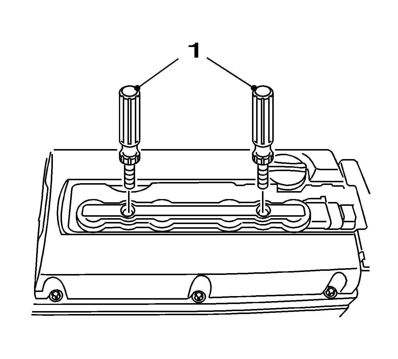
| • | Disconnect the wiring harness connector. |
| • | Unscrew the 2 bolts. |
| • | Screw in 2 KM-6009 . |
| • | Take out the ignition module. |
| • | Remove the wiring trough. |
| • | Release 3x. |
| • | Release the wiring harness from the guide. |
Disconnect the 2 quick-release fittings.
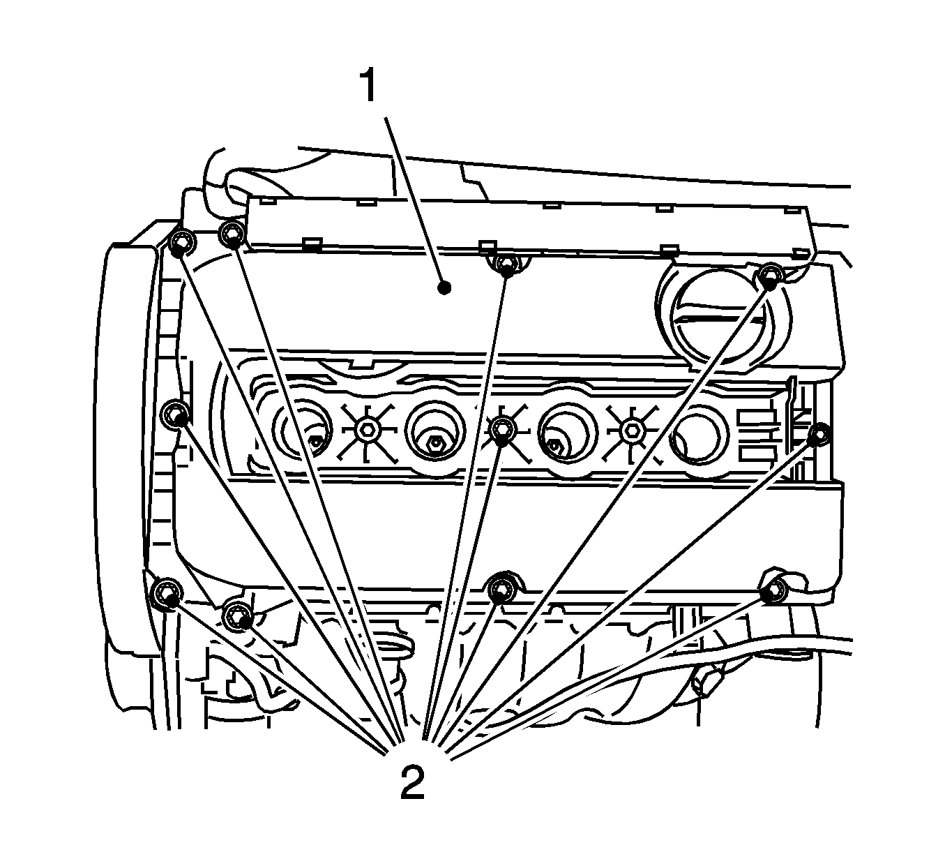
Remove the 11 bolts.

Note: Recognizable from the lettering "Right" (arrow).
| • | Detach the front panel (1) from MK-6340 . |
| • | Unscrew the 2 bolts (2). |

Note: The spot-type marking (4) on the intake camshaft adjuster does not correspond to the groove of MK-6340 during this process but must be somewhat above as shown.
The spot type marking (3) on the exhaust camshaft adjuster must correspond to the groove on MK-6340 .Insert MK-6340 (1, 2) in the camshaft adjuster as shown.
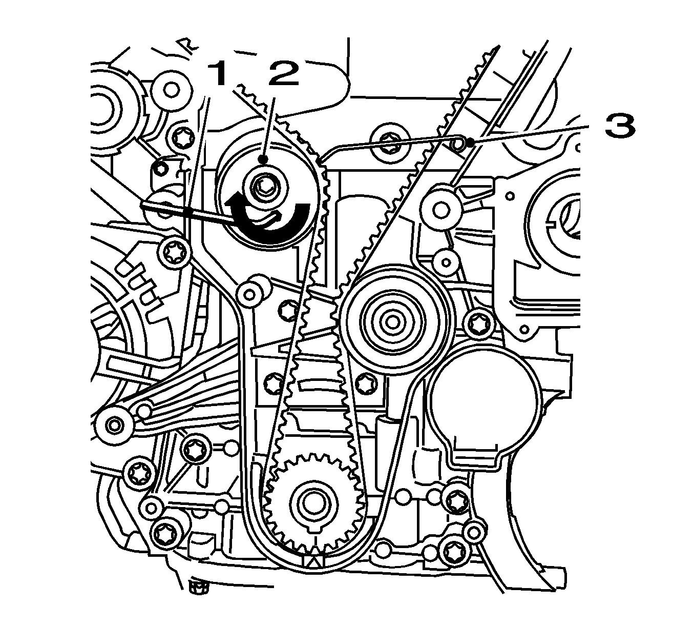
Apply tension to the drive belt tensioner (2) in the direction of the arrow, using an Allen key (1). Fix using KM-6333 (3).
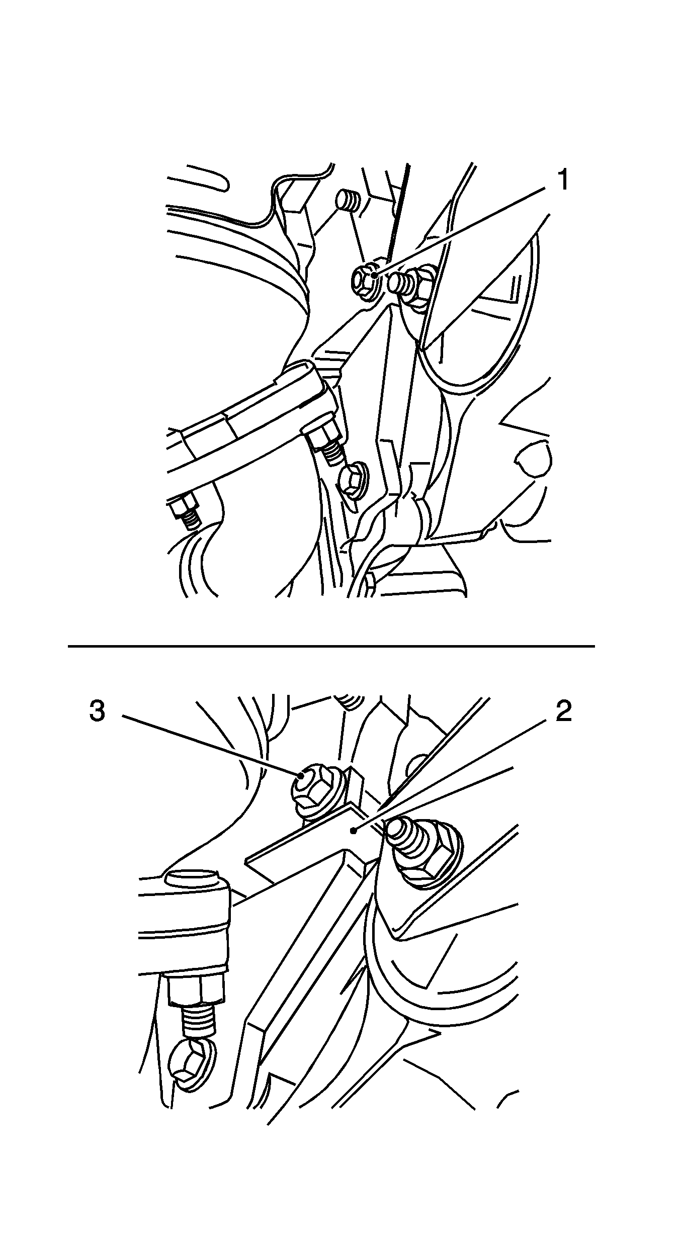
| • | Attach KM-6625 . |
| • | Detach the screwed connection (1). |
| • | Insert KM-6625 (2). |
| • | Tighten the screwed connection (3). |
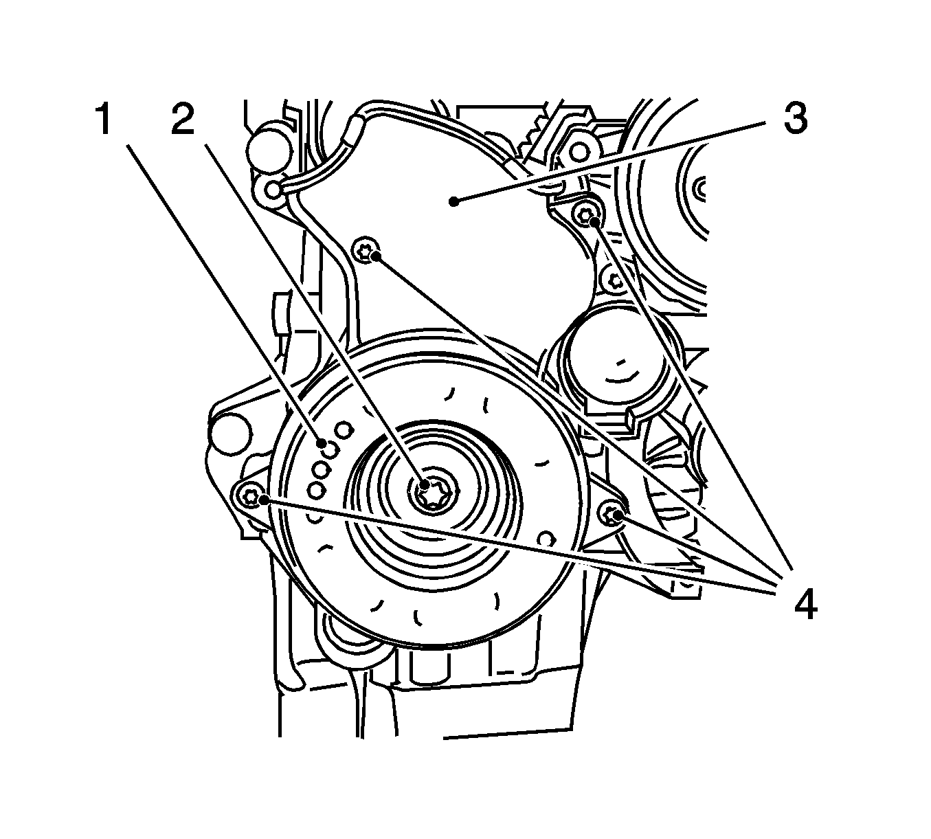
Remove the bolt (2).
Remove the 4 bolts (4).
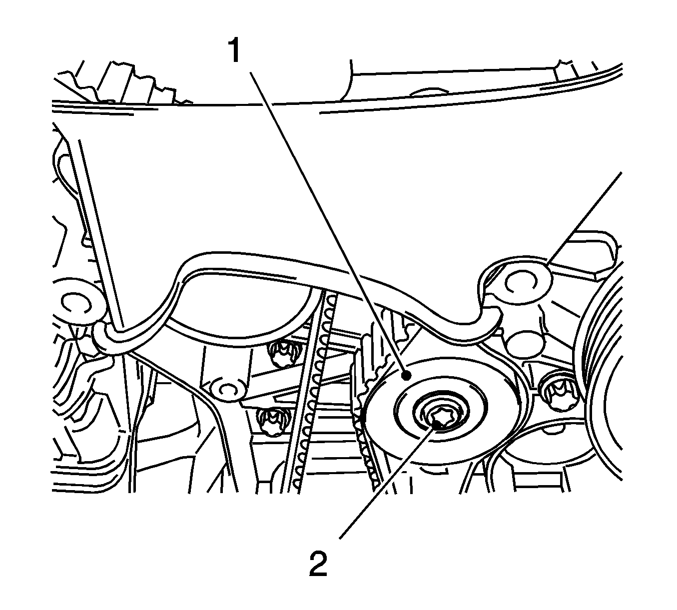
Remove the bolt.
Detach the screwed connection.
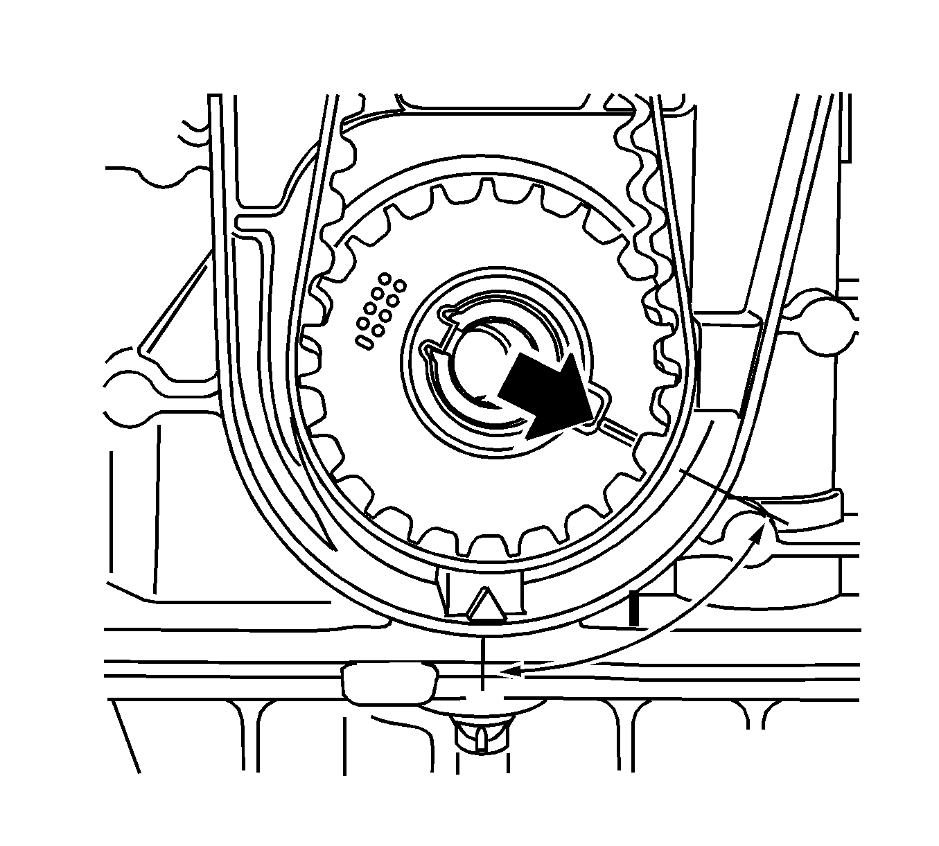
Counterhold at camshaft hexagon.
Counterhold at camshaft hexagon.

Note: If MK-6628 cannot be inserted, the timing must be set.
Align the camshafts horizontally by the hexagon (arrows) until MK-6628 can be inserted in both camshafts.
Installation Procedure
- Tighten the exhaust camshaft adjuster.
- Counterhold at camshaft hexagon.
- Tighten the intake camshaft adjuster.
- Counterhold at camshaft hexagon.
- Tighten the exhaust camshaft adjuster closure bolt.
- Replace the seal ring.
- Unscrew the intake camshaft closure bolt.
- Remove MK-6628 .
- Raise the vehicle by its full height.
- Set the crankshaft to cylinder number 1 ignition TDC (1).
- Block the crankshaft.
- Lower the vehicle by its full height.
- Insert the drive belt.
- Fit the drive belt guide roller.
- Release the tension on the drive belt tensioner.
- Raise the vehicle by its full height.
- Install the drive belt cover lower section.
- Install the torsional vibration damper.
- Remove KM-6625 .
- Lower the vehicle by its full height.
- Remove MK-6340 .
- Check the position of the camshaft sprockets.
- Check camshaft positions.
- Raise the vehicle by its full height.
- Check crankshaft position.
- Clean the thread of the bolt, drive belt tensioner.
- Install the drive belt tensioner.
- Insert the drive belt.
- Install the lower engine compartment cover or the right engine splash guard.
- Lower the vehicle by its full height.
- Remove MK-6628 .
- Install the cylinder head cover.
- Install the engine venting pipe.
- Attach the engine management wiring harness to the intake manifold.
- Install the ignition module.
- Install the cover of the ignition module.
- Attach the engine management wiring harness to the intake manifold.
- Remove MK-6340 .
- Install the front drive belt cover (top).
- Install the air cleaner assembly. Refer to Air Cleaner Assembly Replacement.
- Connect the battery.
- For programming procedures, refer to Control Module References.
- Close the hood.
Caution: Refer to Fastener Caution in the Preface section.
Tighten
Tighten the exhaust camshaft adjuster to 65 N·m (48 lb ft) plus 125 degrees plus 15 degrees.
Tighten
Tighten the intake camshaft adjuster to 65 N·m (48 lb ft) plus 125 degrees plus 15 degrees.
Tighten
Tighten the exhaust camshaft adjuster closure bolt to 30 N·m (22 lb ft).
Replace the seal ring.
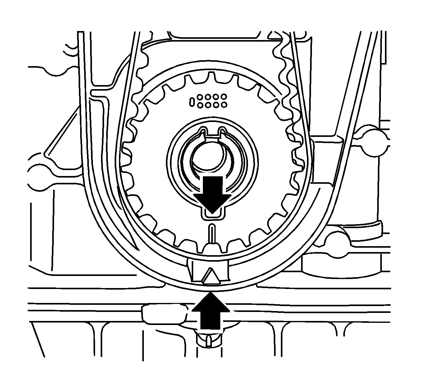
Marking, drive belt drive gear and oil pump housing must align.
| • | Insert KM-6625 . |
| • | Install the bolted connection. |
Note: Use the assembly tool.
Tighten
Tighten the new bolt to 25 N·m (18 lb ft).
| • | Apply preliminary tension clockwise to the drive belt tension roller. |
| • | Remove KM-6333 . |
Tighten
Tighten the 4 bolts to 6 N·m (53 lb in).
Note: New bolt must be coated with screw locking compound (red).
Tighten
Tighten the new bolt to 95 N·m (70 lb ft) plus 30 degrees plus 15 degrees.
| • | Detach the screwed connection. |
| • | Tighten the bolted connection. |
| • | Use new nuts. |
| Note: Note marking, camshaft sprockets. |
| • | Turn the crankshaft 720 degrees in the direction of engine rotation by the bolt on the torsional vibration damper. |
| • | Insert MK-6340 into camshaft timing gears. |
Insert MK-6628 in the camshafts, align the camshafts by hexagon until MK-6628 can be inserted in both camshafts, marking on torsional vibration damper must align with marking on lower part of drive belt cover.
Tighten
Tighten the new bolt to 50 N·m (37 lb ft).
| • | Observe the direction of rotation. |
| • | Apply tension to the tensioner at projection counterclockwise in the direction of the arrow. |
| • | Remove KM-6349 . |
Replace the cylinder head gasket.
Tighten
Tighten the 11 bolts to 8 N·m (71 lb in).
Connect the 2 quick-release fittings.
| • | Attach the wiring trough. |
| • | Clip on 3x. |
| • | Clip the wiring harness into the guide. |
| • | Insert the ignition module. |
| • | Unscrew the 2 KM-6009 . |
| • | Tighten the 2 bolts. |
Tighten
Tighten the 2 bolts to 8 N·m (71 lb in).
| • | Fix the wiring harness plug. |
Clip 2x in bracket.
Attach the bracket.
Tighten
Tighten the 2 bolts to 5 N·m (44 lb in).
Tighten
Tighten the 2 bolts to 6 N·m (53 lb in).
| • | Attach the air intake hose to the throttle valve module. |
| • | Attach the resonator air intake housing to the air cleaner housing. |
| • | Connect the mass air flow meter wiring harness plug. |
| • | Fasten the clamp. |
Attach the ground connection to the ground terminal.
Tighten
Tighten the nut to 5 N·m (44 lb in).
