Special Tools
KM-6384 Assembly Clamp
Removal Procedure
- Remove the front wheel.
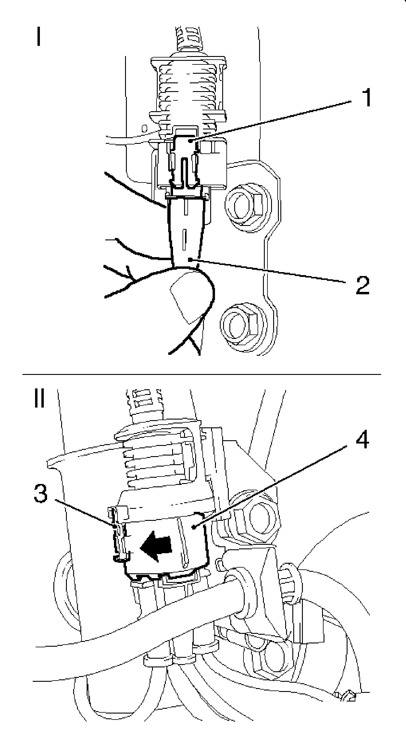
- Detach the wiring harness from the spring strut.
| • | In vehicles without brake pad wear indicator (I): |
| - | Push lock mechanism (1) downward. |
| - | Disconnect the wheel sensor wiring harness (2). |
| • | In vehicles with brake pad wear indicator (II): |
| - | Slide the primary lock mechanism (3) downward. |
| - | Twist the secondary lock mechanism (4) in direction of arrow. |
| - | Disconnect the brake pad wear indicator wiring harness plug from the wiring harness. |
| - | Disconnect the wheel sensor wiring harness plug from the wiring harness. |
| • | Clip in spring strut wiring harness. |
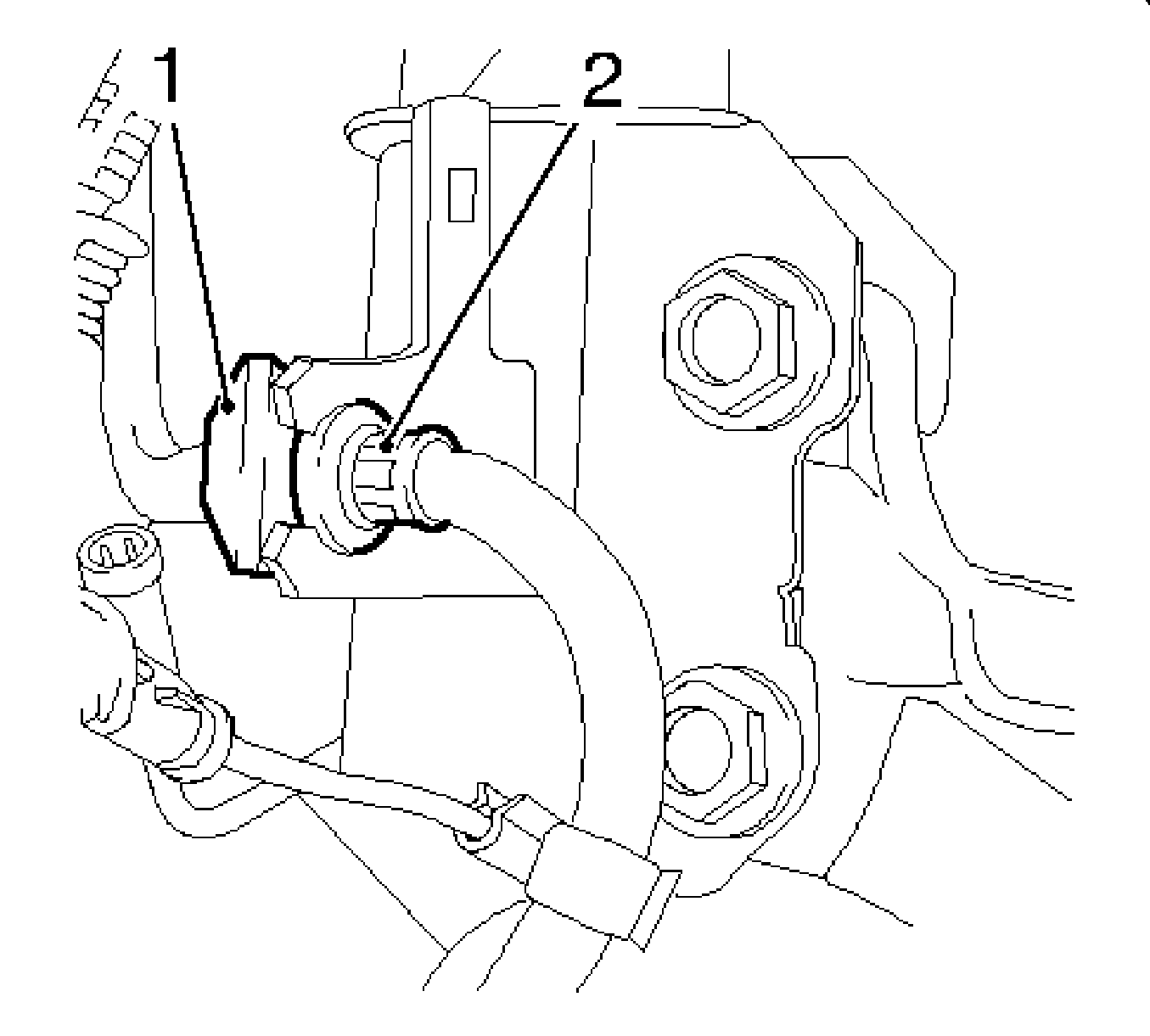
- Remove the brake hose from the spring strut support tube.
| • | Remove the retaining clip (1). |
| • | Pull the brake hose (2) out of bracket. |
- Remove the swing arm (1) from spring strut support tube.
Counterhold at the two flattened areas with open-ended wrench.
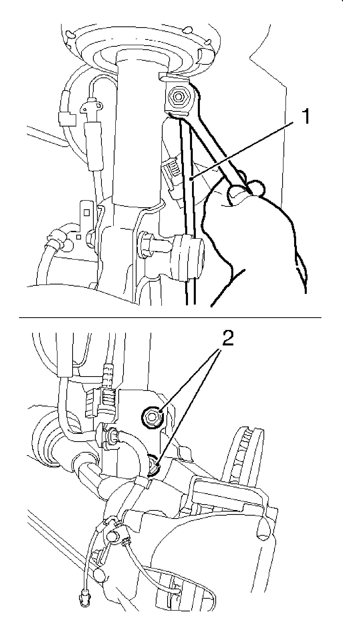
- Remove the steering knuckle from the string strut.
| • | Remove the 2 bolted connections (2). |
| • | Tilt the steering knuckle towards the outside. |
Note:
| • | Before removing retaining ring, hold spring strut. |
| • | The retaining ring cannot be removed without being destroyed and must be replaced during installation. |
- Remove the retaining ring (1) with suitable tool.
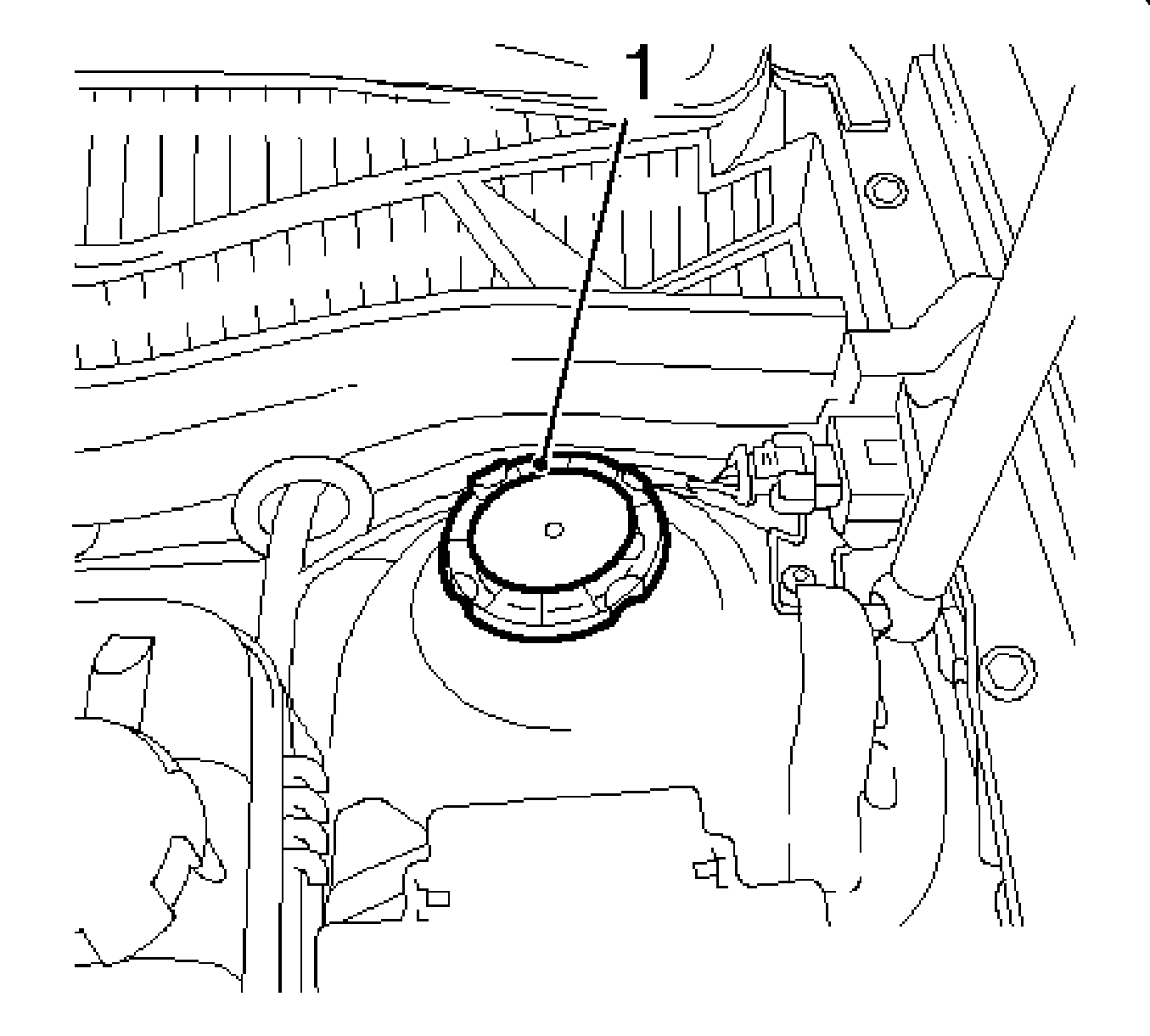
- Remove the spring strut.
Installation Procedure
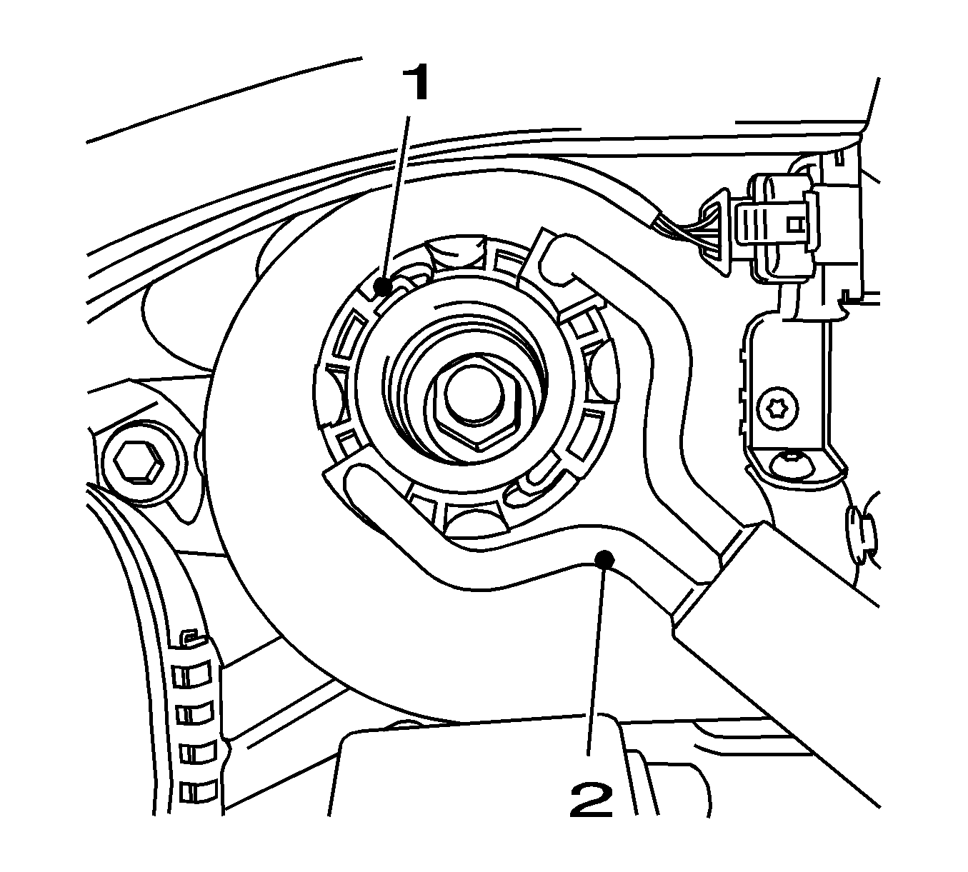
- Install the spring strut to wheel housing.
| • | Replace the spring strut in wheel housing. |
| • | Install the new retaining ring (1) with the
KM-6384 (2). |
| • | Install both halves of retaining ring by hand. |
| • | Compress the halves of retaining ring together with
KM-6384 . |
Note: Insert the bolts from front. Tightening to torque does not take place until camber has been adjusted.
- Install the spring strut to the steering knuckle.
| • | Insert 2 new screwed joints |
Caution: Refer to Fastener Caution in the Preface section.
- Install the swing arm to the spring strut support tube.
Tighten
Tighten to 55 N·m (41 lb ft).
| • | Counterhold at the two flattened areas with open-ended wrench. |
Note: Pay attention to correct hose routing.
- Install the brake hose to the spring strut support tube bracket.
| • | Insert the brake hose in the bracket. |
| • | Secure the brake hose using the retaining clip. |
- Connect the wiring harness to the spring strut.
| • | Clip in the wiring harness to the spring strut |
| • | In vehicles without brake pad wear indicator: |
| - | Connect the wheel sensor wiring harness. |
| - | Slide the lock mechanism upward. |
| • | In vehicles with brake pad wear indicator: |
| - | Connect the brake pad wear indicator wiring harness plug to the wiring harness. |
| - | Connect the wheel sensor wiring harness plug to the wiring harness. |
| - | Twist the secondary lock mechanism (4) in direction of arrow. |
| - | Slide the primary lock mechanism (3) upward. |
- Install the front wheel.
Tighten
Tighten to 110 N·m (81 lb ft).
- Inspect the camber. Refer to
Alignment Checking.
- Adjust the chamber. Refer to
Front Camber Adjustment.
- Tighten the 2 screwed joint, spring strut support tube to steering knuckle, in 3 stages.
Tighten
| • | Tighten the 2 bolted connections to 50 N·m (37 lb ft). |
| • | Tighten the 2 new screwed joints to 85 N·m 67 lb ft). |
| • | Tighten the 2 new screw connections to 75 degrees plus 15 degrees. |


