- Remove the casing of the steering column support tube at the top.
| • | Remove 2 from the instrument panel. |
- Remove the casing of the steering column support tube at the bottom.
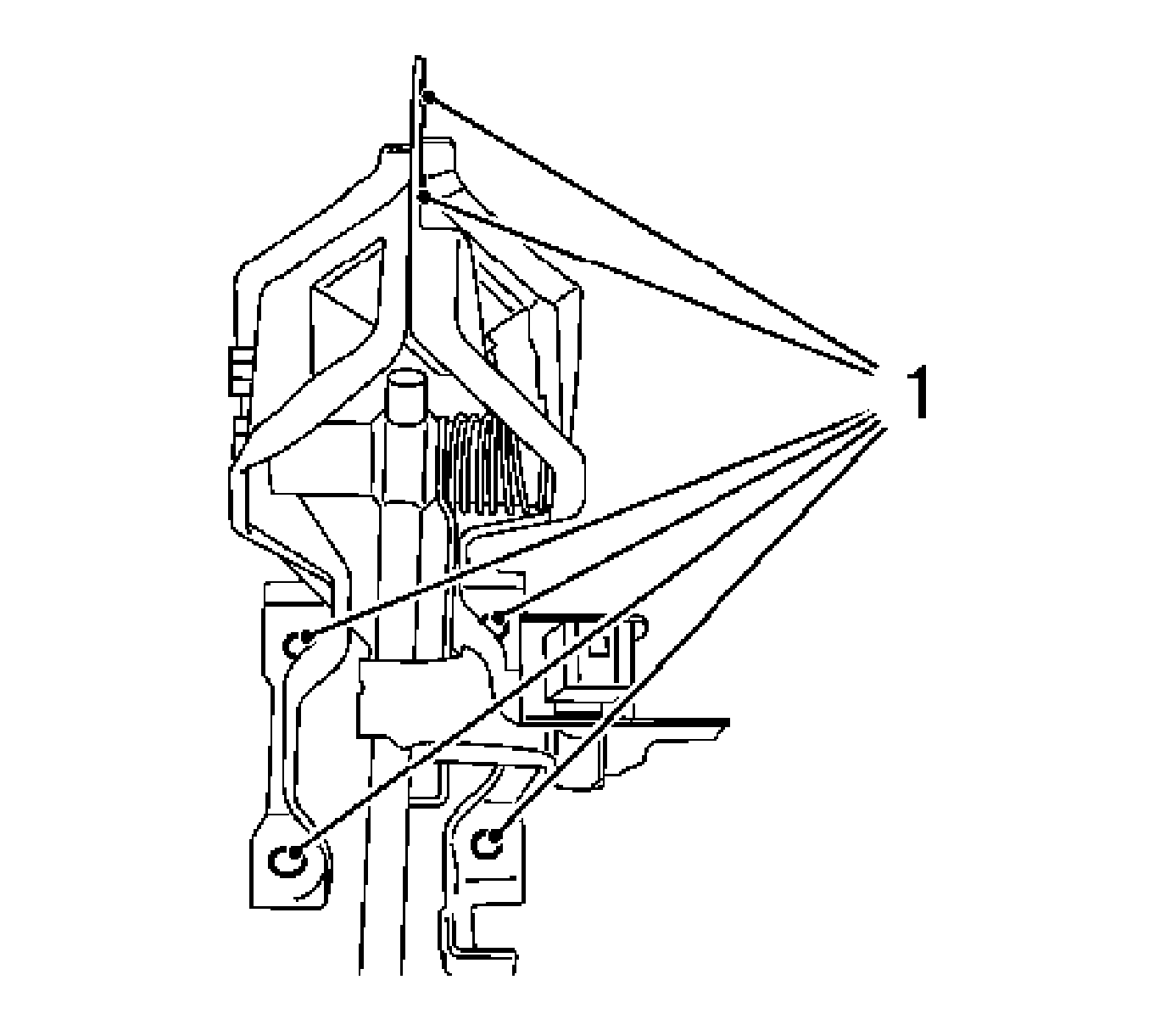
Remove the 3 bolts.

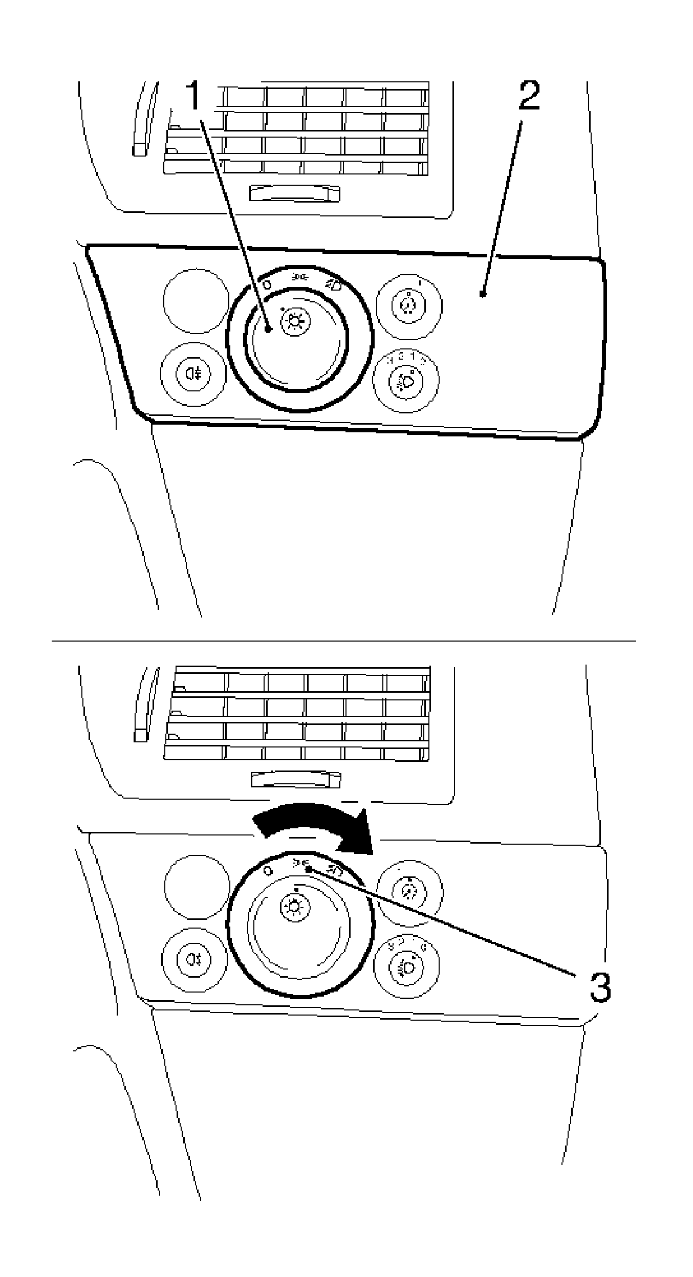
Note: To release the light switch center, press in the rotary switch (1) to position "0", bring pressed-in rotary switch to the central position (3), light switch center (2) has been released.
- Release the light switch center.
- Pull out the light switch center.

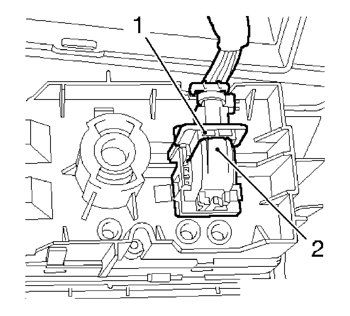
- Disconnect the wiring harness plug for the light switch center.
Disconnect the wiring harness plug.
| • | Press down the secondary fuse (2). |
- Remove the paneling of the lower instrument panel padding.
| • | Remove the paneling of the lower instrument panel padding downwards. |
- Remove the driver side footwell paneling.
Remove the 2 clips.
- Remove the air duct, driver side footwell.
Remove the expanding rivet.

- Lock the steering wheel in a straight ahead position.
| • | Turn the steering wheel to a straight ahead position. |
| • | Remove the ignition key. |
| • | Engage the steering wheel lock. |
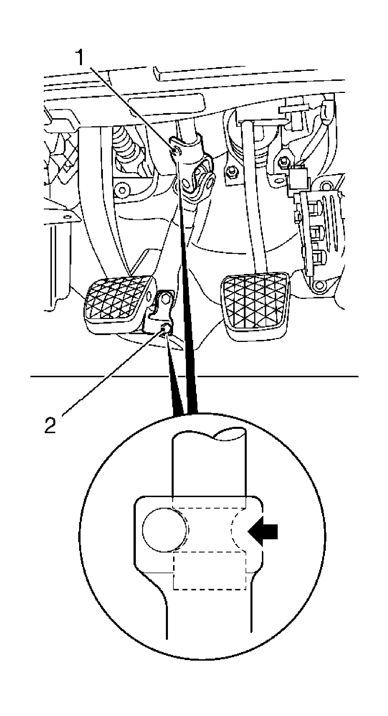
Note: Note installation position of the clamping bolts.
- Remove the 2 clamping bolts (1, 2).
- Press the intermediate spindle together slightly and remove.
- Remove the wiring harness.
| • | Disconnect the wiring harness plug for the brake light switch. |
| • | Disconnect the wiring harness plug, pedal sensor. |
- Remove the piston rod for the brake servo from the brake pedal.
| • | Remove the pedal bolt from the brake pedals (2). |
| • | Remove the retaining spring. |
- Remove the damping block.
- Remove the brake pedal with the bearing block.
- Remove the brake light switch (3) from the mounting.

- Install the brake light switch in the mounting.
Caution: Refer to Fastener Caution in the Preface section.
- Install the brake pedal with bearing block (1).
Tighten
Tighten the 4 nuts and 2 bolts to 20 N·m (15 lb ft).
- Insert the damping block.
- Install the piston rod for the brake servo to the brake pedal.
- Install the pedal bolt for the brake pedal.
| • | Install the retaining spring. |
- Install the wiring harness.
| • | Connect the wiring harness plug to the pedal sensor. |
| • | Connect the wiring harness plug, brake light switch. |

Note:
| • | Before inserting the clamping bolt, ensure that the groove (arrow) of the steering spindle aligns with the bore in the intermediate spindle. Clean the thread and insert the bolt with the locking compound. |
| • | Installation position of the clamping bolt. |
- Install the intermediate spindle to steering spindle.
| • | Push the intermediate spindle on to the steering spindle. |
Tighten
Tighten the steering spindle bolt to 24 N·m (18 lb ft).
Note:
| • | Ensure that the wheels are in the straight ahead position. |
| • | Before inserting the clamping bolt, ensure that the groove (arrow) of the steering gear spindle aligns with the bore in the intermediate spindle. Clean thread and insert bolts with locking compound. |
- Install the intermediate spindle to the steering gear.
Tighten
Tighten the intermediate spindle bolts (2) to 24 N·m (18 lb ft).
- Inspect the straight ahead position, adjust if necessary. Refer to
Straight Ahead Inspection.
- Install the air guide, driver side footwell.
Install the expanding rivet.
- Install the driver side footwell paneling.
Lock the 2 retaining clips.
- Install the lower instrument panel padding.
Install in the mounting.
Tighten
Tighten the 4 lower instrument panel padding bolts to 2.5 N·m (22 lb in).
- Install the light switch center.
| • | Connect the wiring harness plug. |
| • | Insert the light switch center. |
| • | Lock the switch to the left. |
- Install the casing for the steering column support tube at the bottom.
Tighten
Tighten the 3 casing for the steering column support tube bottom bolts to 0.7 N·m (6.2 lb in).
- Install the ignition switch panel.
- Install the casing for the steering column support tube at the top.
| • | Install the 2 clips steering column support tube paneling in the combined instrument panel. |
Tighten
Tighten the 3 casing for the steering column support tube top bolts to 0.7 N·m (6.2 lb in).


