Removal Procedure
- Remove the battery tray. Refer to
Battery Tray Replacement.
- Place the surge tank for coolant to one side.
Remove the surge tank from the support.

- Remove the automatic brake system (ABS) module.
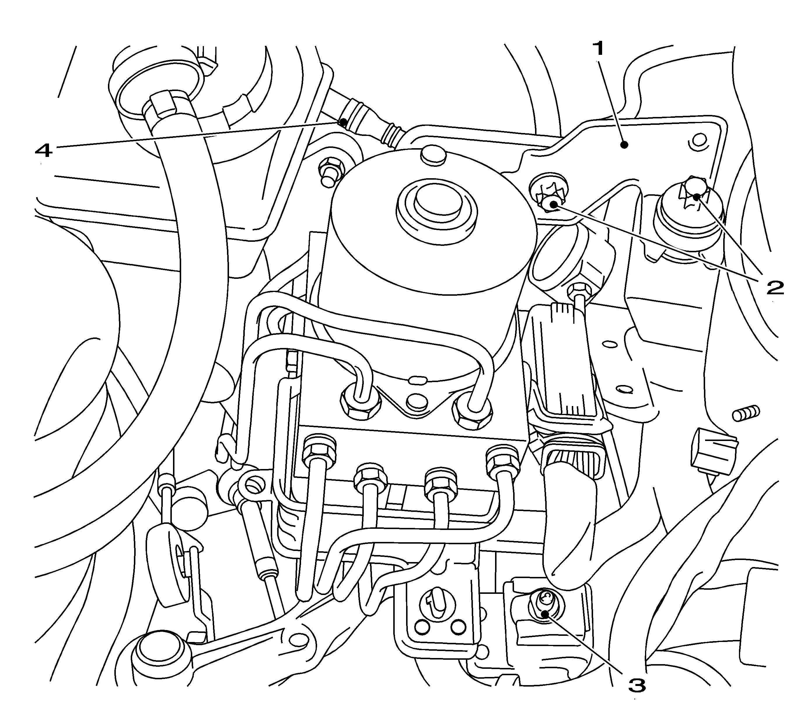
| • | Remove the ABS module at the top (1). |
| - | Remove the 2 bolts (2). |
| - | Disconnect the lead from the bracket. |
| • | Remove the ABS module at the bottom. |
- Remove the feed line (4) for the clutch master cylinder from the brake fluid reservoir.
Collect brake fluid and seal the opening.

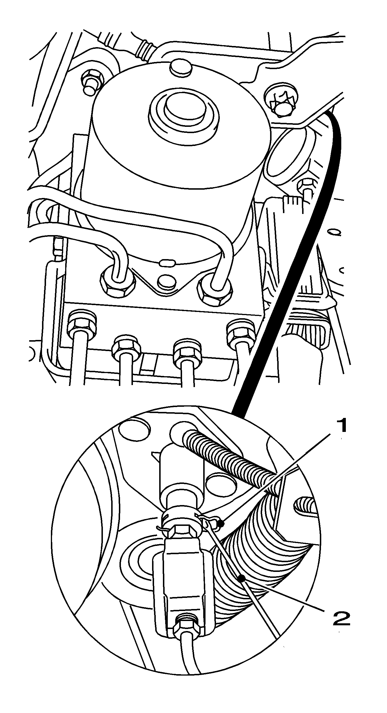
- Remove the retaining clamp (1) on the clutch master cylinder.
| • | Carefully push the ABS module to one side. |
| • | Release the retaining clamp using a screwdriver (2). |
- Release the pressure line for the clutch actuator with damper from the clutch master cylinder.

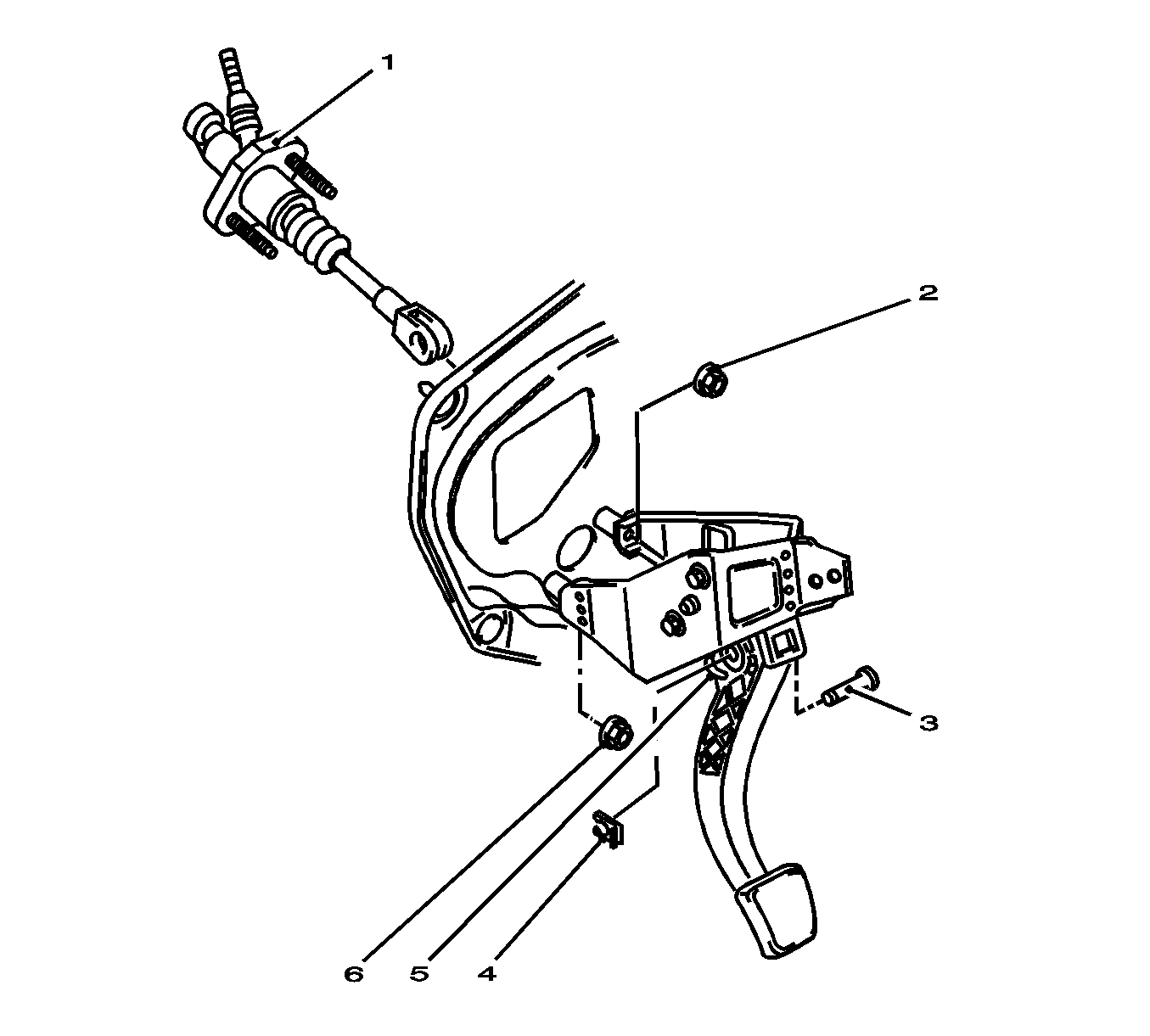
- Remove the clutch master cylinder.
| • | Remove the footwell trim on the driver side. |
| • | Disconnect the return spring (5). |
| • | Remove pin in the pedal (3). |
| - | Open the lock tab (4) with a screwdriver. |
| - | Remove the retaining plate from the pedal pin. |
| • | Remove the nuts (2) and (6) from the pedal support. |
Installation Procedure
Caution: Refer to Fastener Caution in the Preface section.
Note: Use new nuts.
- Install the clutch master cylinder.
| • | Install the clutch master cylinder in bulkhead. |
| • | Install the clutch master cylinder to the pedal support. |
Tighten
Tighten the nuts (2) and (6) to 20 N·m (15 lb ft).
| • | Install the pedal pin (3) |
| - | Connect the lock tab to the pedal pin. |
| - | Bend the retaining plate (4) together. |
| • | Install the return spring (5). |
| • | Install the driver side footwell trim. |

- Install the pressure line in the clutch slave cylinder.
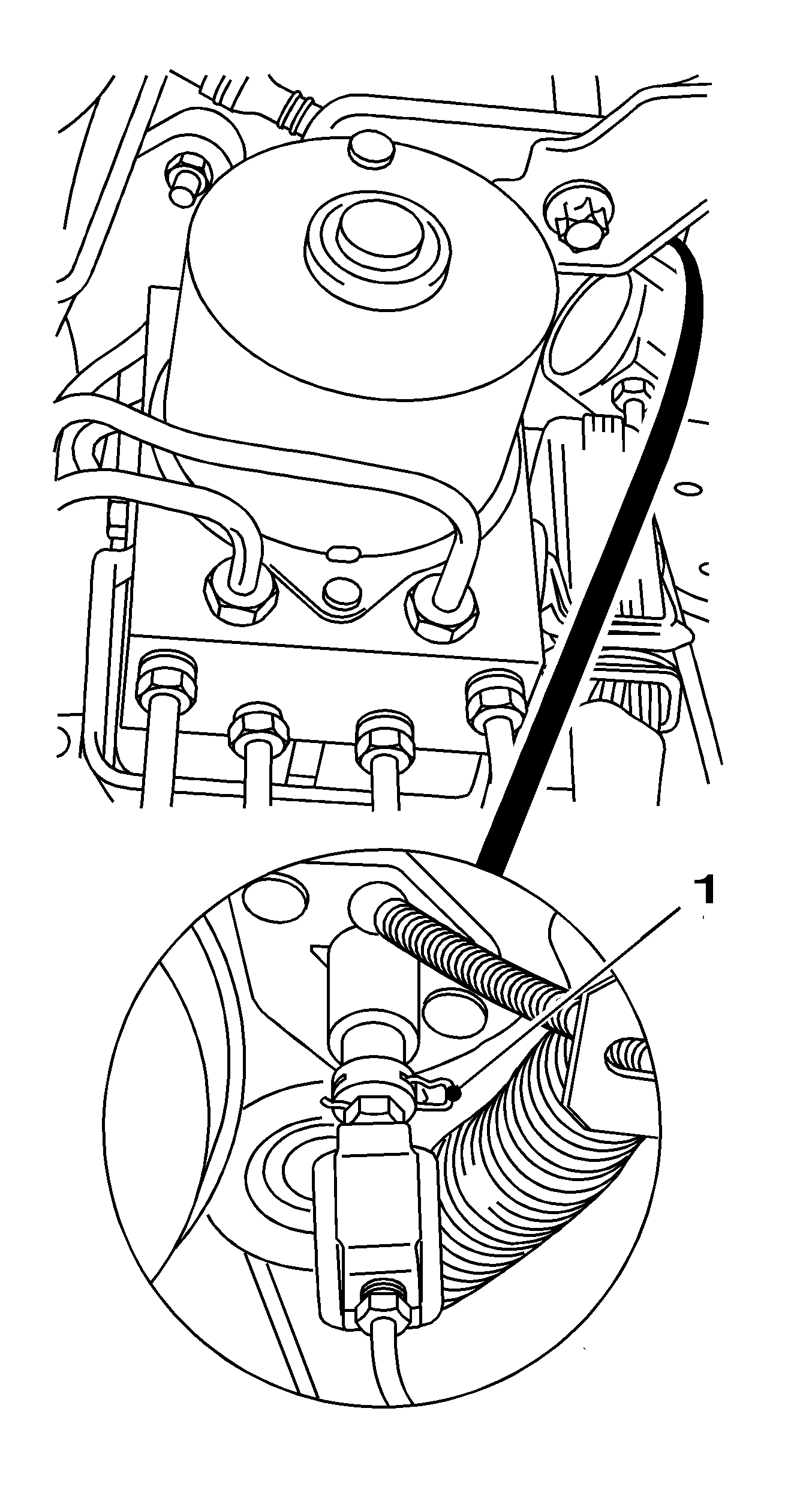
| • | Bend the retaining clamp (1) together slightly. |
| • | Carefully push the ABS module to one side. |
| • | Install the retaining clamp to the clutch master cylinder. |
| | Note: The pressure line must audibly engage.
|
| • | Push the pressure line into the clutch master cylinder. |

- Connect the feed line (4) for the clutch master cylinder to brake fluid reservoir.
- Install the ABS module.
| • | Attach the ABS module at the base. |
Tighten
Tighten the bolt (3) to 20 N·m (15 lb ft).
| • | Attach the ABS module bracket at the top (1). |
Tighten
Tighten the 2 bolts (2) to 20 N·m (15 lb ft).
| • | Connect the lead into the bracket. |
- Install the compensation tank for coolant.
Connect the compensation tank to the bracket.
- Install the battery tray. Refer to
Battery Tray Replacement.
- For reprogramming procedures, refer to
Control Module References.
- Bleed the hydraulic clutch. Refer to
Hydraulic Clutch Bleeding.


