For 1990-2009 cars only
Power Steering Pump Hoses and Pipes Replacement ZF
Removal Procedure
- Remove the front frame. Refer to Front Frame Replacement.
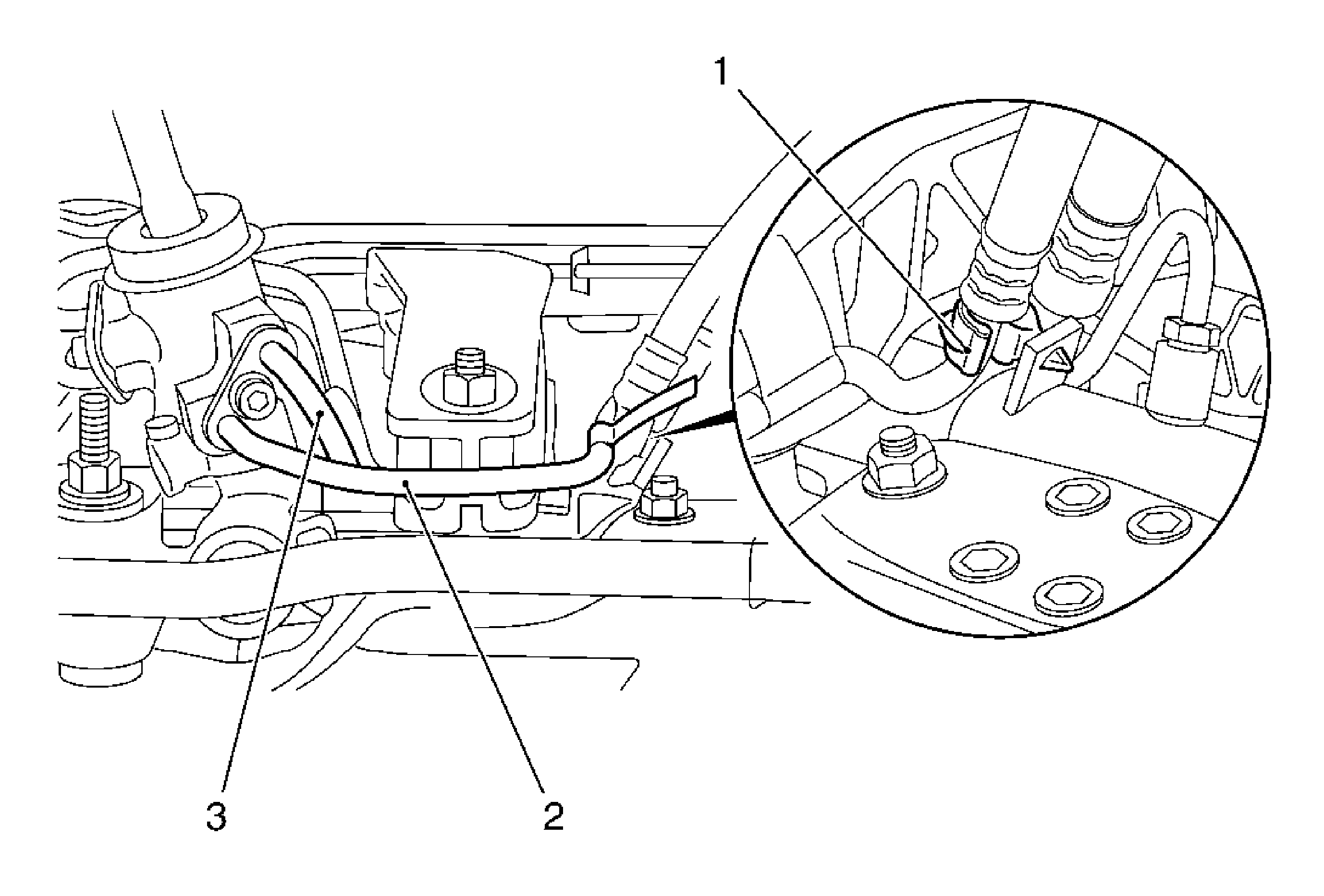
- Remove the holder (1).
- Remove the supply line (2) and the return line (3) from the steering gear.
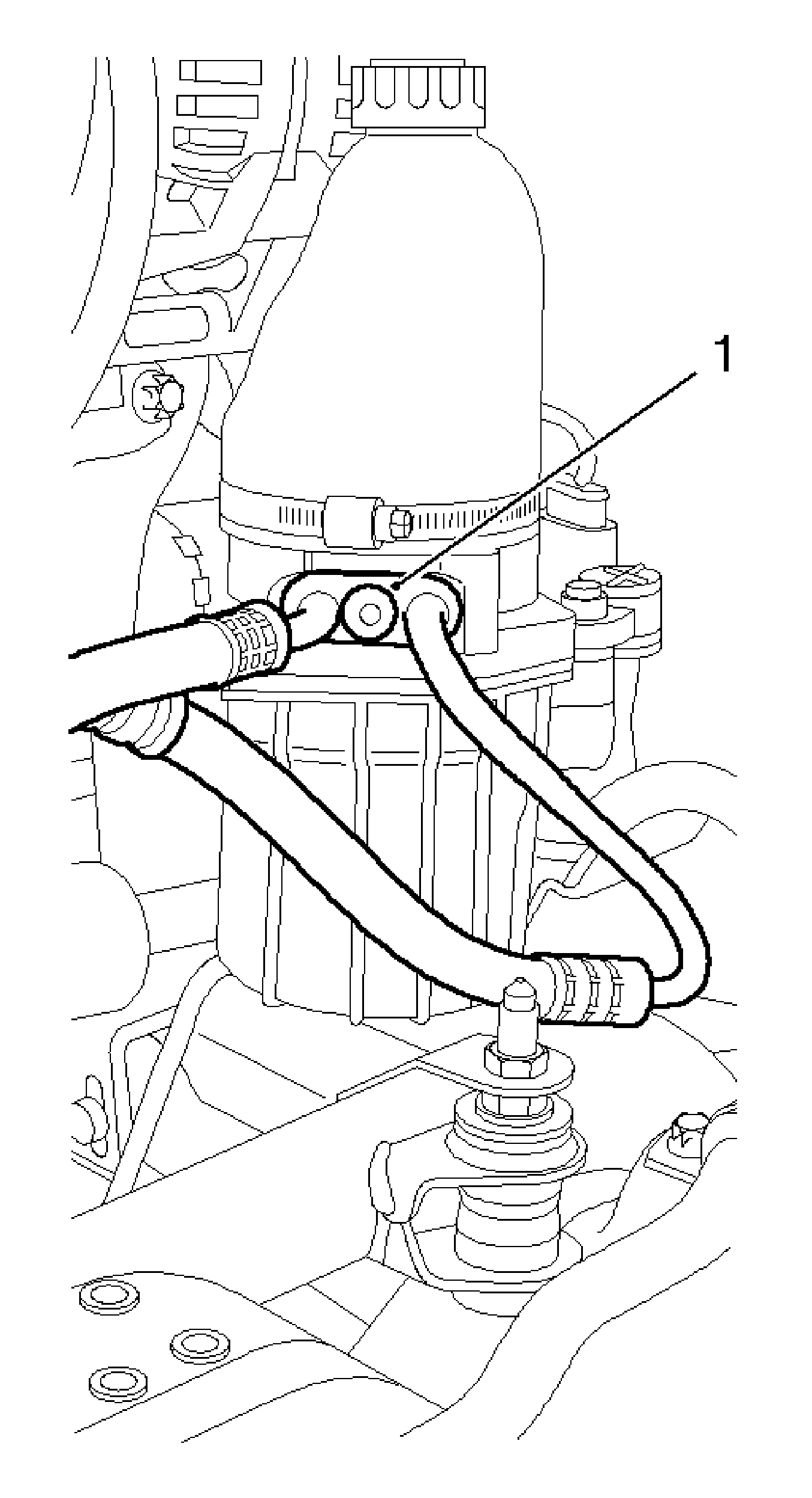
- Remove the supply and return lines from the electro-hydraulic supply unit.

Note: Oil will run out, use a drain pan.
Remove the bolt.

Note: Oil will run out, use a drain pan.
Remove the bolt (1).
Installation Procedure
- Install the supply and return lines to the steering gear with new seal rings.
- Install the supply and return lines to the electro-hydraulic supply unit with the new seal rings.
- Clip the holder for the supply and return lines to the steering gear.
- Install the front frame. Refer to Front Frame Replacement.
- Bleed the power steering system. Refer to Power Steering System Bleeding.
Caution: Refer to Fastener Caution in the Preface section.
Tighten
Tighten the bolt to 16 N·m (12 lb ft).
Tighten
Tighten the bolt to 16 N·m (12 lb ft).
Power Steering Pump Hoses and Pipes Replacement TRW without NR1, NS1, NS2
Special Tools
J 22610 Keystone Clamp Pliers
Removal Procedure
- Remove the front frame. Refer to Front Frame Replacement.
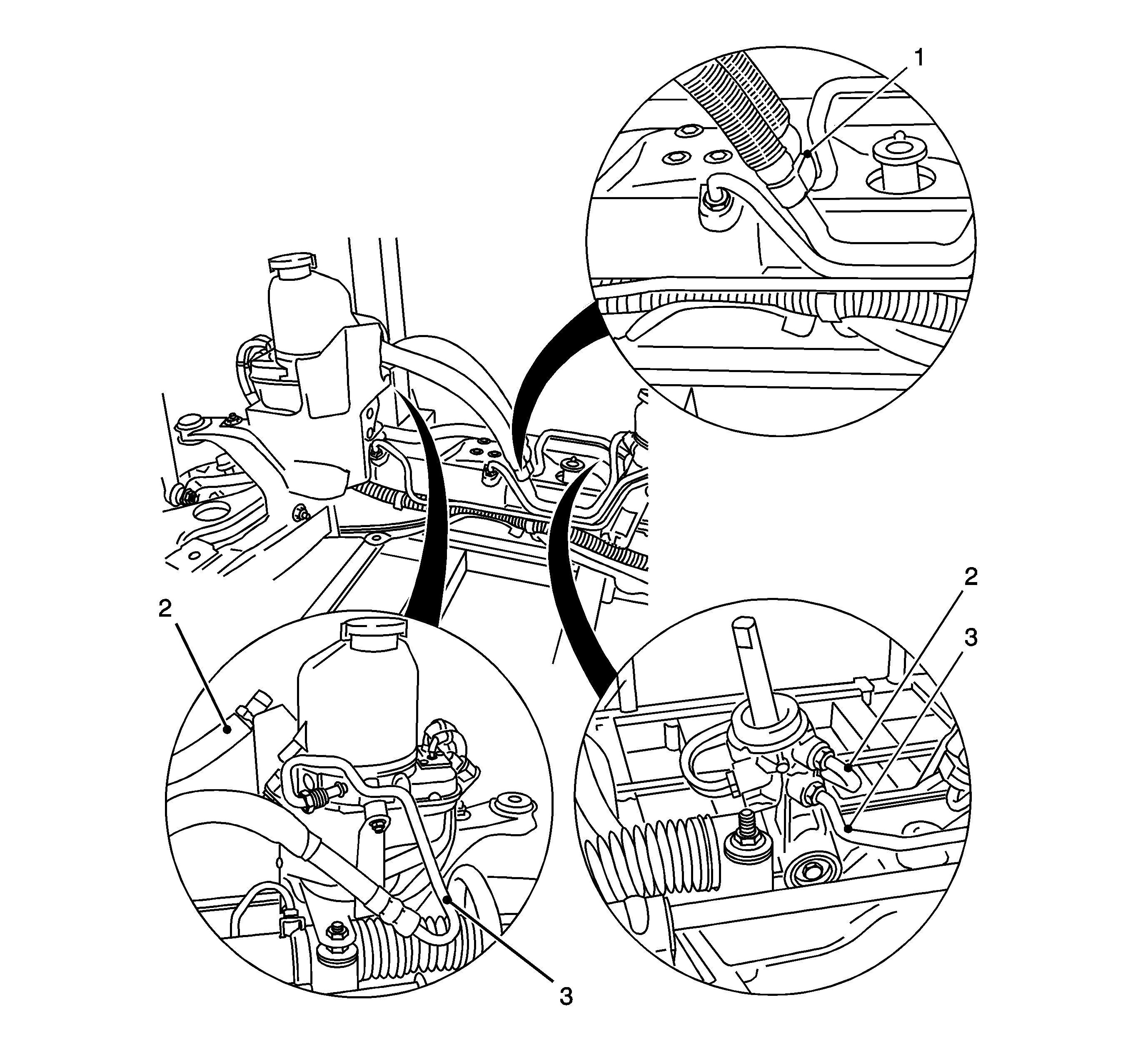
- Unclip the holder (1) for the supply and return lines from the steering gear.
- Place a drain pan under the power steering line connections and remove the supply line (3) and return line (4) from the steering gear.
- Detach the return line from the steering gear.
- Remove the supply line (3) from the electro-hydraulic supply unit.
- Remove the supply line from the steering gear.

Note: Oil runs out, use catchment tray.
Installation Procedure
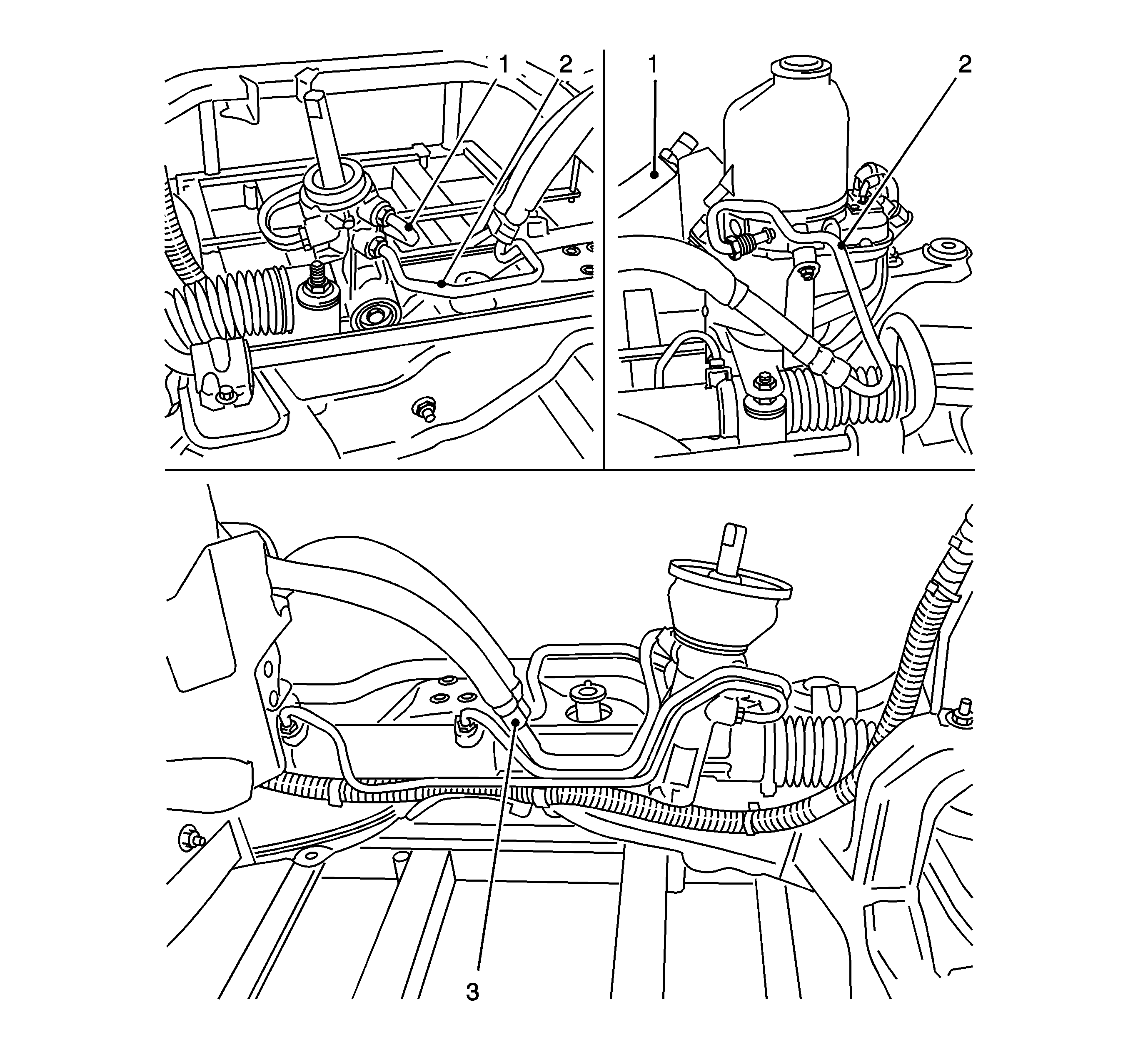
- Place the supply line (2) with the new seal ring on the steering gear.
- Place the supply line with the new seal ring on the electro-hydraulic supply unit.
- Place the return line (1) with the new seal ring on the steering gear.
- Place the return line (1) with new retaining strap to electro-hydraulic supply unit.
- Clip the holder (3) for the supply and return lines to the steering gear.
- Tighten the supply and return lines on the steering gear.
- Tighten the supply line on the electro-hydraulic supply line.
- Fasten the return line with the retaining strap and J 22610 to the electro-hydraulic supply unit.
- Install the front frame. Refer to Front Frame Replacement.
- Charge and bleed the hydraulic system. Refer to Hydraulic Brake System Bleeding.

Caution: Refer to Fastener Caution in the Preface section.
Tighten
Tighten to 30 N·m (22 lb ft).
Tighten
Tighten to 30 N·m (22 lb ft).
