Front Frame Replacement Removal
Special Tools
Removal Procedure
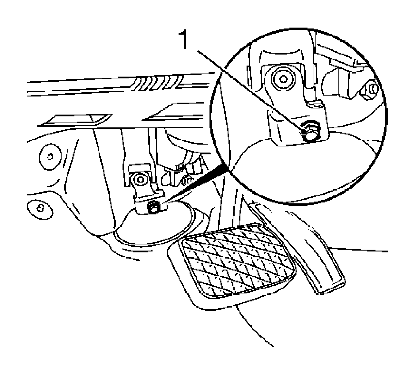
- Lock the steering wheel.
| 1.1. | Turn the steering wheel and front wheels to the straight-ahead position. |
| 1.2. | Remove the ignition key. |
| 1.3. | Engage the steering wheel lock. |
Note: The screw is accessible from the vehicle interior.
- Remove the intermediate spindle from steering gear.
| 2.1. | Remove the intermediate spindle clamping screw (1). |
| 2.2. | Pull the intermediate spindle from steering gear spindle. |
Warning: Refer to Battery Disconnect Warning in the Preface section.
- Disconnect the battery.
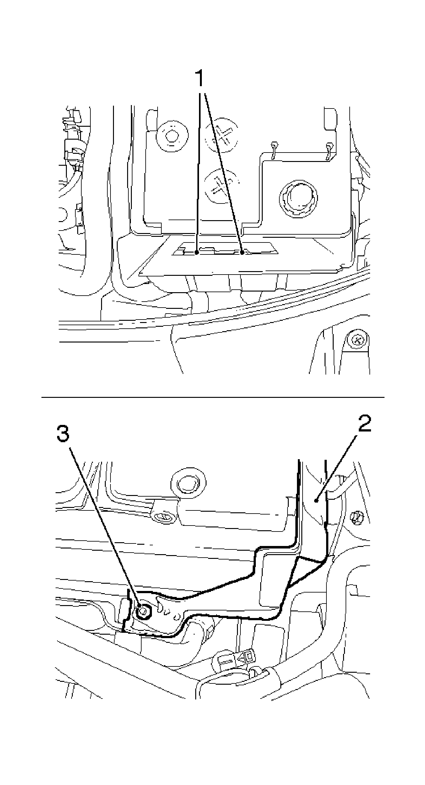
- Remove the battery shield (2).
| 4.1. | Remove the bolt (3). |
| 4.2. | Remove the 2 shields (1) from battery carrier. |
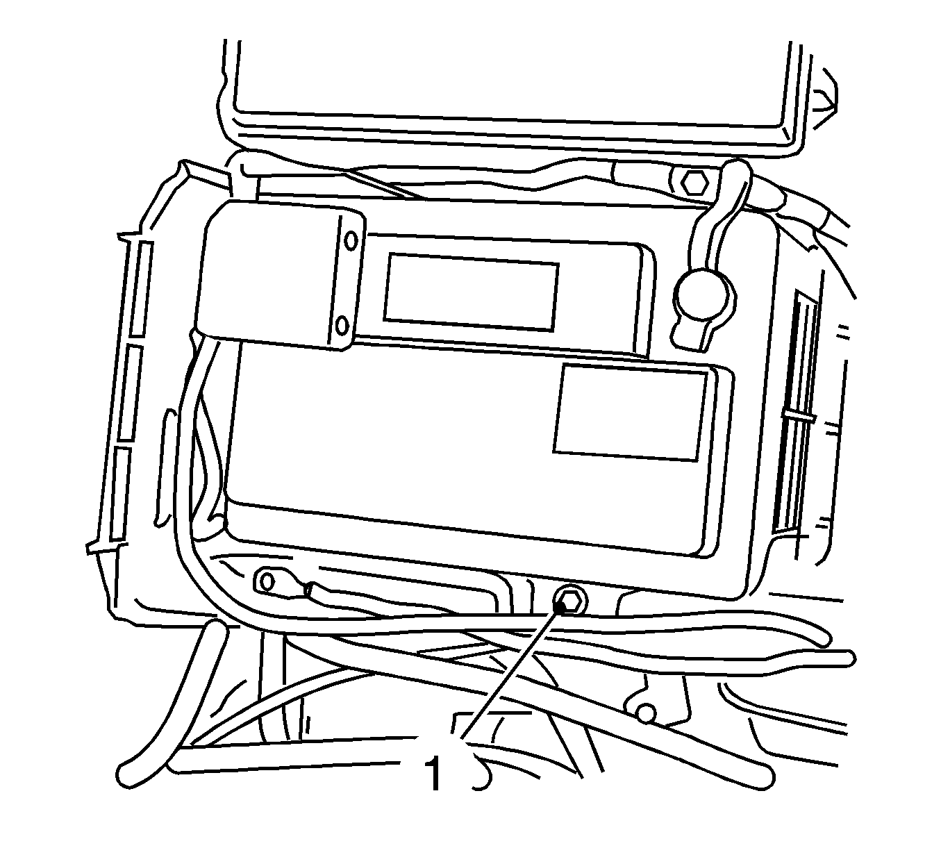
- Remove the battery holder (1).
Remove the bolt.
- Remove the battery.
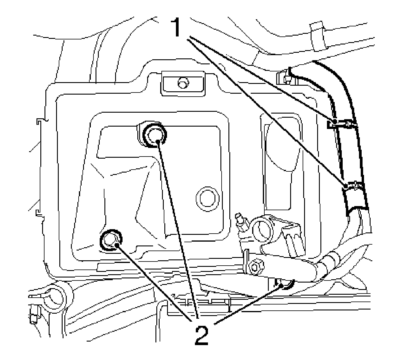
- Remove the battery carrier.
| 7.1. | Cut the 2 cable ties (1). |
| 7.2. | Remove the 3 bolts (2). |
Note: The cooling system remains closed.
- Disconnect the coolant expansion tank.
| 8.1. | Disconnect the wiring harness plug. |
| 8.2. | Place coolant expansion tank to one side. |
- Disconnect the 2 oxygen sensor wiring harness plugs.
- Remove the headlamps. Refer to
Headlamp Replacement - Left Side and
Headlamp Replacement - Right Side or
Headlamp Replacement.
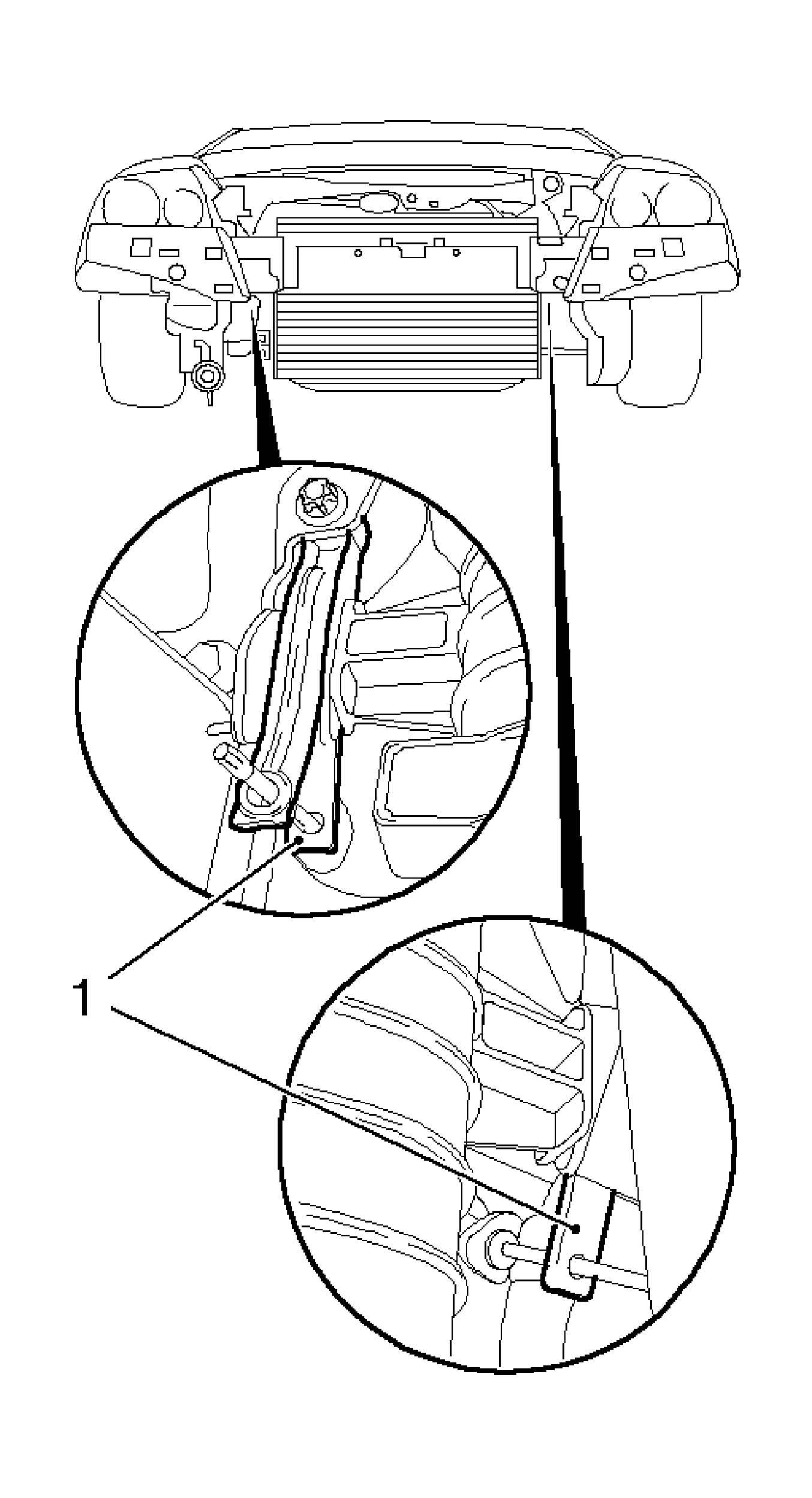
- Secure the radiator.
Insert a suitable wire bar into the bracket (1) at right and left.
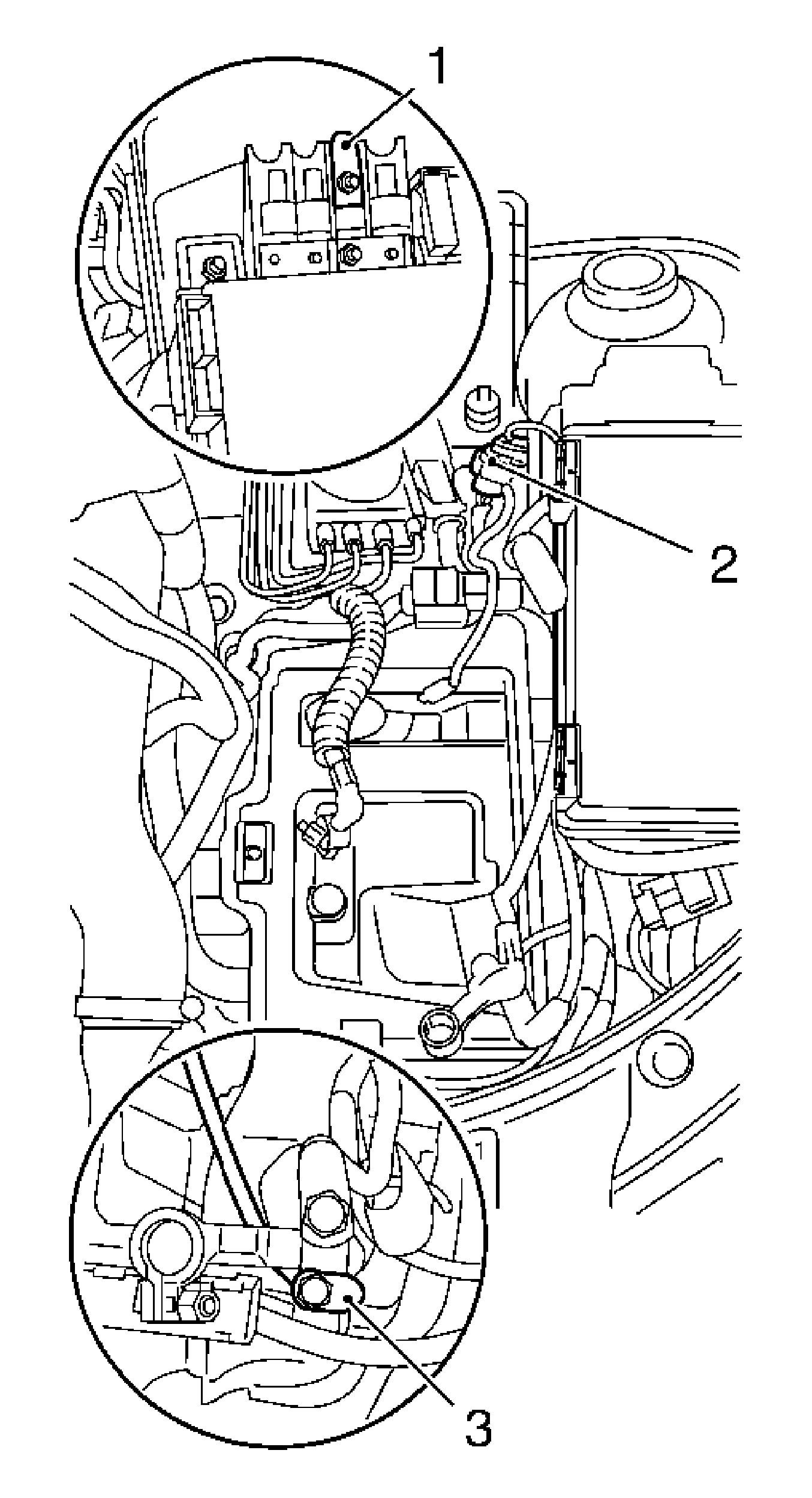
- Loosen the steering wiring harness.
| 12.1. | Detach the cover from positive distribution. |
| 12.2. | Disconnect the wiring harness from the fuse (1). |
| 12.3. | Disconnect the steering wiring harness (2). |
| 12.4. | Disconnect the steering wiring harness ground cable (3) from ground terminal. |
| | Note: Pay attention to cable routing.
|
| 12.5. | Expose the steering wiring harness, access required from below. |
| 12.6. | Remove the cable ties. |
| 12.7. | Remove the wiring harness from the bracket. |
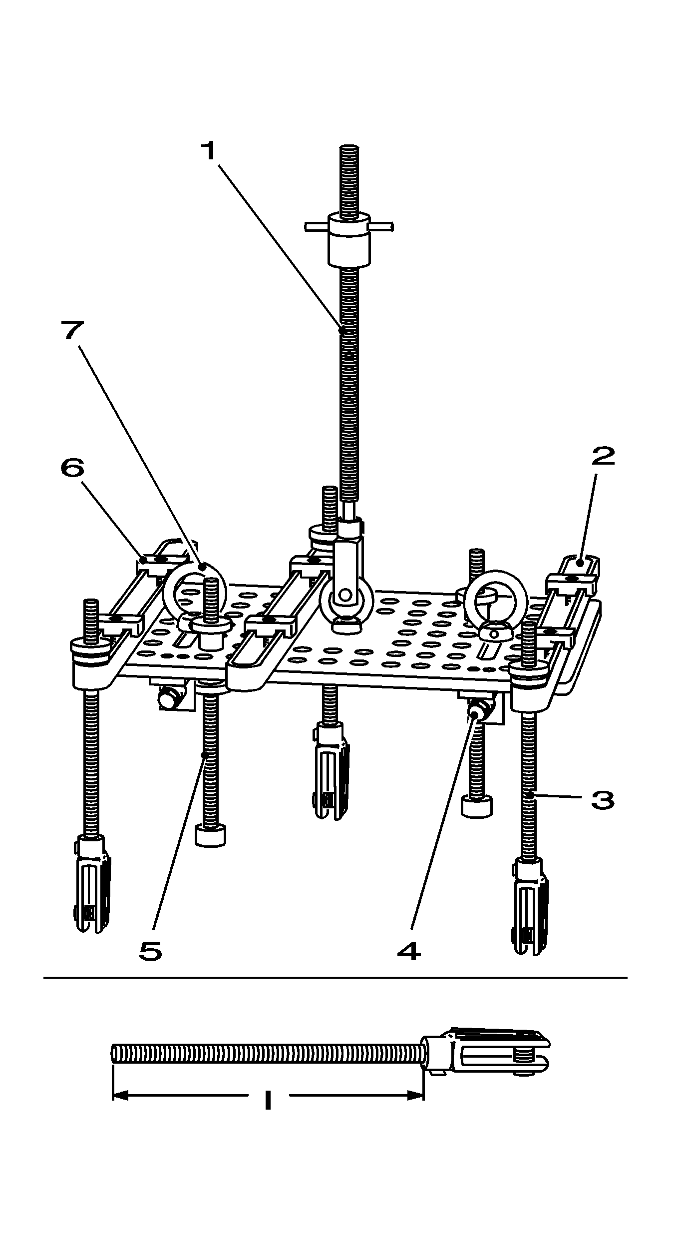
Note:
MKM-883-1 and
MKM-883-2 are used to ensure the engine will be in a horizontal position after removal of the front frame.
- Prepare for attachment of
MKM-883-1 and
MKM-883-2 .
MKM-883-2
| • | Retaining spindle (3 off) (3) |
| • | Support spindles (2 off) (5) |
| • | Tensioning nuts (6 off) (6) |
| • | First of all the alignment and attachment of
MKM-883-2 will be described below on an engine-specific basis. |
- Attach
MKM-883-2 , for U18 XER.
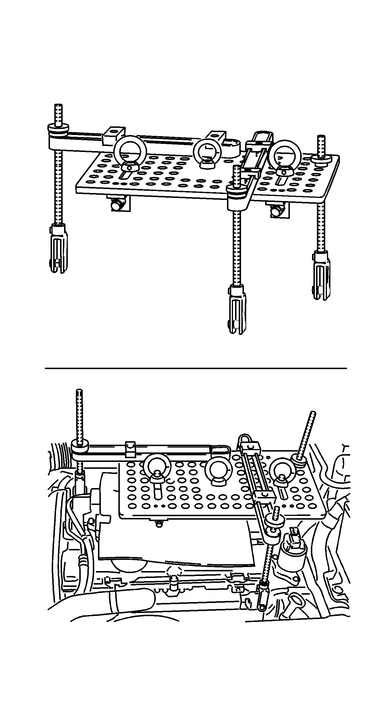
- Remove the upper engine cover.
| 15.1. | Remove the oil filler cap. |
| 15.2. | Install the oil filler cap. |
Note: Read the manufacturer's instructions before attaching
MKM-883-1 and
MKM-883-2 .
- Preassemble
MKM-883-2 with fastening spindles, arms and supporting spindle as shown. Ensure that the hexagon drives point forwards.
- Place
MKM-883-2 on engine and attach fastening spindles to engine transport shackles.
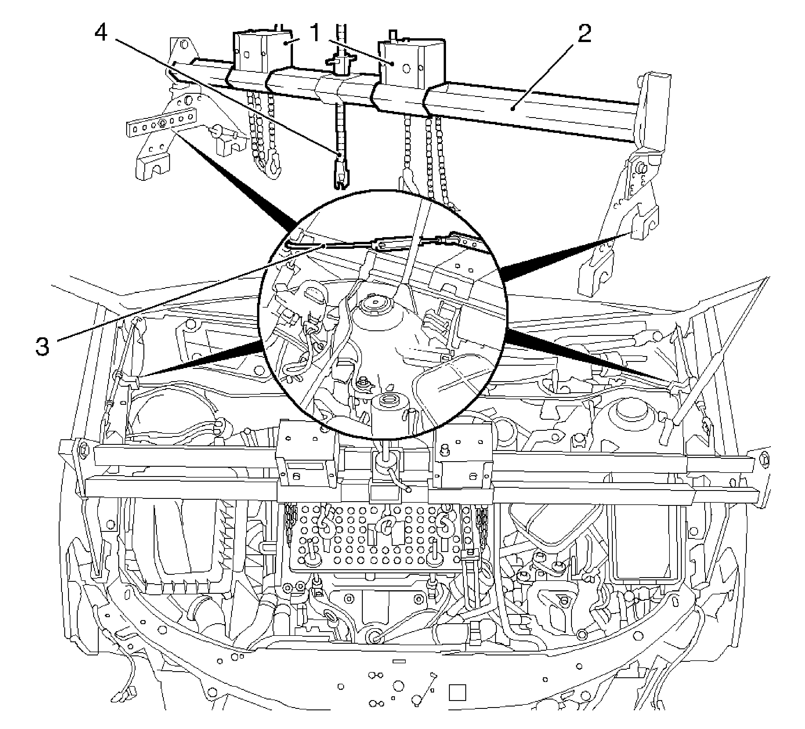
- Attach
MKM-883-1 .
MKM-883-1
Note: Prevent from tilting using safety hooks (3) at engine hood hinge and wing.
- Position
MKM-883-1 .
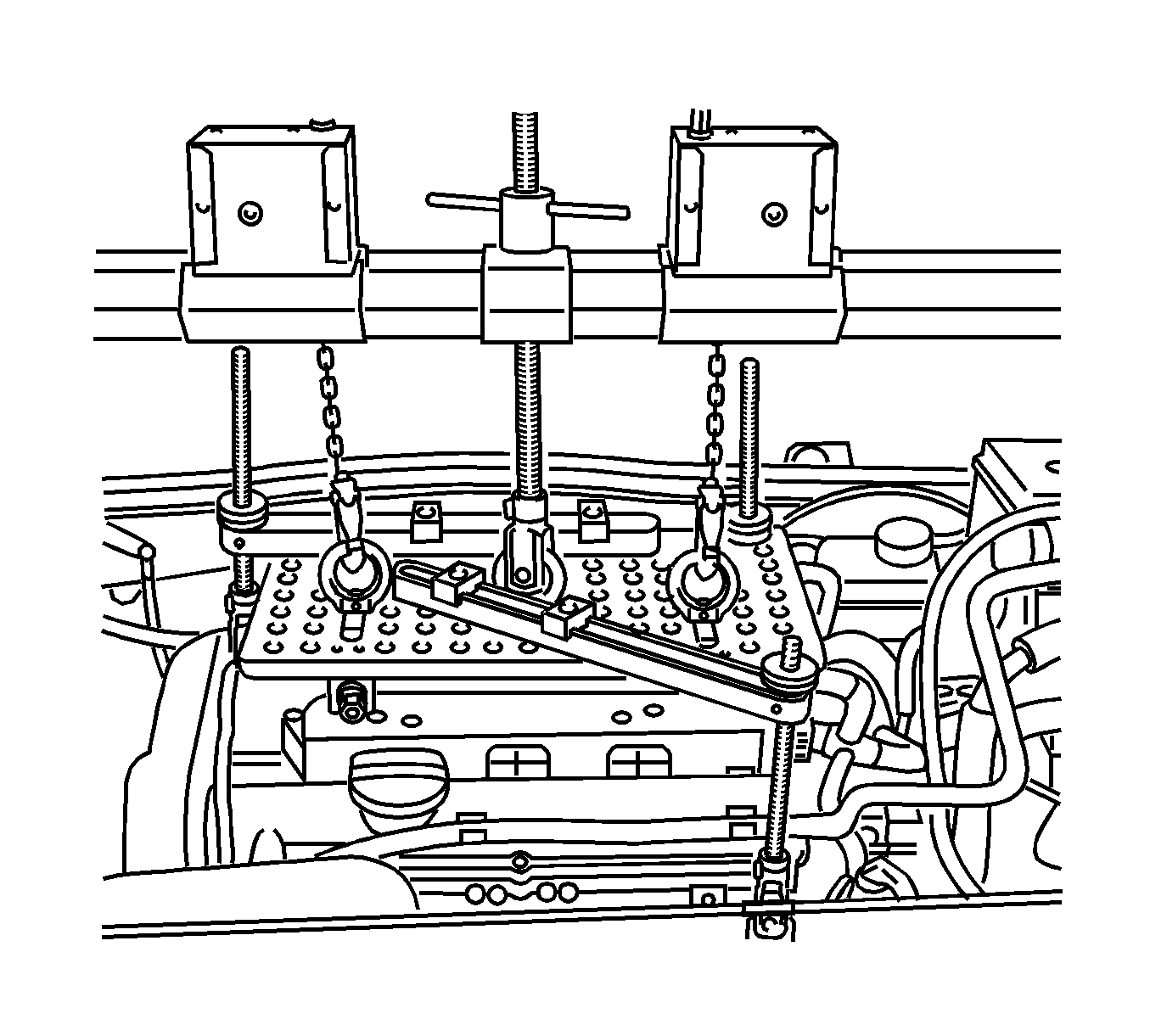
- Attach chain hook to the two outer eye nuts of
MKM-883-2 .
- Rotate the 2 tensioning chain drives until tensioning chains are under slight amount of pretension.
Note: MKM-883-2 must be in a horizontal position. Fastening spindles must be attached to the engine shackles so that they are vertical - if necessary, push arms and secure with clamping nuts
The tensioning chains must be in an exactly vertical position above the two outer ring nuts.
- Align
MKM-883-2 .
Evenly tension the fastening spindles by rotating the knurled nuts.
- Install the retaining spindles to the center ring nut.
- Apply slight tension to the retaining spindle.
- Remove the 2 front wheels.
- Remove the right engine splash guard.
| 26.1. | Remove the 4 bolts. |
| 26.2. | Remove the 2 body-bound rivets. |
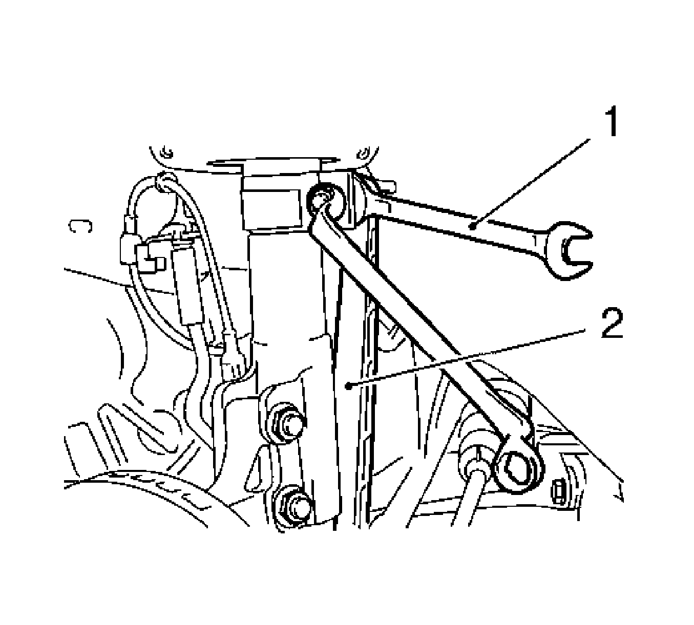
- Remove the right and left swing arms (2) from spring strut support tube.
Counterhold at flattened areas with open-ended wrench (1).
- Release the tie rod ends from the steering knuckle. Refer to
Steering Linkage Outer Tie Rod Replacement.
- Remove the guide joint from the steering knuckle.
| 29.1. | Remove the guide joint bolt at both sides. |
| 29.2. | Pull the guide joint out of steering knuckle. |
- If present, remove lower engine compartment cover.
- Remove the front exhaust pipe with catalytic converter and center muffler. Refer to
Mid Muffler Replacement.
- Detach the shift guide from shift rod transmission.
| 32.1. | Remove the shift rod clamp. |
| 32.2. | Detach the shift guide from shift rod. |
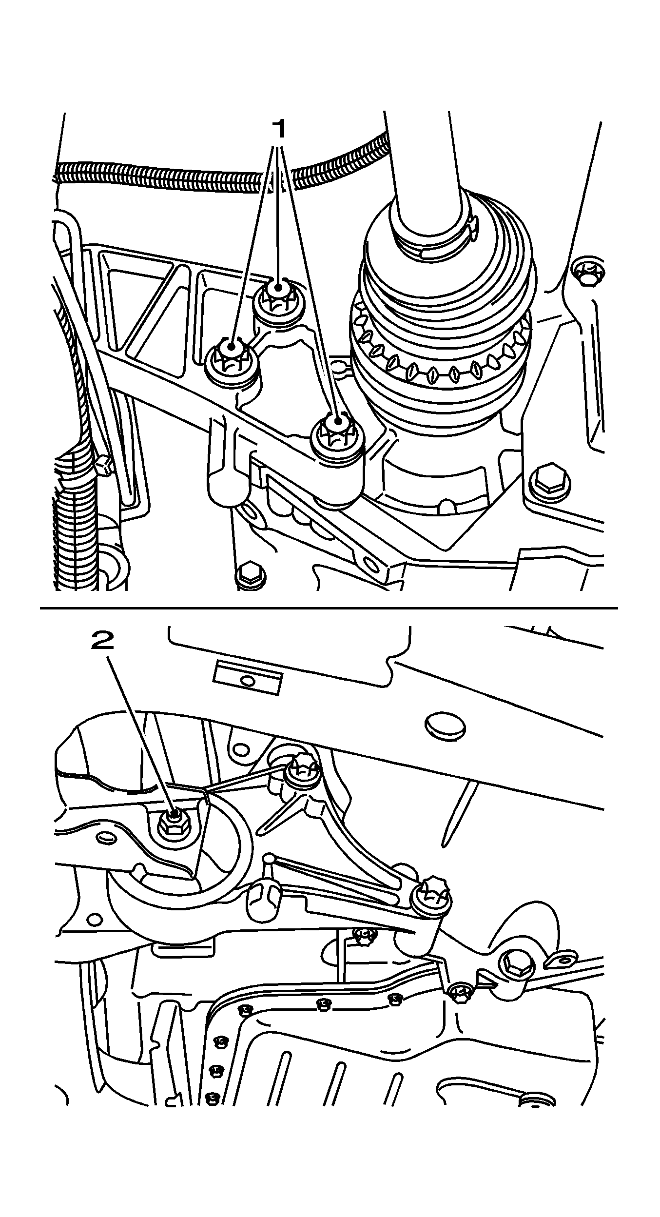
- Remove the engine damping block rear bracket (1) from the transmission.
Remove the 3 bolts.
- Detach the front engine damping block from the front frame.
| 34.2. | Remove the bolt (2). |
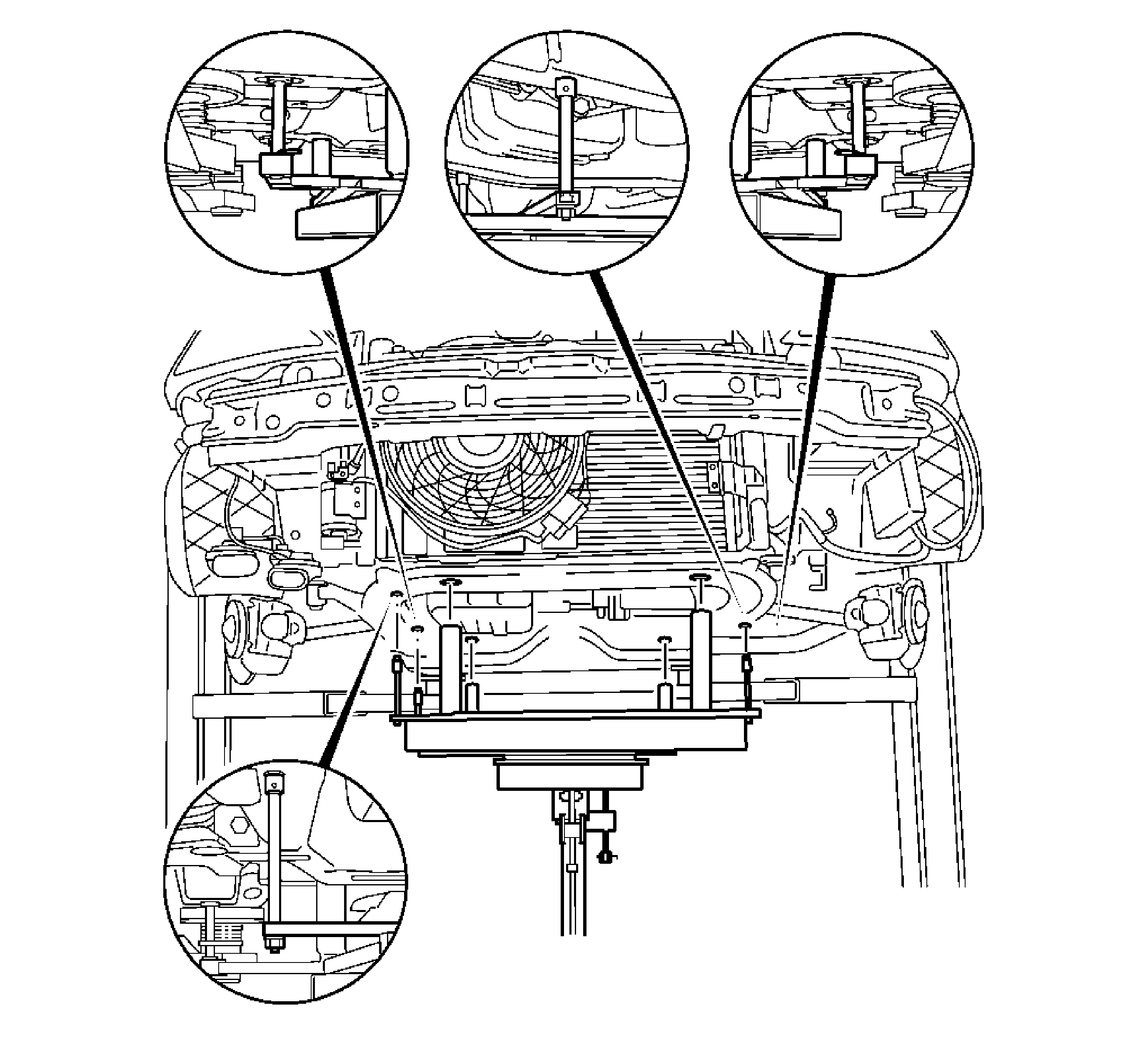
- Attach
KM-904 and
KM-6390 to hydraulic jack.
Note: Ensure that the guide pins of
KM-6390 are seated in the guide holes in the vehicle underbody. The front frame bolts must not be removed using an impulse or impact screwdriver. Pay attention
to different bolt lengths and different washers.
- Place the hydraulic jack beneath the frame body (no clearance).
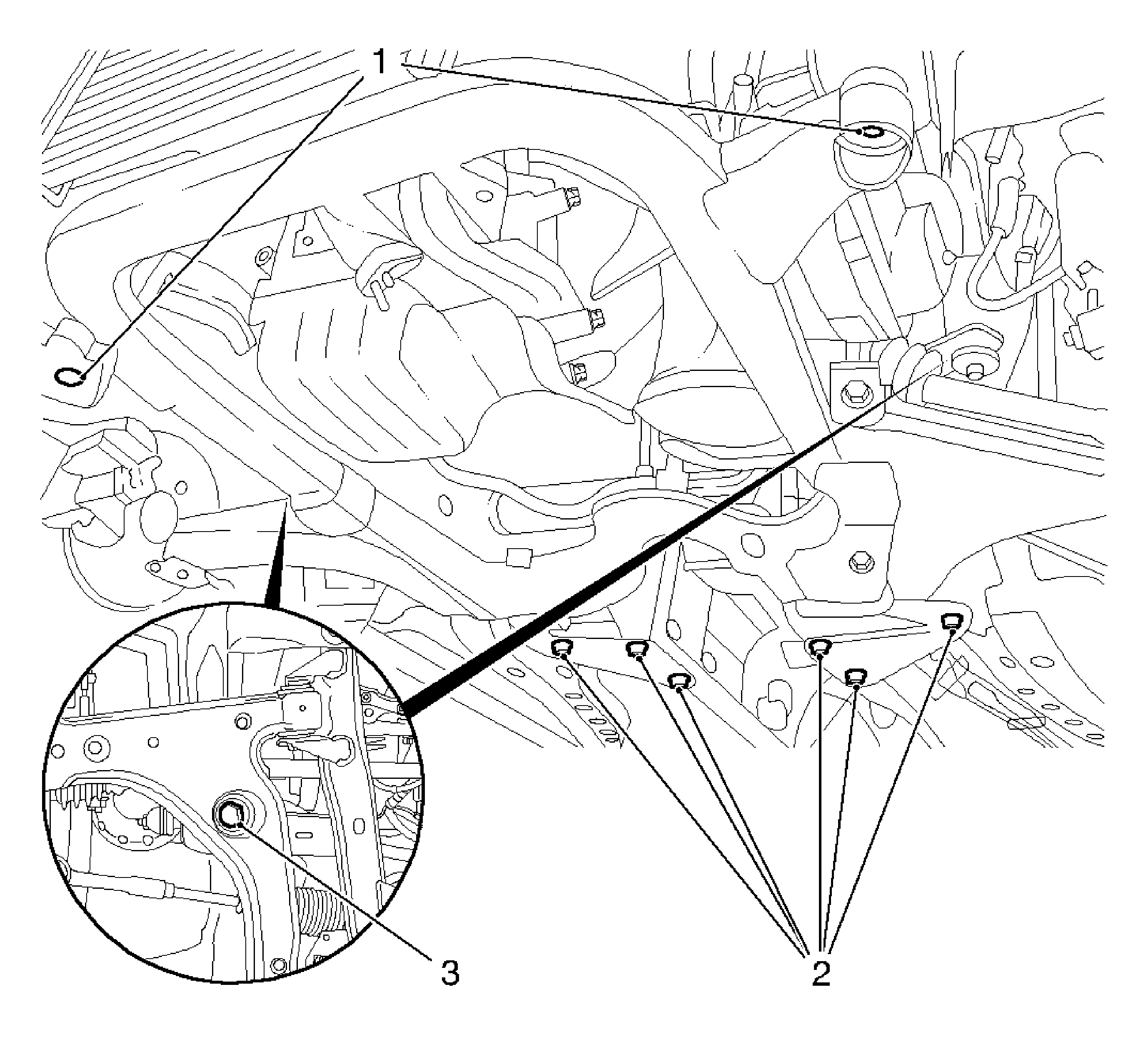
Note: For greater clarity, the illustration shows the front frame without hydraulic jack and centring mount.
- Detach the front frame from the front frame.
| 37.1. | Remove the 6 bolts (2). |
| 37.2. | Remove the triangular plates. |
| 37.3. | Remove the 2 bolts (1), right and left. |
| | Note: Ensure that no attaching parts are damaged. Pay attention to steering wiring harness.
|
| 37.4. | Remove the 2 bolts (3). |
- Carefully lower front frame using hydraulic jack.
- Replace the front frame. Refer to
Front Frame Replacement.
Installation Procedure
Note: Before installing the front frame, check the threads of captive nuts for free movement.
- Install the front frame to the front frame.
Note: Ensure that the guide joint protective sleeves are not damaged.
- Raise the front frame with hydraulic jack,
KM-904 and
KM-6390 .
Caution: Refer to Fastener Caution in the Preface section.
Note:
| • | Ensure that the guide pins of
KM-6390 are seated in the guide holes in the vehicle underbody. |
| • | Ensure that the engine damping blocks front and rear are positioned perfectly. |
| • | Be careful of the wiring harness for steering. Installing the front frame with an impulse screwdriver or impact screwdriver is not permitted. Note the bolt lengths and washers. Tighten bolts evenly at all fastening points. |
- Align the front frame and tighten the 4 new bolts to
90 N·m (67 lb ft) plus 45 degrees plus 15 degrees.
- Install the triangular plates and tighten the 6 new bolts to
90 N·m (67 lb ft) plus 45 degrees plus 15 degrees.
- Detach the hydraulic jack,
KM-904 and
KM-6390 .
Note: Clean the thread and insert bolts with locking compound.
- Install the bracket for rear engine damping block to the transmission and tighten to
80 N·m (59 lb ft).
- Install front engine damping block to the front frame and tighten to
55 N·m (40 lb ft).
| 7.2. | Install the new nut. |
- In vehicles with manual transmission, install the shift guide to shift rod.
| 8.1. | Slide onto the shift rod. |
| 8.2. | Install the clamping screw loosely. |
| 8.3. | Place rocker onto the shift guide bracket. |
| 8.4. | Secure using new retaining clip. |
- Install the front exhaust pipe, catalytic converter and center muffler. Refer to
Mid Muffler Replacement.
- If present, install the lower engine compartment cover.
- Connect the guide joint to the steering knuckle on the right and left side and tighten the 2 new nuts to
50 N·m (37 lb ft).
- Connect the tie rod end to the steering knuckle. Refer to
Steering Linkage Outer Tie Rod Replacement.
- Install the swing arm to the spring strut support tube on the right and left side and tighten to
55 N·m (40 lb ft).
| 13.2. | Counterhold at the two flattened areas with open-ended wrench. |
- Install the right lower wheelhouse paneling and tighten to
5 N·m (44 lb in).
- Install the front paneling. Refer to
Front Bumper Fascia Replacement.
- Install the right and left engine splash guards.
- Install the front wheels and tighten to
110 N·m (81 lb ft).
- Disconnect
MKM-883-1 and
MKM-883-2 from the engine.
- Connect the steering wiring harness.
- Connect the ground connection to insulated ground terminal.
- Connect the steering wiring harness plug.
- Install the coolant expansion tank to bracket.
- Install the upper engine cover.
| 23.1. | Remove the oil filler cap. |
| 23.2. | Install the upper engine cover. |
| 23.3. | Install the 2 bolts and tighten to
8 N·m (71 lb in). |
| 23.4. | Install the oil filler cap. |
- Install the headlamps. Refer to
Headlamp Replacement - Left Side and
Headlamp Replacement - Right Side or
Headlamp Replacement.
- Remove the wire brackets for securing radiator.
- Position the wheels in straight-ahead position.
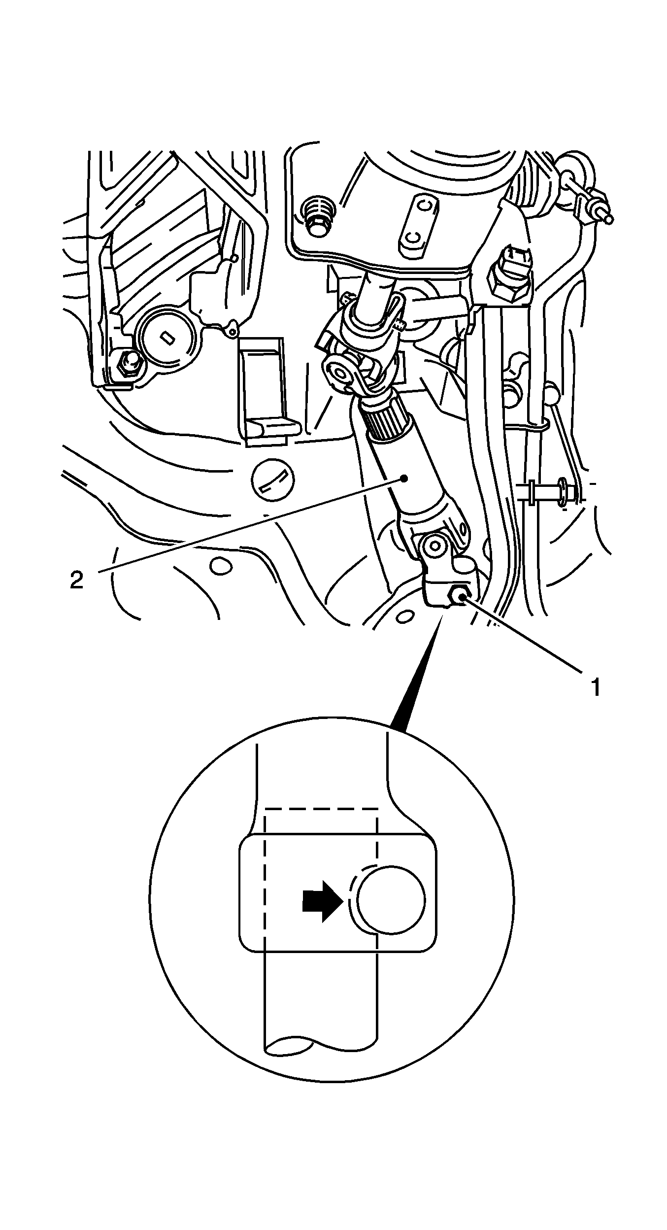
Note:
| • | Before inserting the clamp bolt (1) make certain that the steering shaft groove (arrow) is flush with the intermediate shaft bore. |
| • | Clean thread and screw in bolt with locking compound. |
- Slide the intermediate spindle (2) onto steering gear spindle and tighten clamping bolt (1) on intermediate shaft to
24 N·m (18 lb ft).
- For vehicles with shift guide, adjust the shift. Refer to
Selector Lever Link Adjustment.
- Install the battery carrier and tighten the 3 bolts to
15 N·m (11 lb ft).
- Connect the 2 cable ties.
- Install the battery.
- Install the battery shield.
- Install the bolt.
Connect the 2 shield, battery carrier.
- Install the battery holder and tighten the bolt to 7 N·m (62 lb in).
- Connect the battery.
Connect the positive cable.
Connect the ground cable.
- For programming procedures, refer to
Control Module References.
Front Frame Replacement Replacement
Removal Procedure
- Remove the front frame. Refer to
Front Frame Replacement.
- Detach the 2 radiator brackets (1) from the front frame.
- Detach the stabilizer (4) from the front frame. Refer to
Stabilizer Shaft Replacement.
- Detach the rear engine damping block bracket (2) from engine damping block.
- Detach the rear engine damping block (5) from front frame.
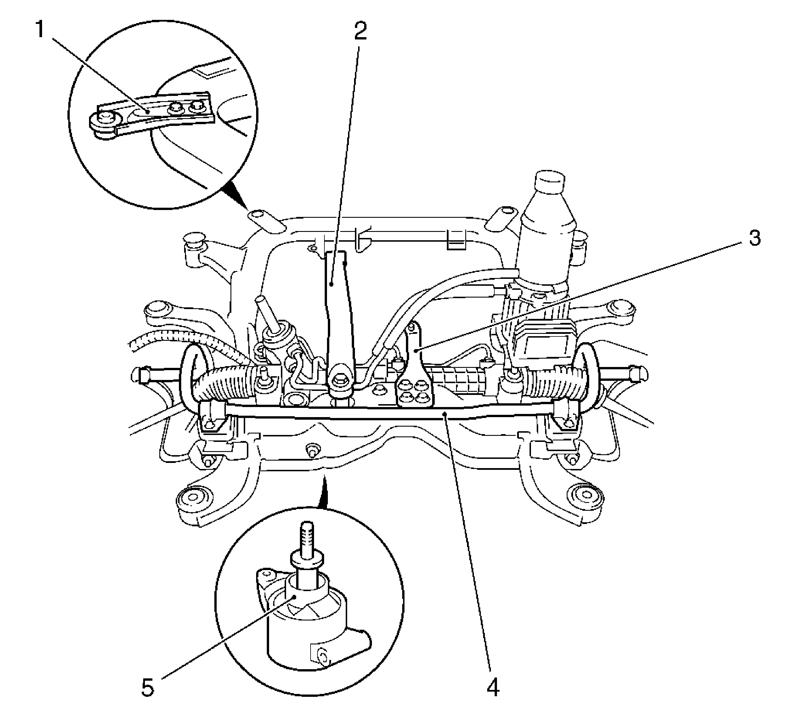
- For the vehicles with manual transmission, detach the shift guide bracket (3) from the front frame.
- Detach the electrohydraulic supply unit from the front frame. Refer to
Electronic Brake Control Module Replacement.
- Detach the steering gear from front frame. Refer to
Steering Gear Replacement.
- Detach the left and right control arms from the front frame. Refer to
Lower Control Arm Replacement.
Installation Procedure
- Install a new damping bushings in front frame. Refer to
Front Frame Cushion or Insulator Replacement.
Note: Only tighten bolted connection loosely. The bolted control arm connection to the front frame is tightened at vehicle trim height.
- Connect the left and right control arms to front frame.
| • | Install the 4 new nuts. |
Caution: Refer to Fastener Caution in the Preface section.
- Attach the rear engine damping block (4) to the front frame.
Install the 2 new nuts (2, 5).
Tighten
Tighten to 55 N·m (40 lb ft).
- Install the steering gear to the front frame. Refer to
Steering Gear Replacement.
- Install the electrohydraulic supply unit to the front frame. Refer to
Electronic Brake Control Module Replacement.
- For the vehicles with manual transmission, attach the shift guide bracket to the front frame.
Tighten
Tighten to 20 N·m (15 lb ft).
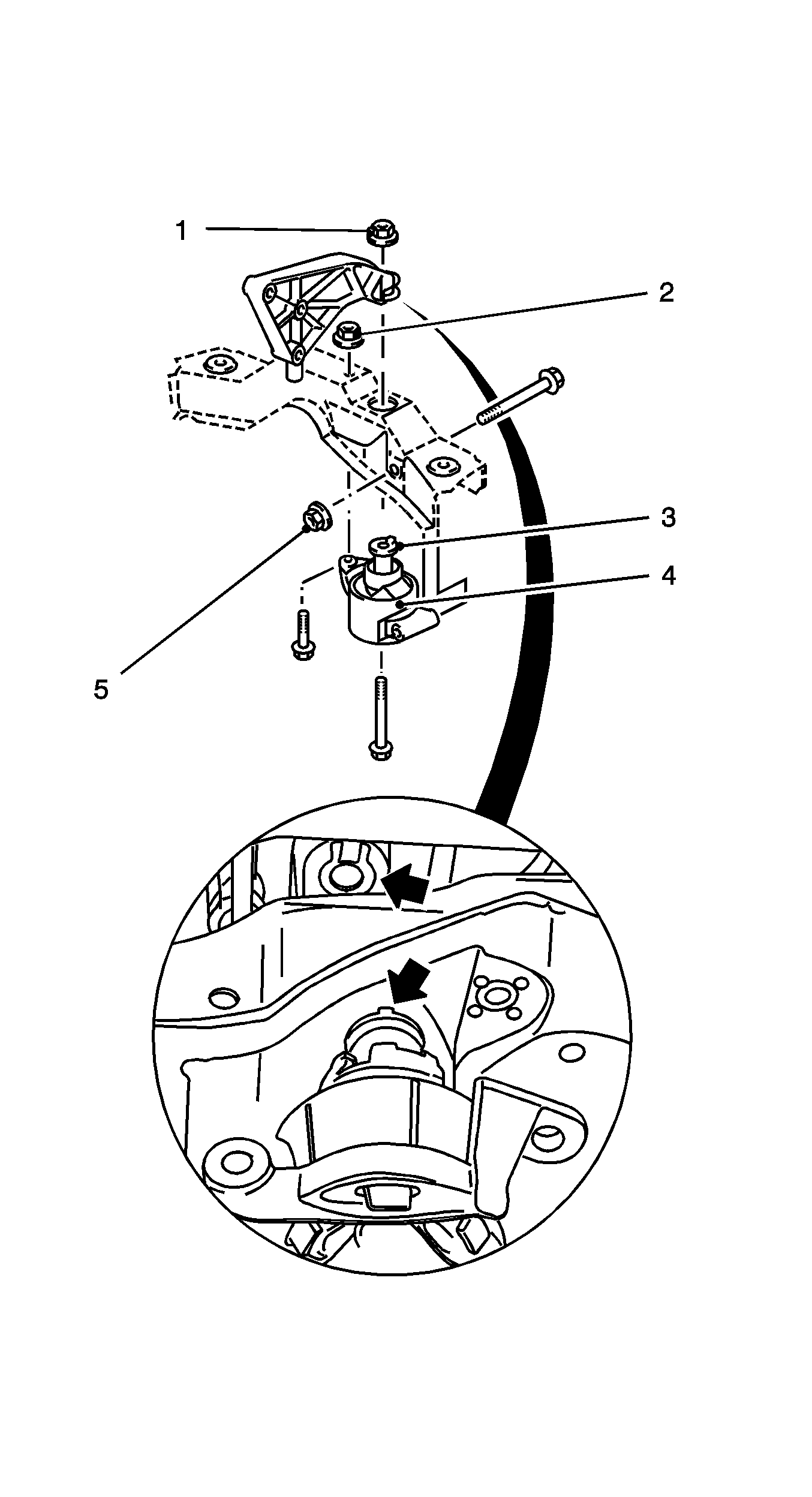
Note: Ensure that the positioning is perfect - the pin (3) must sit fully in the groove.
- Attach the bracket for rear engine damping block to engine damping block.
Use the new nut (1).
Tighten
Tighten to 55 N·m (40 lb ft).
- Attach the stabilizer to the front frame. Refer to
Stabilizer Shaft Replacement.
- Attach the 2 radiator brackets to front frame.
Tighten
Tighten to 15 N·m (11 lb ft).
- Install the front frame. Refer to
Front Frame Replacement.
Note: Vehicle must be standing on wheels, inspection stand or pit.
- Install the 2 bolted connections, control arm to the front frame.
Tighten
Tighten the 2 new screw connections for control arm on front frame to 90 N·m (67 lb ft) plus 75 degree, plus 15 degrees.
- Tighten control arm to frame bolt at trim height. Refer to
Trim Height Specifications.
- Perform the chassis alignment. Refer to
Alignment Checking.
- Fill and bleed the hydraulic system. Refer to
Hydraulic Brake System Bleeding.


