Removal Procedure
- Recover the refrigerant. Refer to
Refrigerant Recovery and Recharging.
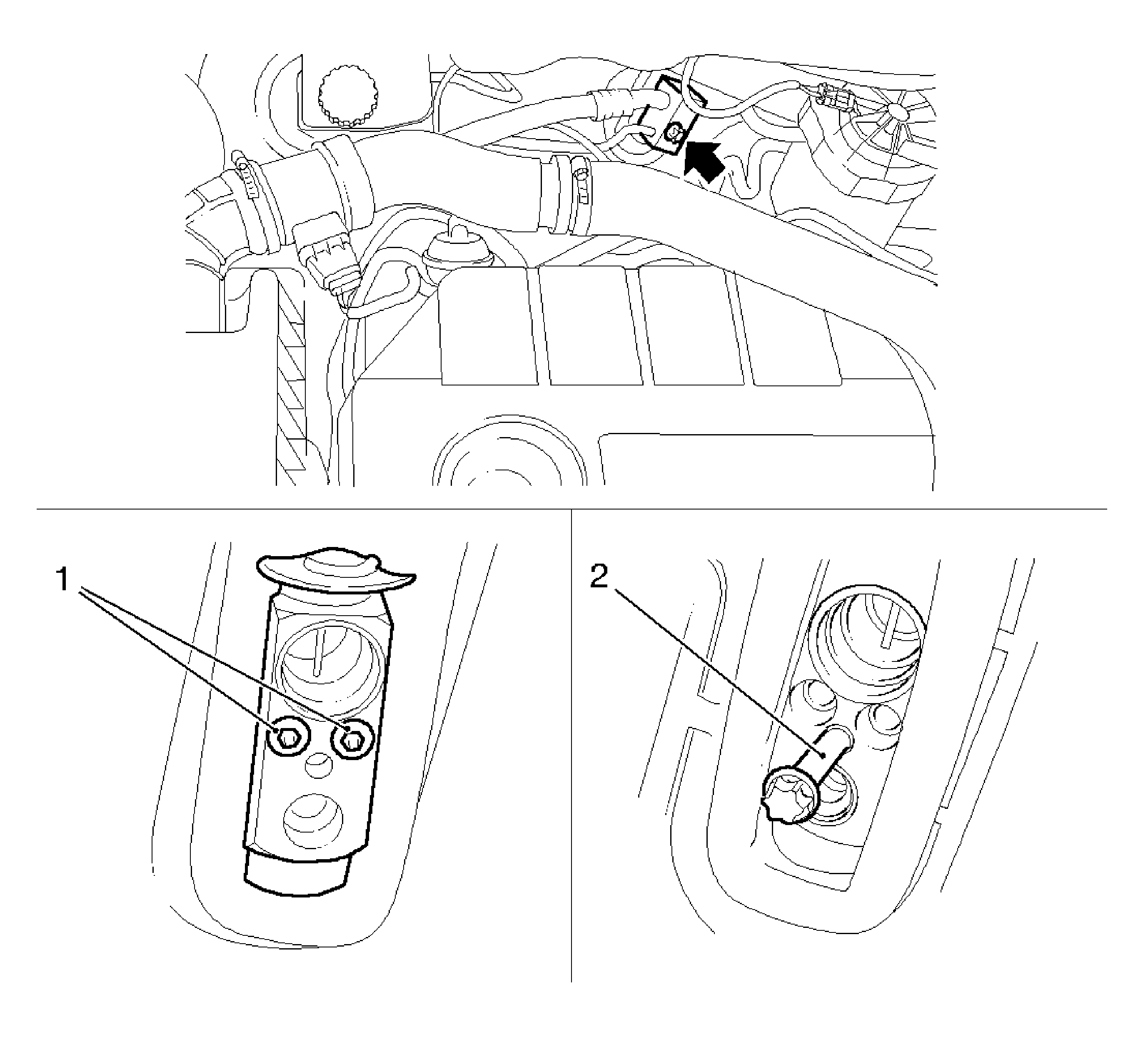
- Remove the block connector and refrigerant lines from the expansion valve.
| 2.2. | Disconnect the refrigerant lines. |
Note: If installation is postponed, close off lines and connections.
- Remove the thermostatically controlled expansion valve (TXV) (1).
Insert the bolt, block connector refrigerant line, in expansion valve (2) and remove the expansion valve.
- Remove the expansion valve retaining plate.
- Remove the air inlet screen. Refer to
Air Inlet Screen Replacement.
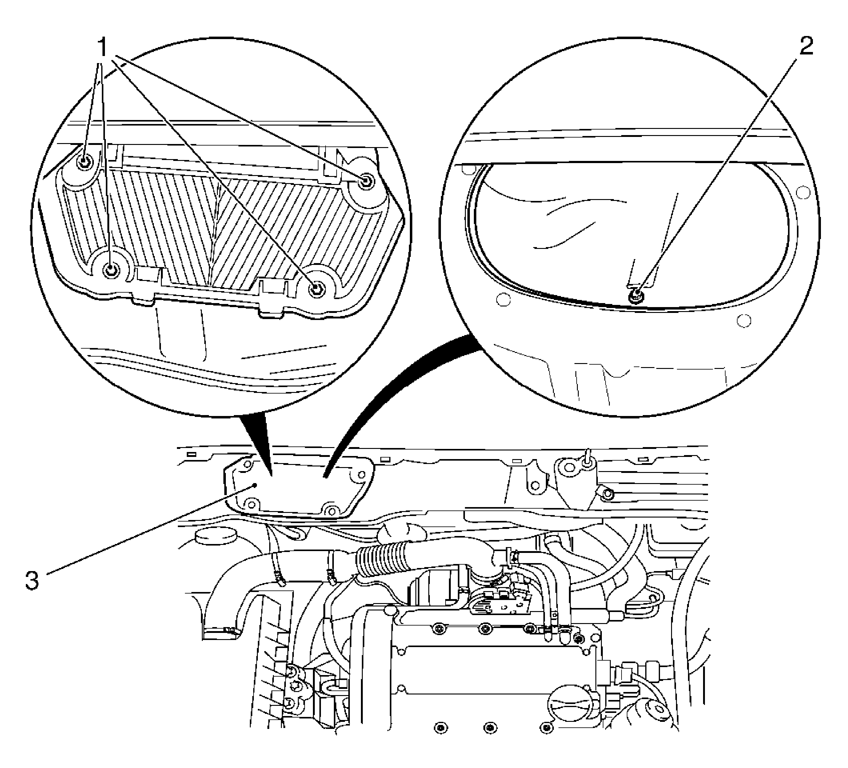
- Remove the recirculating air valve housing, outside.
| 6.1. | Remove the 4 bolts (1). |
| 6.2. | Remove the recirculating air valve housing grille (3). |
| 6.3. | Remove the bolt for recirculating air valve housing (2). |
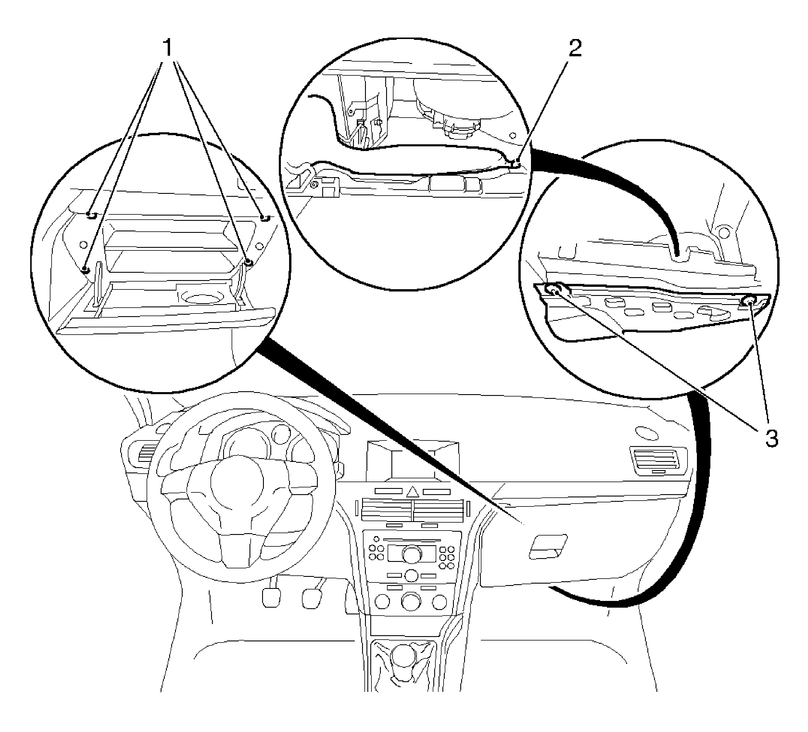
- Remove the instrument panel (I/P) compartment.
| 7.1. | Remove the 4 bolts (1). |
| 7.2. | Disconnect the wiring harness plug. |
- Remove the insulator panel.
Remove the 2 retainers (3).
- Remove the air duct.
Remove the body-bound rivet (2).
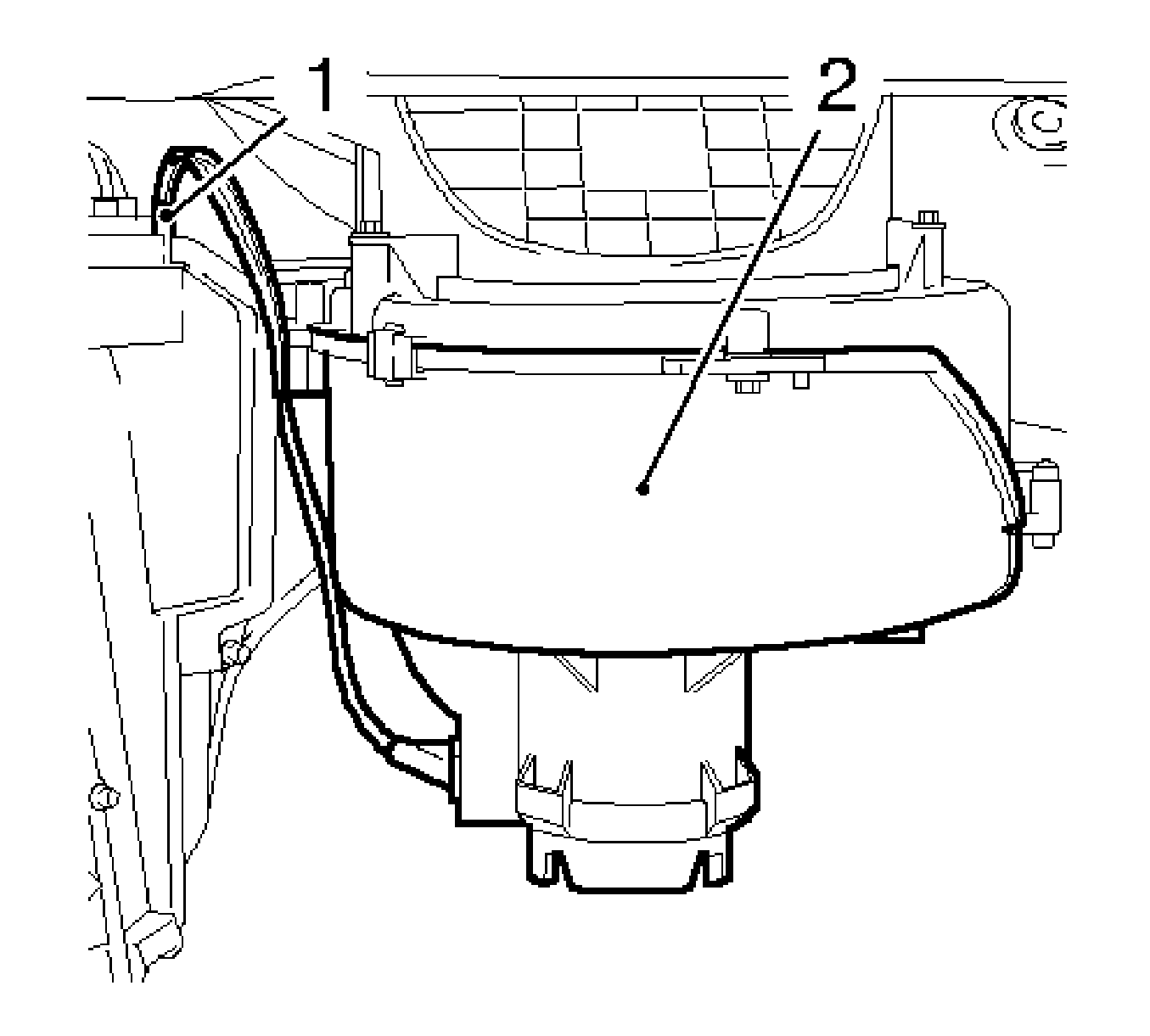
- Remove the heater fan motor (2).
| 10.1. | Disconnect the 2 wiring harness plugs (1) from the series resistor. |
| 10.3. | Remove the 5 bolts. |
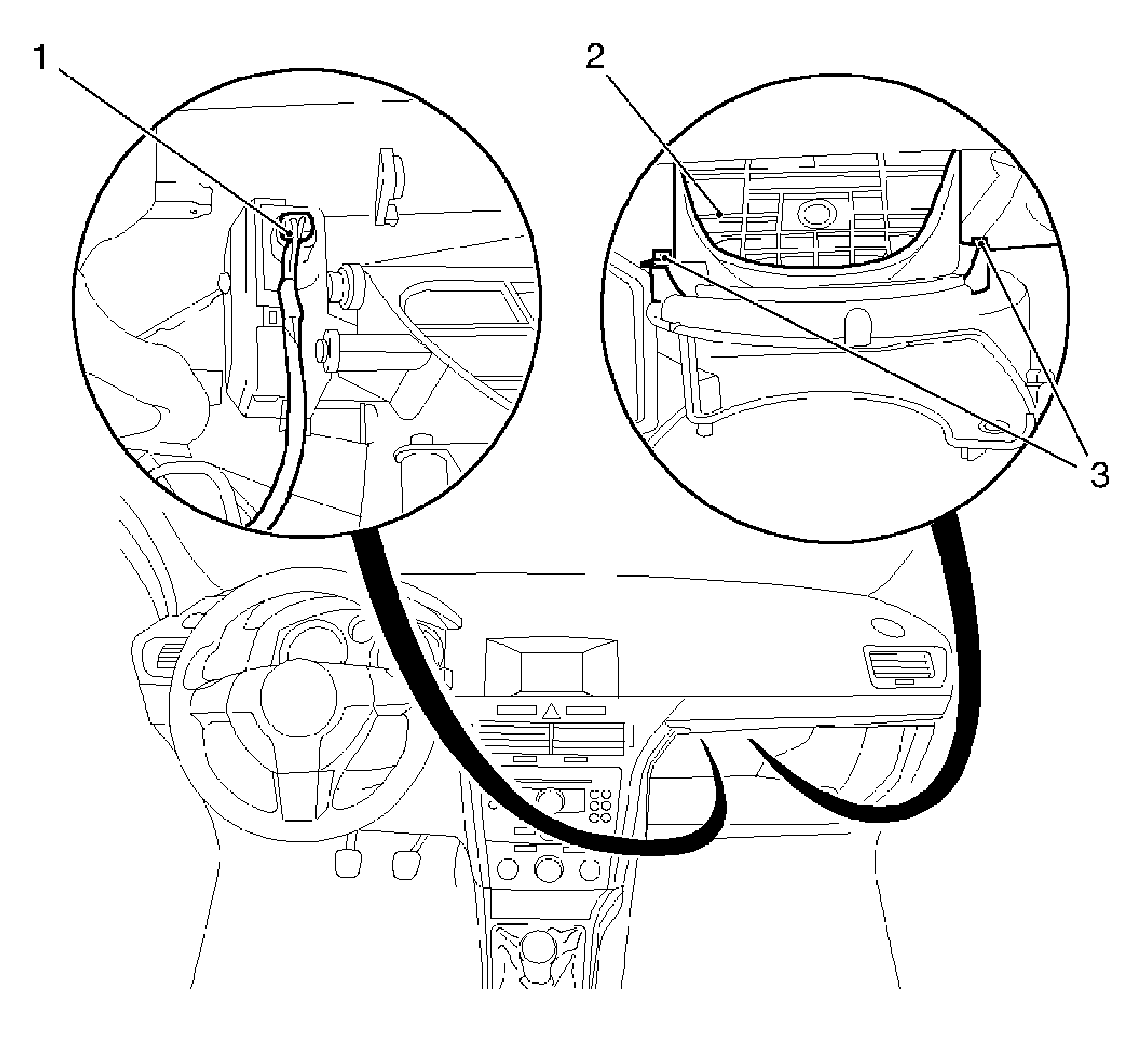
- Detach and remove the recirculating air valve housing (2).
| 11.1. | Remove the 2 bolts (3). |
| 11.2. | Disconnect the wiring harness plug for mixed air valve servo motor. |
| 11.3. | Release and disconnect the wiring harness plug. |
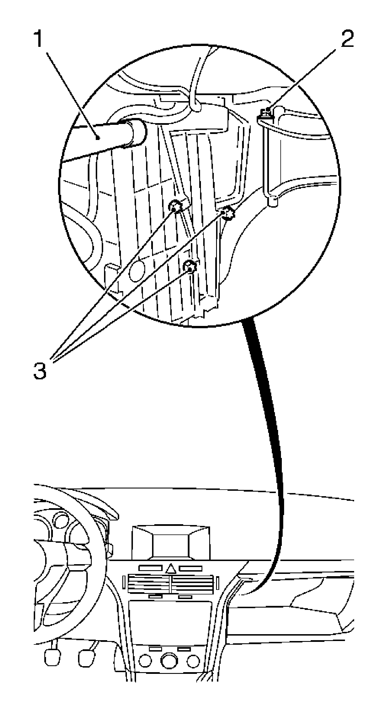
- Remove the bolt for recirculating air valve housing
Remove the bolt (2).
- Remove the pollen filter service flap and pollen filter.
Remove the 3 bolts (3).
Note: Only for vehicles with radio cooling.
- Disconnect the radio cooling (1) and remove.
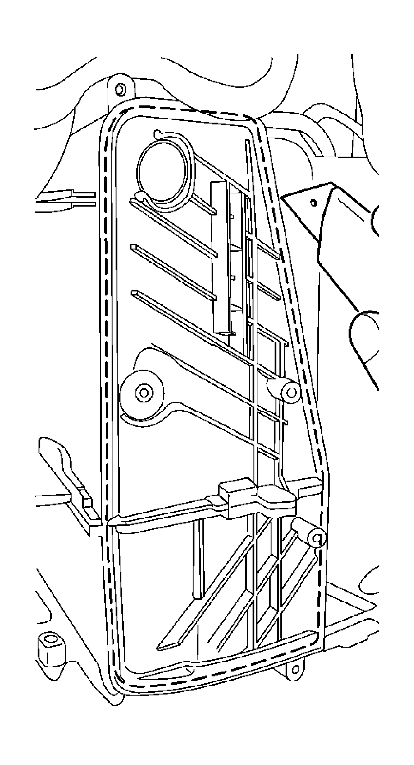
- Cut the air distributor housing.
Cut the air distributor housing at groove (dotted line) using a suitable tool.
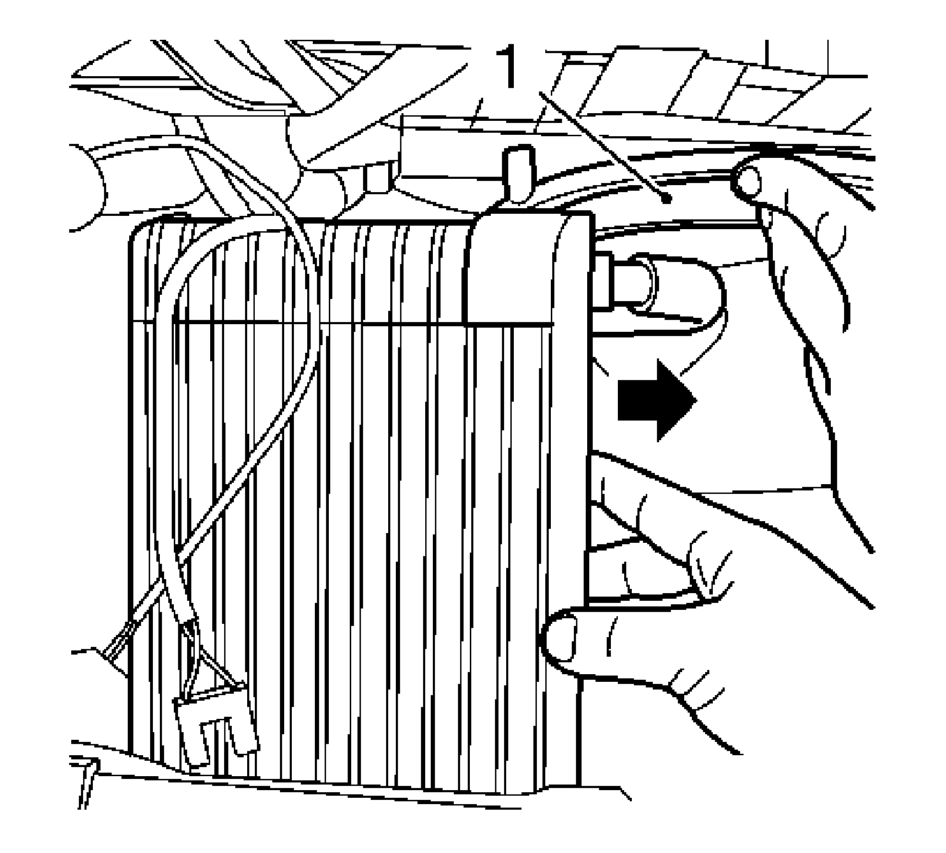
Note: Press the recirculating air valve housing upwards.
- Remove the evaporator core.
Installation Procedure
- Insert the evaporator core.
- Position the seal in the evaporator cover.
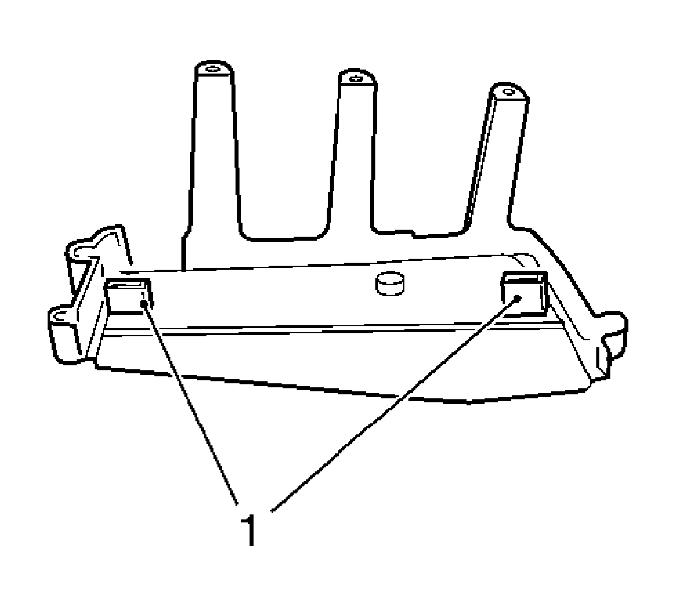
- Prepare the evaporator cover.
Cut the 2 plastic webs (1) using a suitable tool.
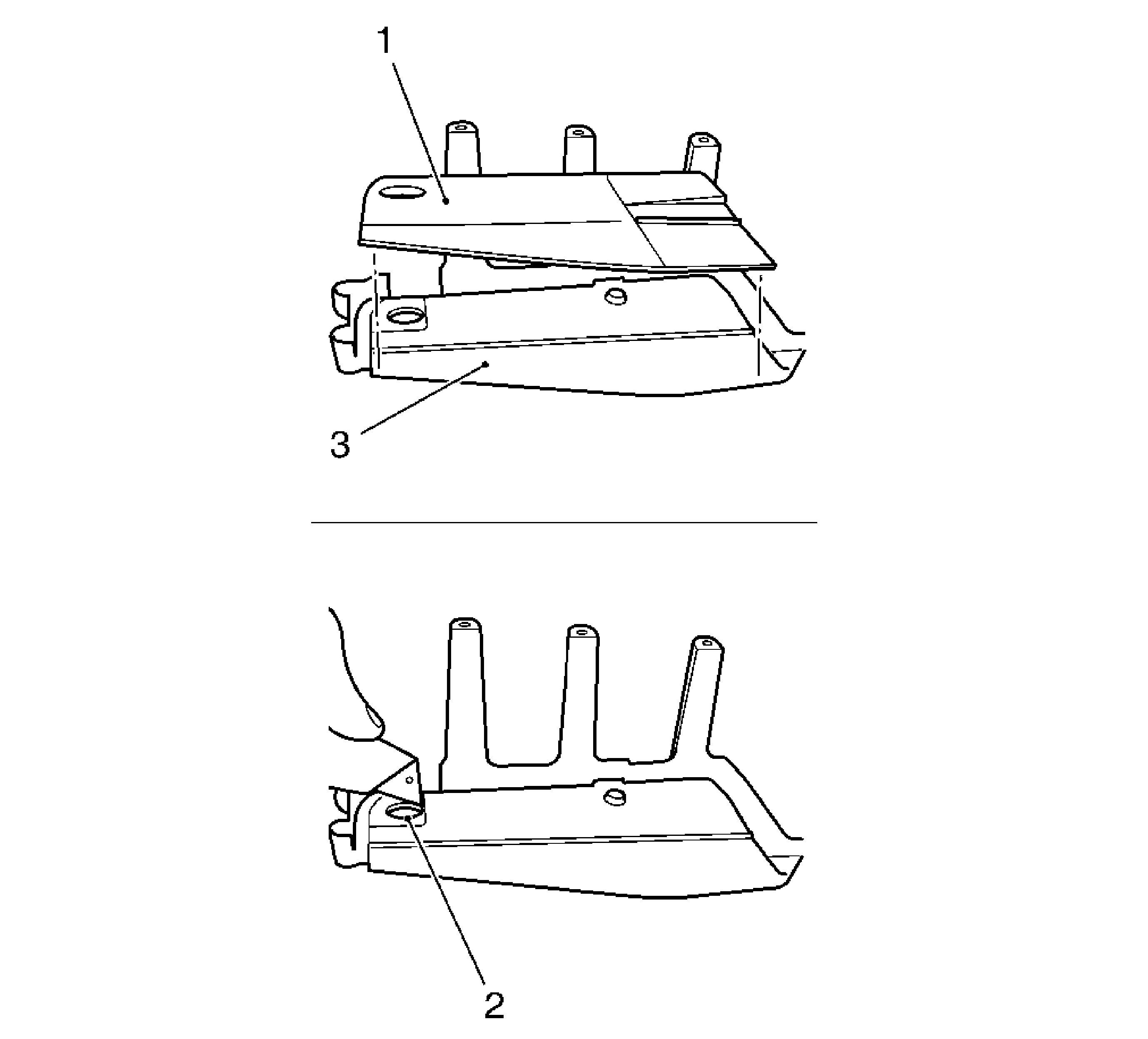
Note: Only for vehicles with radio cooling.
- Connect the radio cooling to evaporator cover.
| 4.1. | Place the cut evaporator cover (1) on new cover (3), and use a pencil to mark the hole for radio cooling. |
| 4.2. | Using a suitable tool, cut a hole (2) for radio cooling. |
| 4.3. | Glue the radio cooling in place on both sides. |
| 4.4. | Use adhesive mastic. |
Caution: Refer to Fastener Caution in the Preface section.
- Attach the evaporator cover.
Install the radio cooling.
Tighten
Tighten the 4 bolts to 2.5 N·m (22 lb in).
- Insert the pollen filter and attach pollen filter cover.
Tighten
Tighten the 3 bolts to 2.5 N·m (22 lb in).
- Install the bolt for recirculating air valve housing.
- Insert and tighten the recirculating air valve housing.
Tighten
Tighten the 2 bolts to 5 N·m (44 lb in).
- Connect the wiring harness plug to recirculating air valve servo motor.
- Install the heater fan motor.
Tighten
Tighten the 5 bolts to 8 N·m (71 lb in).
| 10.2. | Connect the 2 wiring harness plug. |
- Install the retaining plate TXV.
- Install the air inlet screen. Refer to
Air Inlet Screen Replacement.
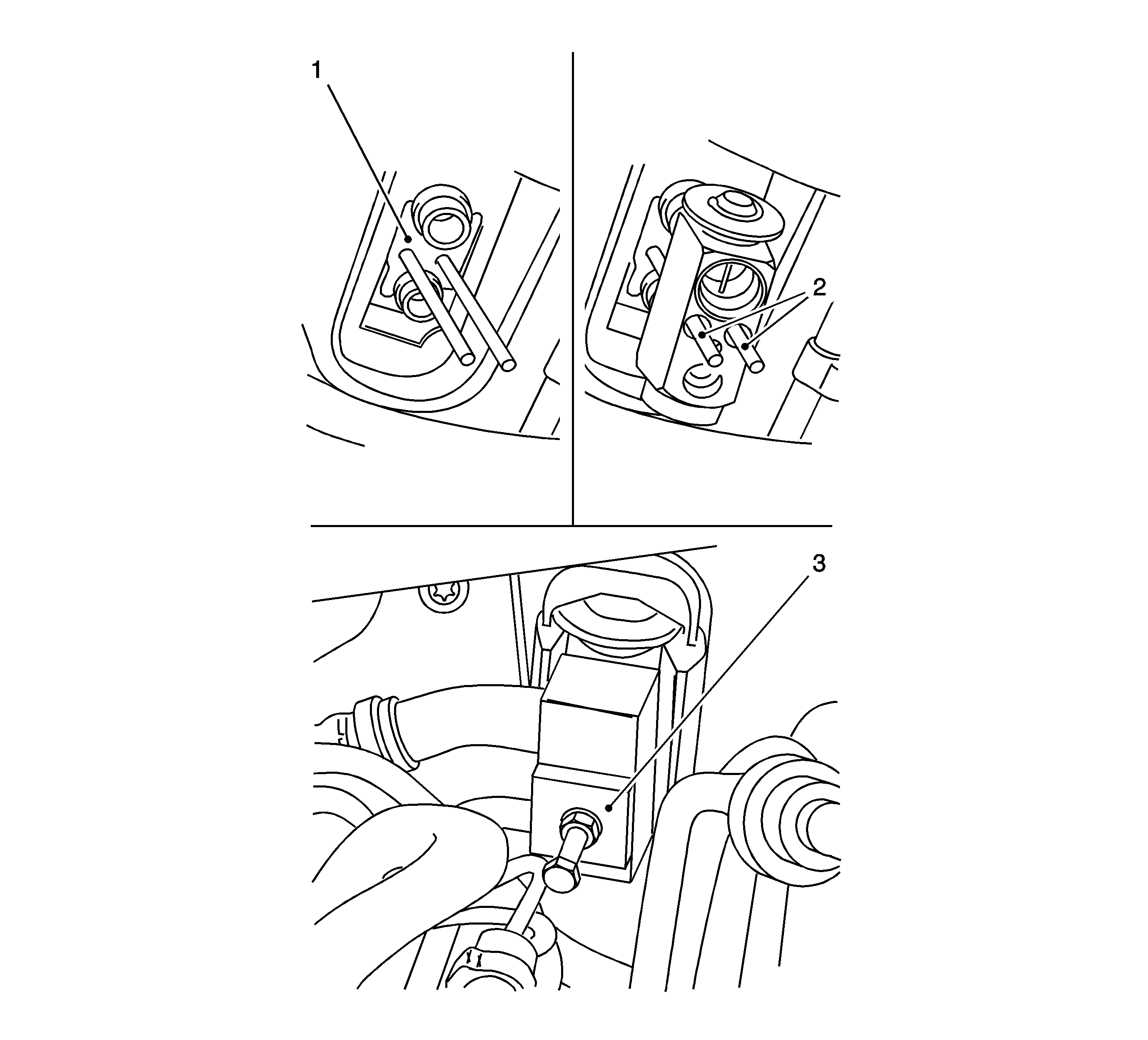
- Install the TXV.
| 13.1. | Use new sealing rings, before installation moisten only green colored sealing rings with mineral oil and insert. |
| 13.2. | Install service threaded rods (2) into retaining clip (1) to guide expansion valve. |
| 13.3. | Push expansion valve onto service threaded rods until the refrigerant lines lie in the expansion valve. |
| 13.4. | Replace the threaded rods in succession with the fixing bolts. |
Tighten
Tighten the expansion valve to 6 N·m (53 lb in).
- Install the block connector.
- Use new seal rings, before installation moisten only green colored seal rings with mineral oil and insert.
Tighten
Tighten the block connector bolt to 7 N·m (62 lb in).
- Install the air duct for footwell right side.
Connect the clip.
- Install the I/P compartment.
- Connect the wiring harness plug.
Tighten
Tighten the 4 bolts to 4 N·m (35 lb in).
- Install the insulator panel.
Tighten the 2 retainers.
- Recharge the A/C system. Refer to
Refrigerant Recovery and Recharging.


