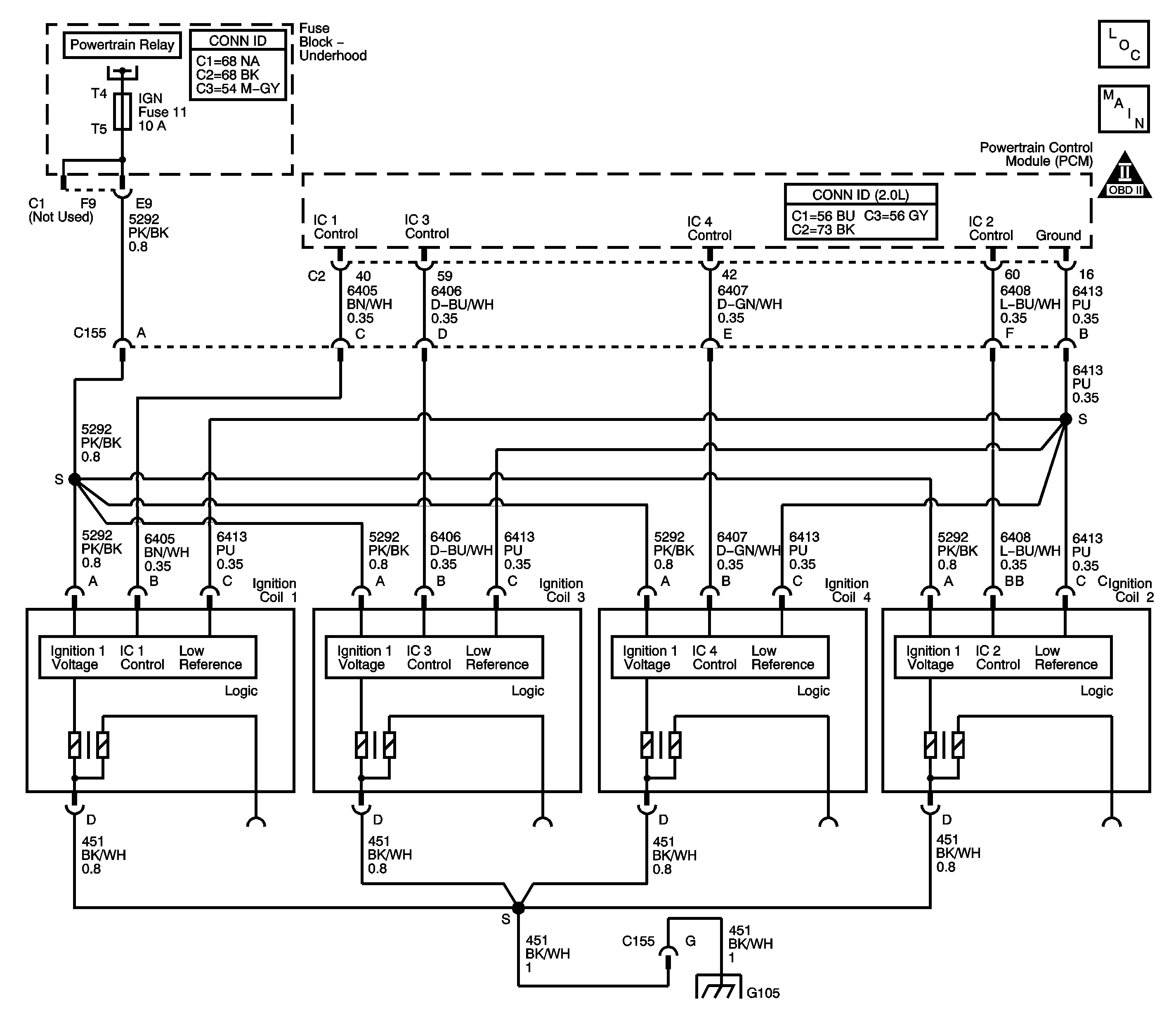
Circuit Description
Each ignition coil/module has the following circuits:
| • | An ignition voltage circuit |
| • | A ground |
| • | An ignition control (IC) circuit |
| • | A low reference circuit |
The PCM controls the individual coils by transmitting timing pulses on the IC circuit of each ignition coil/module to enable a spark event.
The spark plugs are connected to each coil by a short boot. The boot contains a spring that conducts the spark energy from the coil to the spark plug. The spark plug electrode is tipped with platinum for long wear and higher efficiency.
Diagnostic Aids
Perform the spark plug inspection procedure before continuing with this diagnostic. Refer to Spark Plug Inspection .
Step | Action | Values | Yes | No |
|---|---|---|---|---|
Schematic Reference: Engine Controls Schematics Connector End View Reference: Powertrain Control Module Connector End Views or Engine Controls Connector End Views | ||||
1 | Did you perform the Diagnostic System Check - Engine Controls? | -- | Go to Step 2 | |
2 |
Is the fuse open? | -- | Go to Step 9 | Go to Step 3 |
3 |
Did you find and correct the condition? | -- | Go to Step 14 | Go to Step 4 |
4 |
Does the voltage measure within 0.5 volt of the specified value? | B+ | Go to Step 5 | Go to Step 10 |
5 |
Is the resistance less than the specified value? | 3 ohms | Go to Step 6 | Go to Step 11 |
6 |
Does the misfire follow the transferred ignition coil/module? | -- | Go to Step 12 | Go to Step 7 |
7 | Test the ignition control (IC) circuit of the affected ignition coil/module for the following conditions:
Refer to Circuit Testing and Wiring Repairs in Wiring Systems. Did you find and correct the condition? | -- | Go to Step 14 | Go to Step 8 |
8 | Test for an intermittent and for a poor connection at the powertrain control module (PCM). Refer to Testing for Intermittent Conditions and Poor Connections and Connector Repairs in Wiring Systems. Did you find and correct the condition? | -- | Go to Step 14 | Go to Step 13 |
9 | Repair the short to ground in the spliced circuits or the ignition coil/module, as needed. Refer to Testing for Short to Ground and Wiring Repairs in Wiring Systems. Did you complete the repair? | -- | Go to Step 14 | -- |
10 | Repair the high resistance or an open in the ignition voltage circuit of the affected ignition coil/module. Refer to Wiring Repairs in Wiring Systems. Did you complete the repair? | -- | Go to Step 14 | -- |
11 | Repair the high resistance or an open in the ground circuit of the affected ignition coil/module. Refer to Wiring Repairs in Wiring Systems. Did you complete the repair? | -- | Go to Step 14 | -- |
12 | Replace the ignition coil/module. Refer to Ignition Coil Replacement . Did you complete the replacement? | -- | Go to Step 14 | -- |
13 | Replace the PCM. Refer to Powertrain Control Module Replacement . Did you complete the replacement? | -- | Go to Step 14 | -- |
14 |
Does the vehicle operate normally? | -- | System OK | Go to Step 2 |
