GM Service Manual Online
For 1990-2009 cars only
Makes
🢒
Saturn
🢒
2007
🢒
ION
🢒
Diagnostic Navigation
🢒
Vehicle Diagnostic Information
🢒 Instrument Cluster Schematics
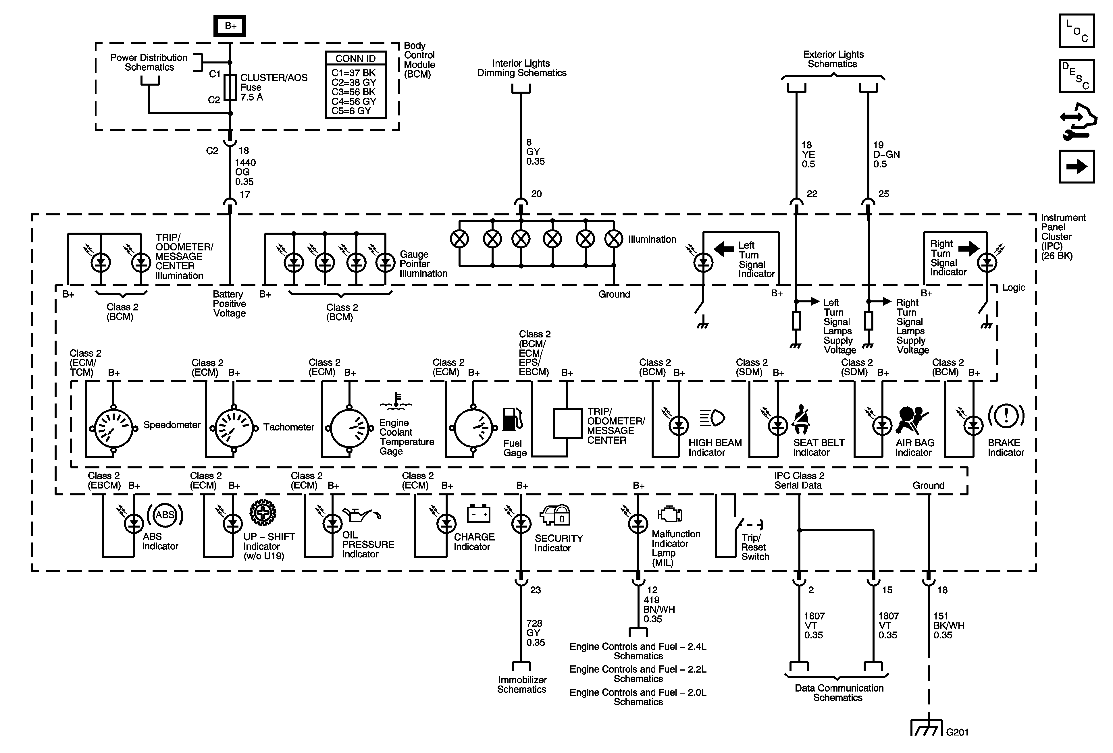
Figure
1:
DLC, Gages, Ground, Indicators, and Power
Master Electrical Component List
Instrument Cluster Description and Operation
Control Module References
Fuel Level and Oil Pressure
BCM, ELECT, CLUSTER/AOS, EPS (60A), FUEL PUMP, HVAC, IGN SW, IP BATT 2, RUN (IGN3), and STOP Fuses, RUN and Fuel Pump Relays
Turn Signal/Multifunction Switch, Instrument Panel Cluster, I/P Dimmer Switch, Hazard Switch, Fog Lamp Switch, Traction Control Switch, and Radio
Turn/Hazard Lamps
Vehicle Theft Deterrent
Power, Ground, MIL, and Serial Data
Power, Ground, Class 2, and Low Speed GMLAN
G201
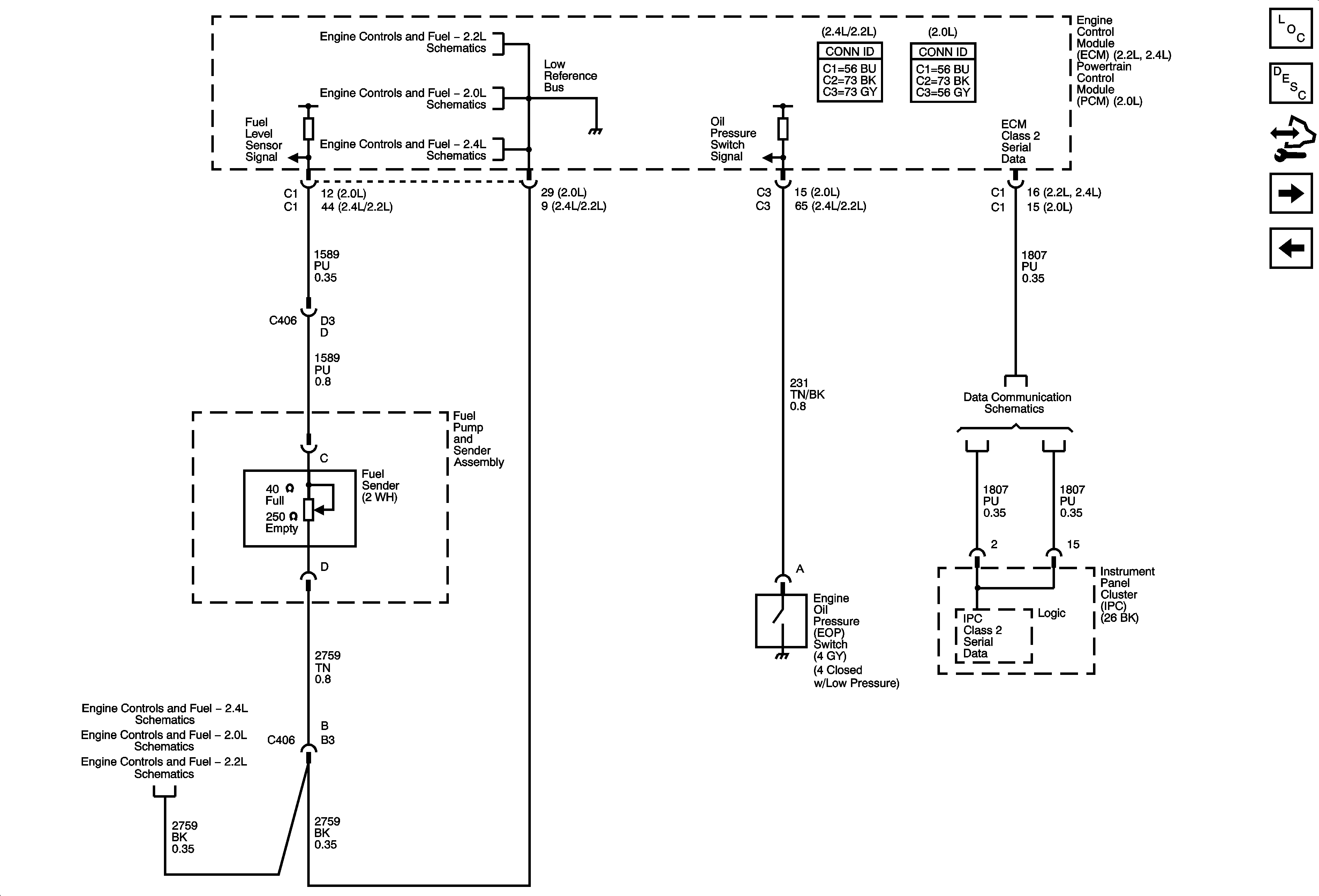
Figure
2:
Fuel Level and Oil Pressure
Master Electrical Component List
Instrument Cluster Description and Operation
Control Module References
Boost Gage - UXE
DLC, Gages, Ground, Indicators, and Power
Engine Data Sensors - 5-Volt and Low Reference
Engine Data Sensors - 5-Volt and Low References
Power, Ground, Class 2, and Low Speed GMLAN
Engine Data Sensors - 5-Volt and Low References
Engine Data Sensors - 5-Volt and Low Reference
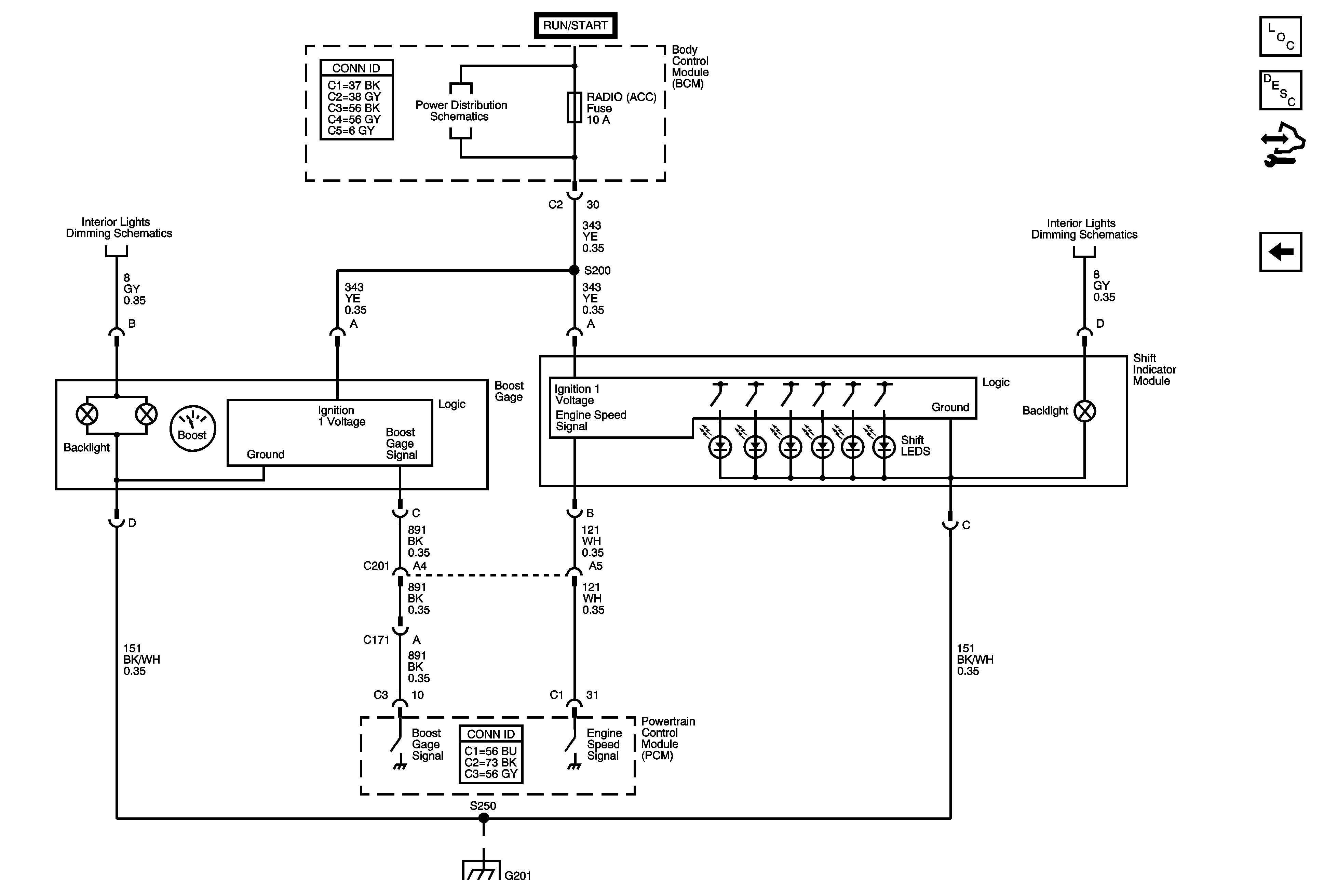
Figure
3:
Boost Gage - UXE
Master Electrical Component List
Instrument Cluster Description and Operation
Control Module References
Fuel Level and Oil Pressure
BCM (PWR), DASH, IP BATT 1, IP BATT 1A, LIGHTER, ONSTAR, PARK PWR OUTLET, PWR WINDOWS, RADIO (BATT 1), RADIO (ACCY), SUNROOF, and WIPER SW Fuses
Shift Indicator Module, Boost Gage, A/T Shift Indicator, and HVAC Control Assembly
G201