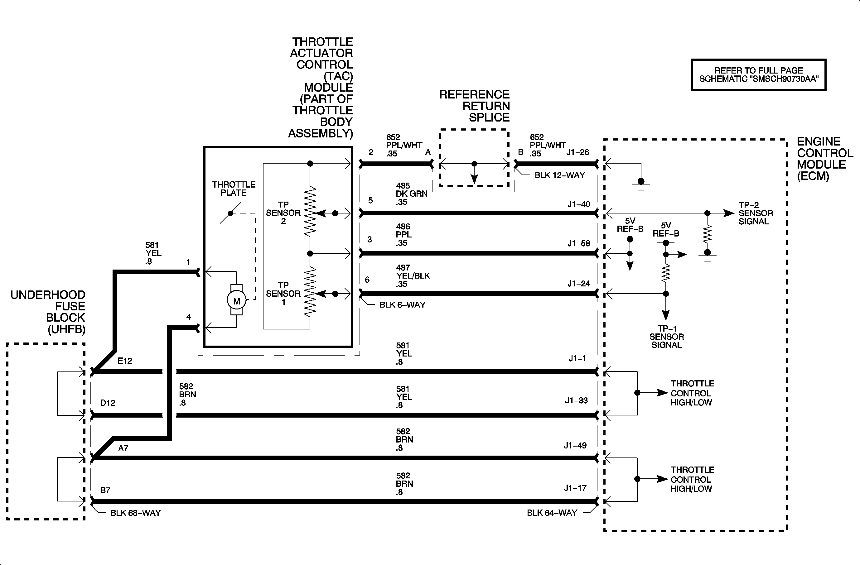
Circuit Description
The throttle actuator control (TAC) module contains a direct current actuator motor controlled by the engine control module (ECM) used to move the throttle plate, in either direction, and 2 throttle position sensors to determine the throttle plate position. The throttle plate is held at a 7 percent rest position to a mechanical stop by a constant force return spring. This spring will hold the throttle plate to the stop when there is no current flowing to the actuator motor. There is another return spring, which creates constant force on the throttle plate only when the throttle plate is moved towards the full closed position. The ECM will monitor both the actuator motor and TP sensors for circuit faults as well as check to make sure both springs can return the throttle to the 7 percent position no matter where the throttle plate remains. DTC P1516 will set if the commanded throttle plate position, based on the actuator motor pulse width differs greater than a calibrated amount from the actual throttle plate position, based on the TP sensors for a certain length of time, OR if a throttle actuator motor circuit fault occurs.
Conditions for Setting the DTC
DTC P1516 will set if the commanded throttle plate position, based on the actuator motor pulse width differs greater than a calibrated amount from the actual throttle plate position, based on the TP sensors.
A throttle actuator motor circuit fault occurs when the condition exists for longer than 0.5 seconds.
DTC P1516 diagnostic runs continuously with the ignition ON.
DTC P1516 is a type A DTC.
The malfunction indicator lamp (MIL) will only illuminate if the fault is present for longer than 5 seconds.
Diagnostic Aids
Important: If any TP sensor 1 or 2 DTC is set, diagnose that DTC first.
A short to ground or voltage on circuit 581 or 582 will set P1510 and P1516. An open in either, will set DTC P1516.
If DTC P1516 is set, the ECM will default to 1 of the 2 limp home modes, random injector disable with engine speed limited to 1800 RPM. The REDUCED POWER telltale will be illuminated and the ECM will remain in this condition for the entire ignition cycle even if the fault is corrected.
To locate an intermittent problem, use the scan tool to monitor DTC P1516 LAST TEST with the engine running while accelerating the engine up and down the RPM band. Watching for a change from PASSED to FAILED indicates a circuit fault or throttle plate restriction is occurring.
Test Description
The numbers below refer to the step numbers on the diagnostic table.
-
The throttle valves are spring loaded in a slightly open position and should move in either direction without binding. The throttle valves should always be under spring pressure.
-
When the ignition is turned ON, the ECM operates the throttle control motor to verify the integrity of the system prior to start-up. This can be seen by the momentary flash of the test lamp as the ignition is turned ON.
Step | Action | Value | Yes | No | ||||||
|---|---|---|---|---|---|---|---|---|---|---|
Schematic Reference: Engine Controls Schematics Connector End View Reference: Powertrain Control Module Connector End Views | ||||||||||
1 | Observe the DTC information. Are DTCs P0121, P0122, P0123, P0221, P0222, P0223 also set? | -- | Go to Step 2 | |||||||
Did you find any of the above conditions with the throttle body? | -- | Go to Step 10 | Go to Step 3 | |||||||
3 |
Important: Disconnecting the throttle body connector will cause additional codes to set.
Is the voltage within the specified range for both circuits? | 2-4 V | Go to Step 5 | Go to Step 4 | ||||||
4 | Is the voltage less than the specified value? | 2 V | Go to Step 7 | Go to Step 6 | ||||||
Does the test lamp flash ON, then turn OFF? | -- | Go to Step 8 | Go to Step 9 | |||||||
6 | Test the TAC motor control circuit that measured above the specified value for a short to voltage. Refer to Wiring Repairs in Wiring Systems. Did you find and correct the condition? | -- | Go to Step 12 | Go to Step 11 | ||||||
7 | Test the TAC motor control circuit that measured below the specified value for a short to ground. Refer to Wiring Repairs in Wiring Systems. Did you find and correct the condition? | -- | Go to Step 12 | Go to Step 11 | ||||||
8 | Test for a poor connection or terminal tension at the throttle body connector. Did you find and correct the condition? | -- | Go to Step 12 | Go to Step 10 | ||||||
9 | Test for a poor connection or terminal tension at the engine control module (ECM). Did you find and correct the condition? | -- | Go to Step 12 | Go to Step 11 | ||||||
10 | Replace the throttle body assembly. Refer to Throttle Body Assembly Replacement . Did you complete the replacement? | -- | Go to Step 12 | -- | ||||||
11 | Replace the ECM. Refer to Engine Control Module Replacement . Did you complete the replacement? | -- | Go to Step 12 | -- | ||||||
12 |
Did the DTC fail this ignition? | -- | Go to Step 1 | Go to Step 13 | ||||||
13 | Observe the Capture Info with a scan tool. Does the scan tool display any DTCs that you have not diagnosed? | -- | System OK | |||||||
