Removal Procedure
- Remove the transaxle case side cover. Refer to Control Valve Body Cover Replacement .
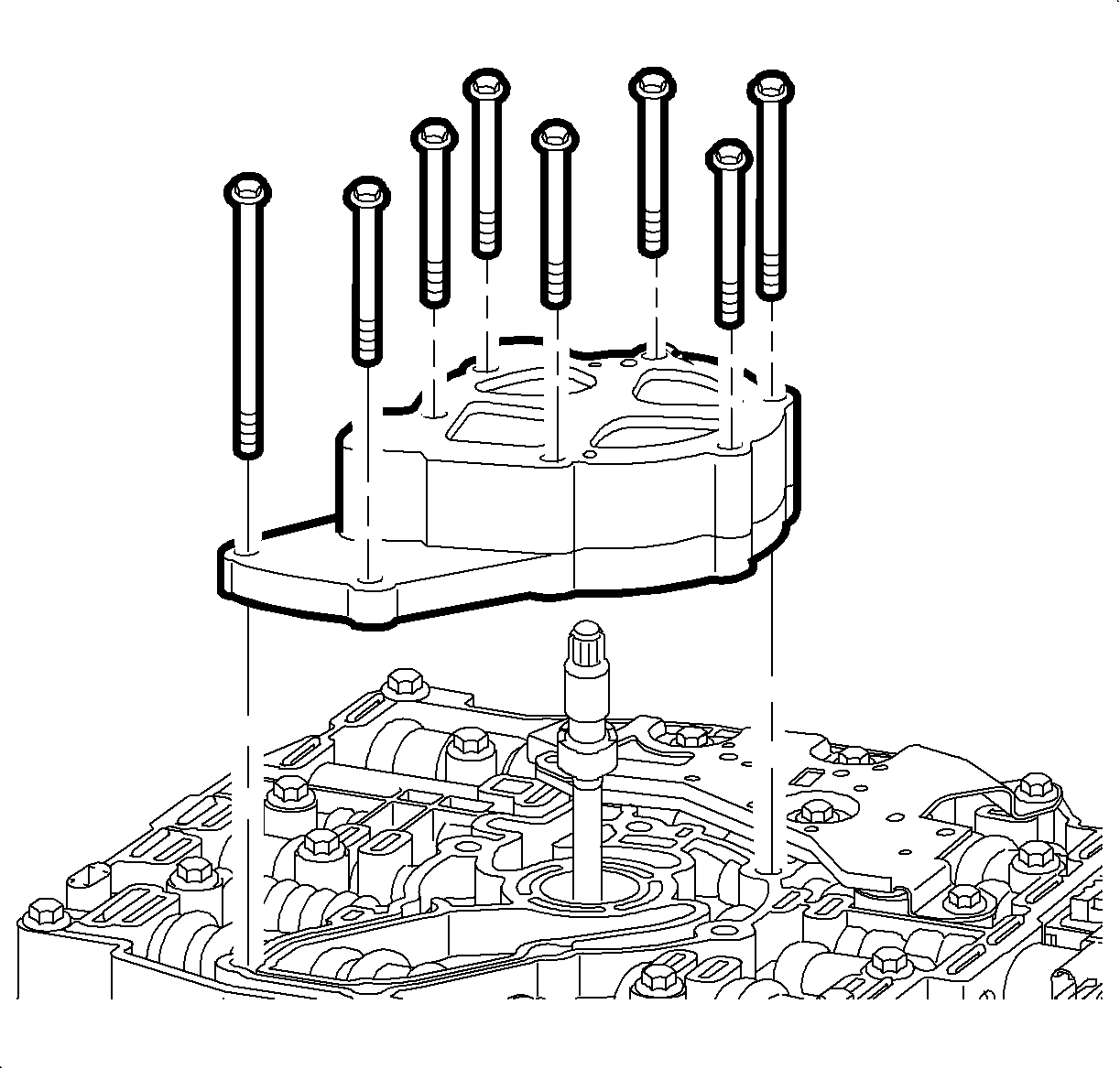
- Remove the oil pump bolts and the oil pump assembly.
- Remove the oil pump shaft.
- Disconnect the wire harness connectors from the following components:
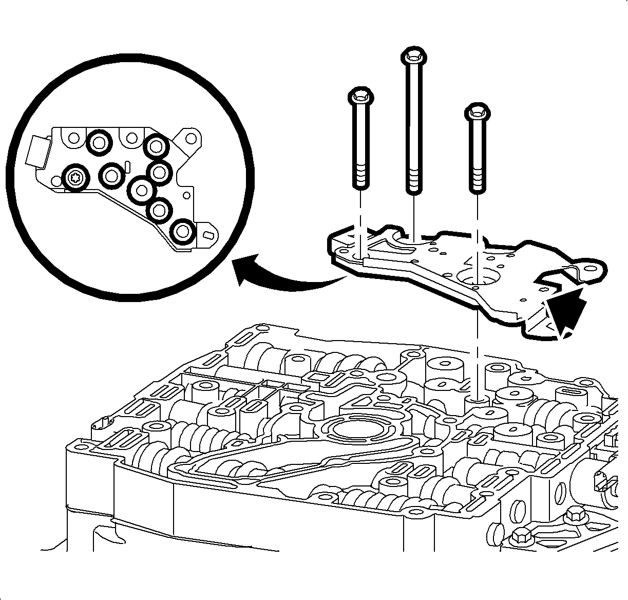
- Remove the TFP switch assembly bolts and remove the switch assembly from the control valve body. The 7 TFP switch O-rings are reusable if not damaged and should remain with the pressure switch assembly.
- Remove the remaining control valve body bolts and remove the control valve body assembly.
- Remove and discard the valve body-to-spacer plate gasket.
- Remove the spacer plate support bolts and remove the spacer plate support.
- Remove the spacer plate with the spacer plate filter attached.
- Remove and discard the spacer plate-to-channel plate gasket.
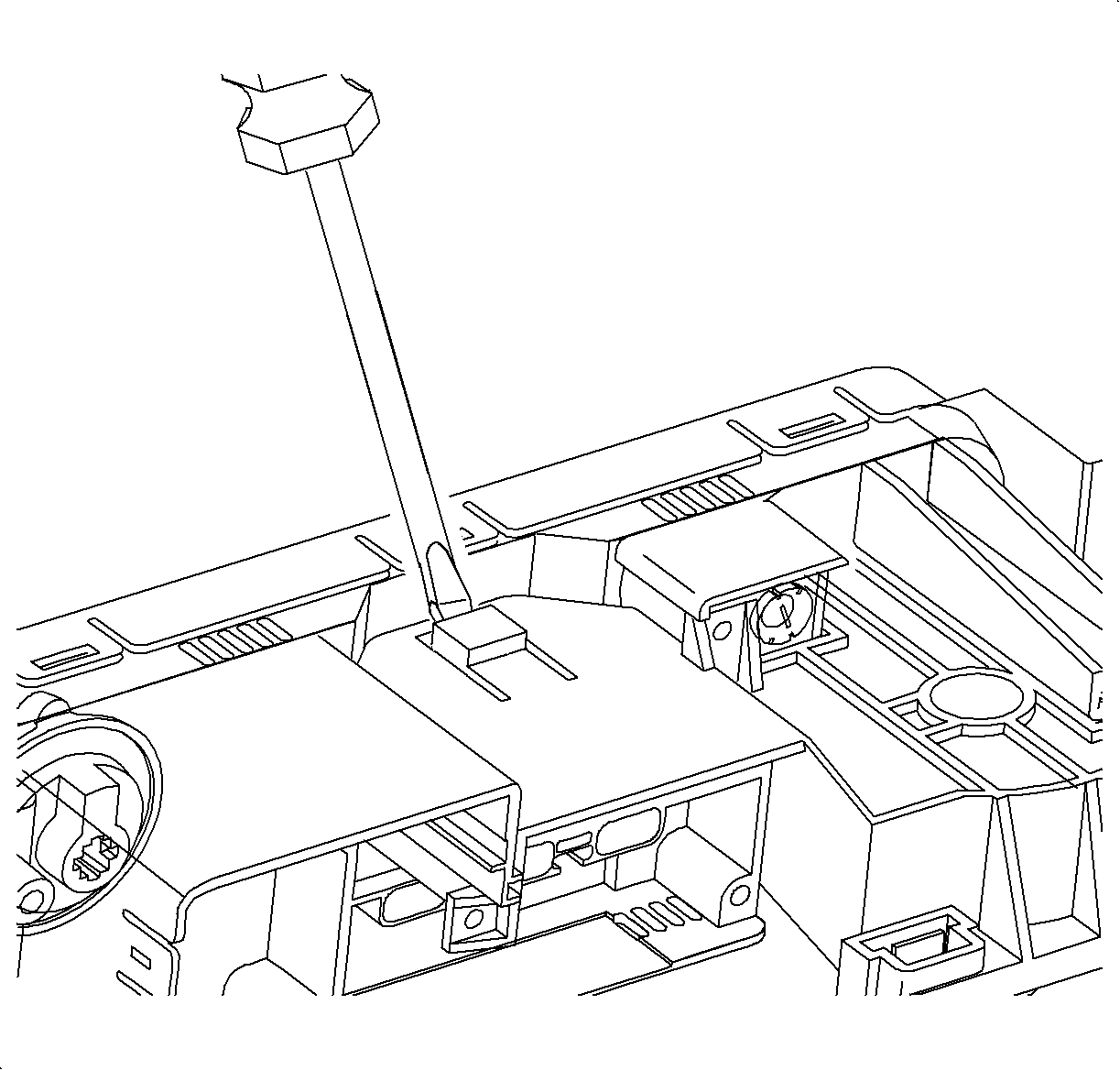
| • | Pressure control solenoid |
| • | 1-2, 2-3 shift solenoids |
| • | TFP switch assembly |
| • | TCC solenoid |
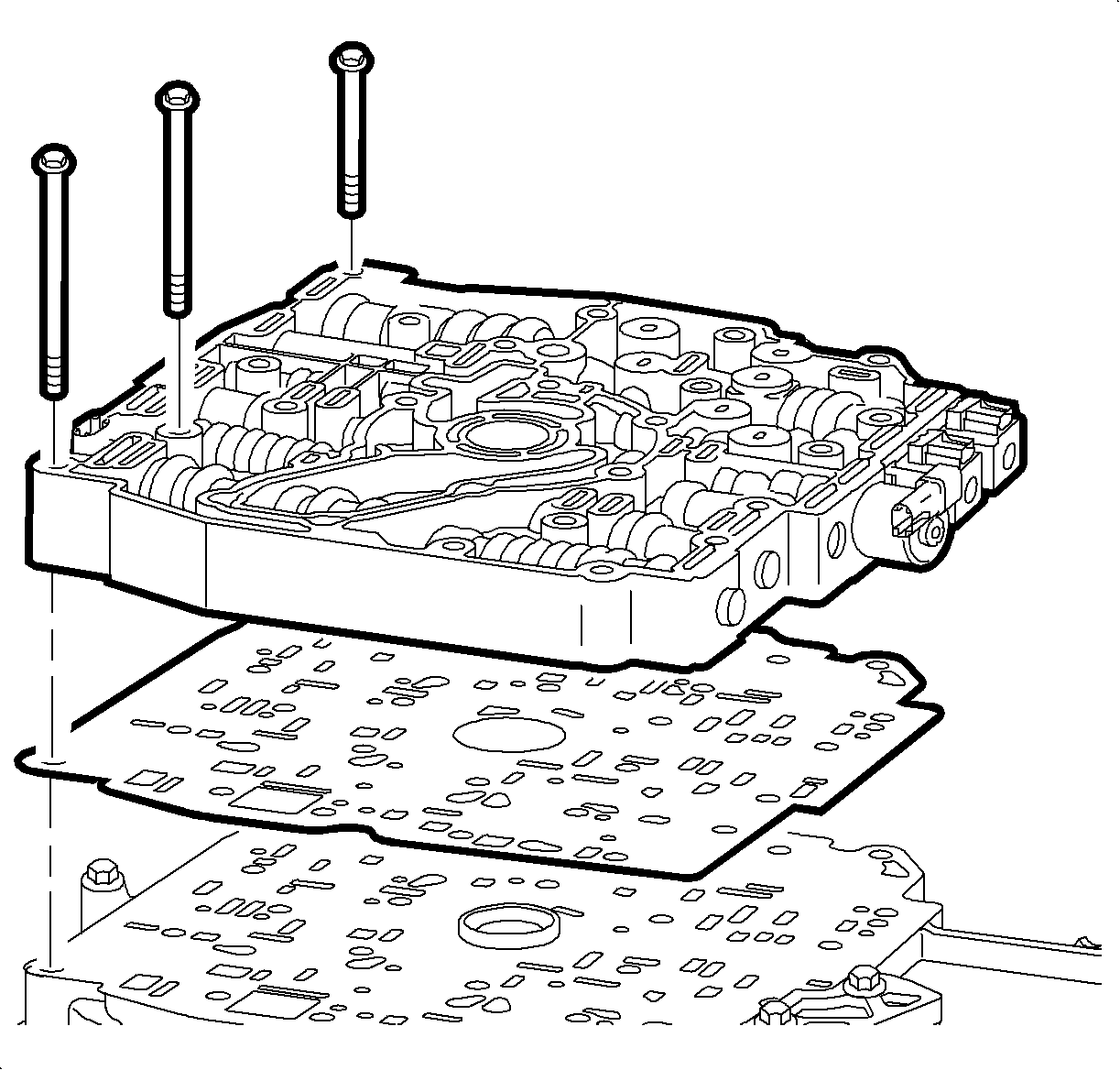
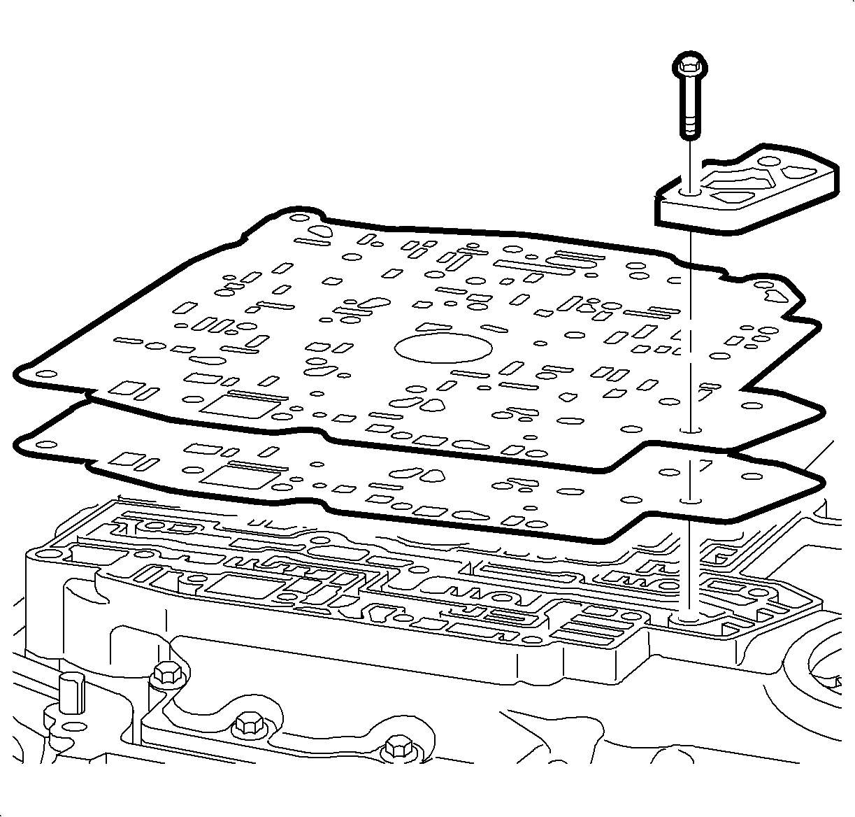
Important: Checkballs may fall out of the channel plate assembly. Retain the checkballs with petroleum jelly.
Disassembly/Assembly Procedure
For step by step instructions on how to disassemble/assemble the control valve body, refer to Control Valve Body Disassemble and Control Valve Body Assemble .
Installation Procedure
- Make sure the checkballs are in the proper locations on the channel plate. Retain the checkballs with petroleum jelly.
- Install a new spacer plate-to-channel plate gasket onto the channel plate.
- Install the spacer plate with the spacer plate filter attached.
- Hand start the spacer plate support bolts and install the spacer plate support.
- Install a new control valve body to the spacer plate gasket onto the spacer plate.
- Install the control valve body assembly onto the gasket. Hand start the control valve body assembly bolts to hold the valve body in place.
- Inspect the TFP switch assembly in order to verify the condition and the correct location of the pressure switch O-rings. If necessary, replace the TFP switch assembly O-rings.
- Install the TFP switch assembly onto the control valve body assembly.
- Install the remaining control valve body bolts.
- Hand start the bolts.
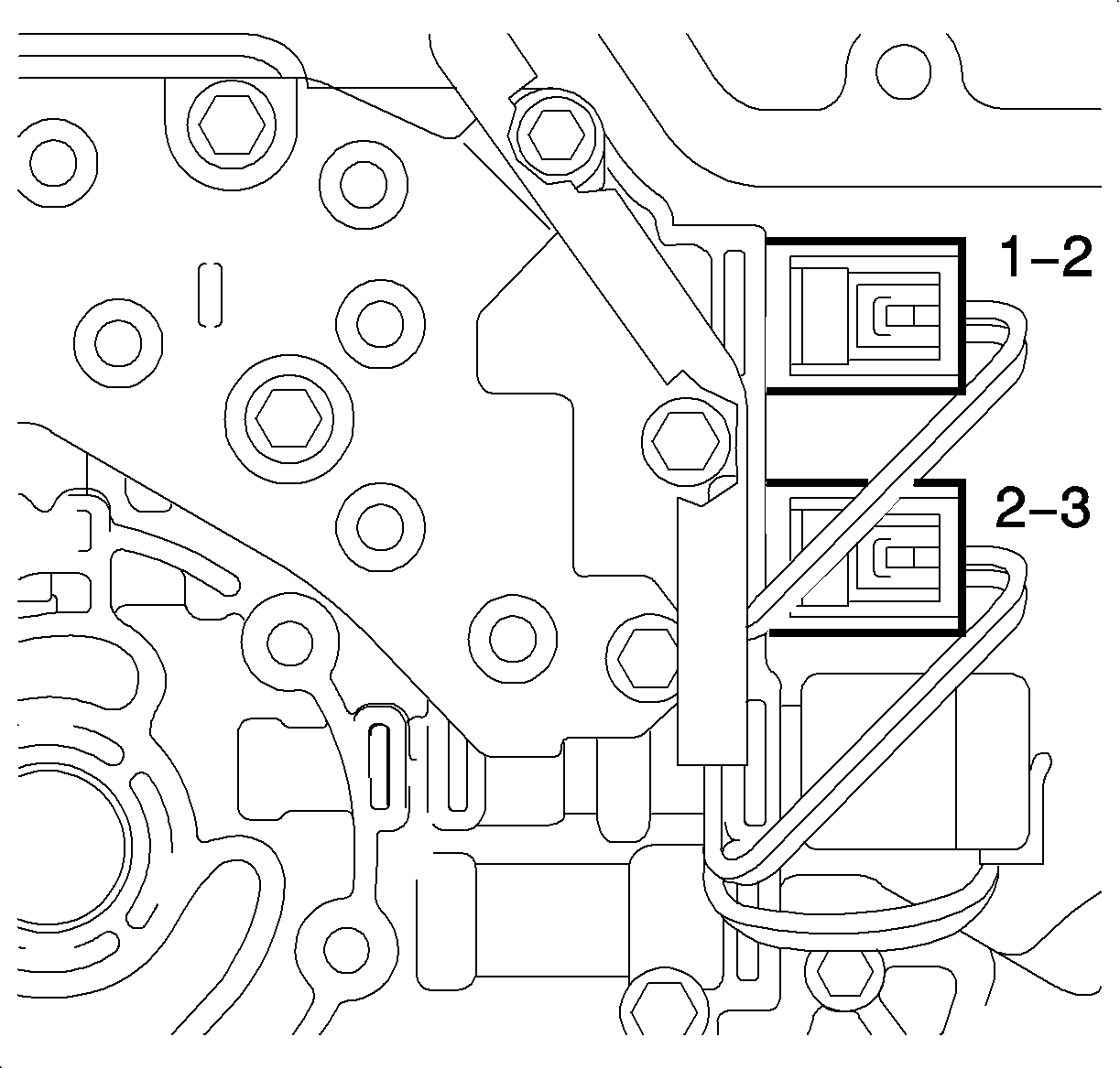
- Connect the transaxle wiring harness to the following components:
- Install the oil pump shaft into the control valve body assembly.
- Install the oil pump assembly onto the oil pump shaft and the control valve body. Hand start and install the oil pump assembly bolts.
- Install the transaxle case side cover. Refer to Control Valve Body Cover Replacement .
- Start the engine, warm up the transaxle, and check for leaks.
- Inspect for proper fluid level. Refer to Transmission Fluid Check .
- Reset the TAP values. Refer to Adapt Function .
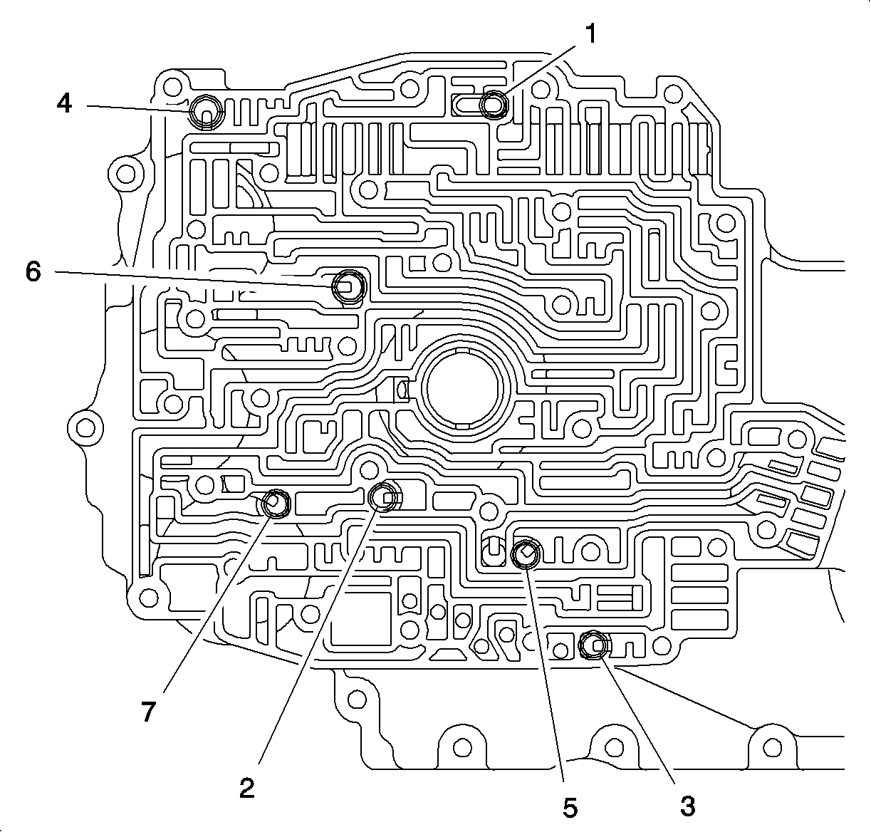

Notice: Refer to Fastener Notice in the Preface section.
Tighten
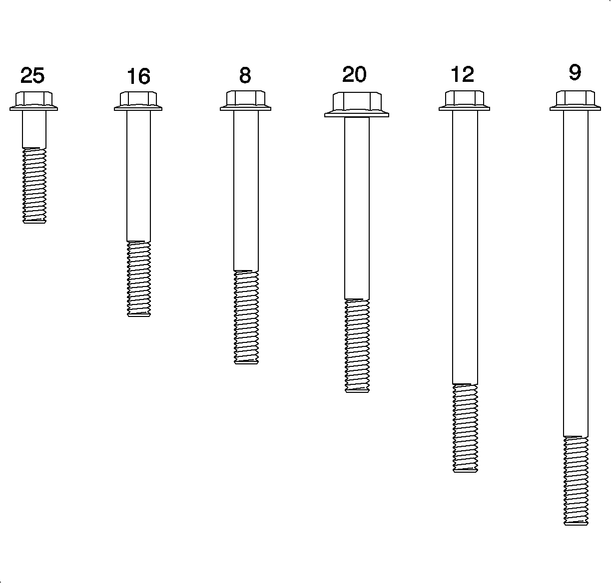
Tighten the spacer plate support bolts to 14 N·m (10 lb ft).

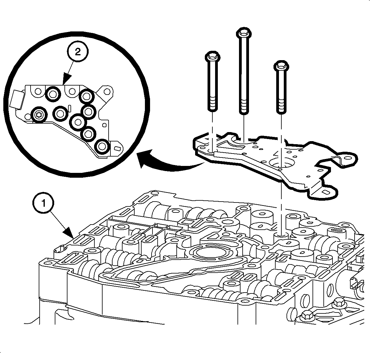
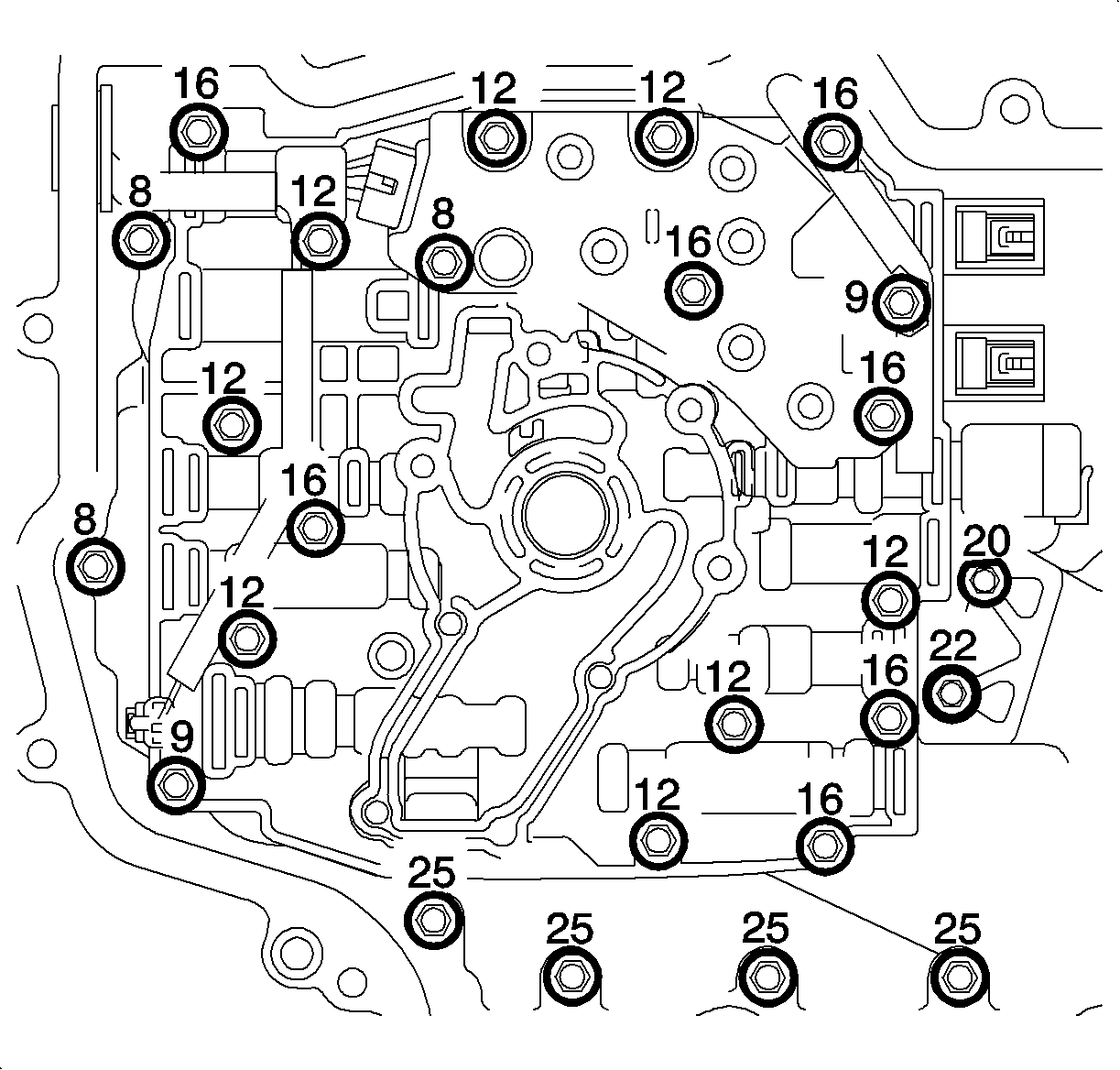
Tighten
Tighten the control valve body bolts to 12 N·m (9 lb ft).
| • | TFP switch assembly |
| • | Pressure control solenoid (red connector) |
| Important: The 1-2 shift solenoid wires are red and green. The 2-3 shift solenoid wires are red and yellow. |
| • | 1-2 shift solenoid |
| • | 2-3 shift solenoid |
| • | TCC solenoid |

Important: If necessary, rotate the oil pump shaft while installing the oil pump assembly in order to engage the shaft splines to the splines on the oil pump rotor.
Tighten
Tighten the oil pump bolts to 12 N·m (9 lb ft).
Important: It is recommended that transmission adaptive pressure (TAP) information be reset.
Resetting the TAP values using a scan tool will erase all learned values in all cells. As a result, The ECM, PCM or TCM will need to relearn TAP values. Transmission performance may be affected as new TAP values are learned.