Tools Required
| • | J 43628 Frame Alignment Fixture |
| • | J 44015 Steering Linkage Installer |
| • | SA91100C Tie Rod Separator |
Removal Procedure
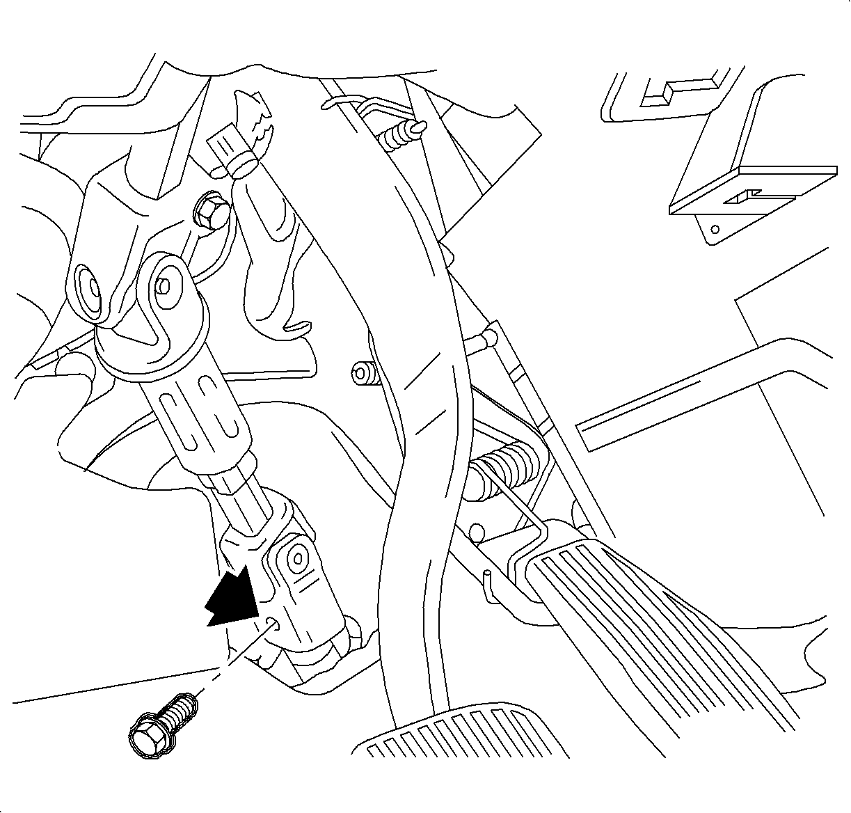
- From inside the vehicle, remove the intermediate shaft to steering gear pinch bolt. Disconnect the shaft from the steering gear.
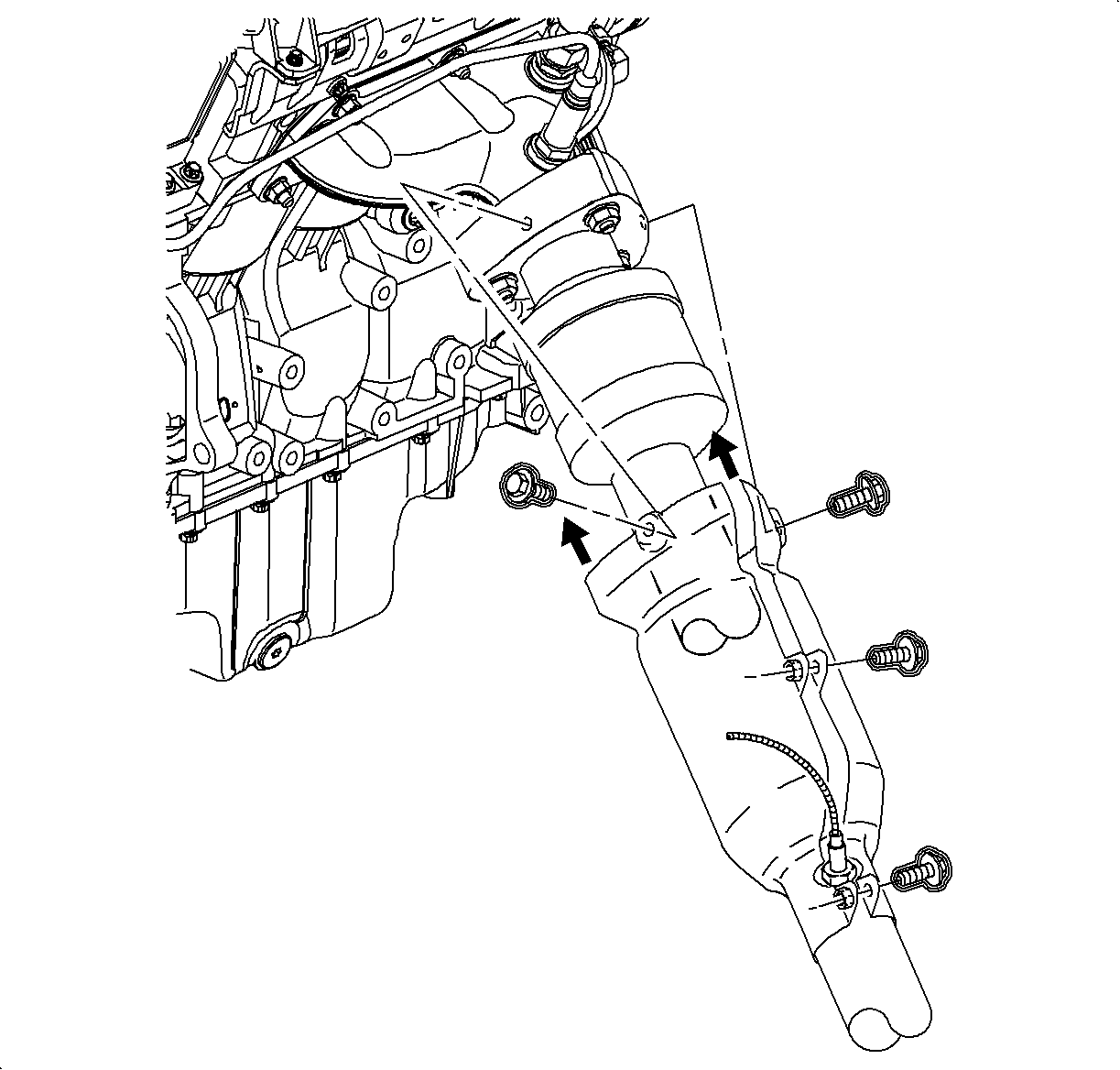
- On vehicles equipped with L81 engines, remove the rear exhaust manifold pipe heat shield.
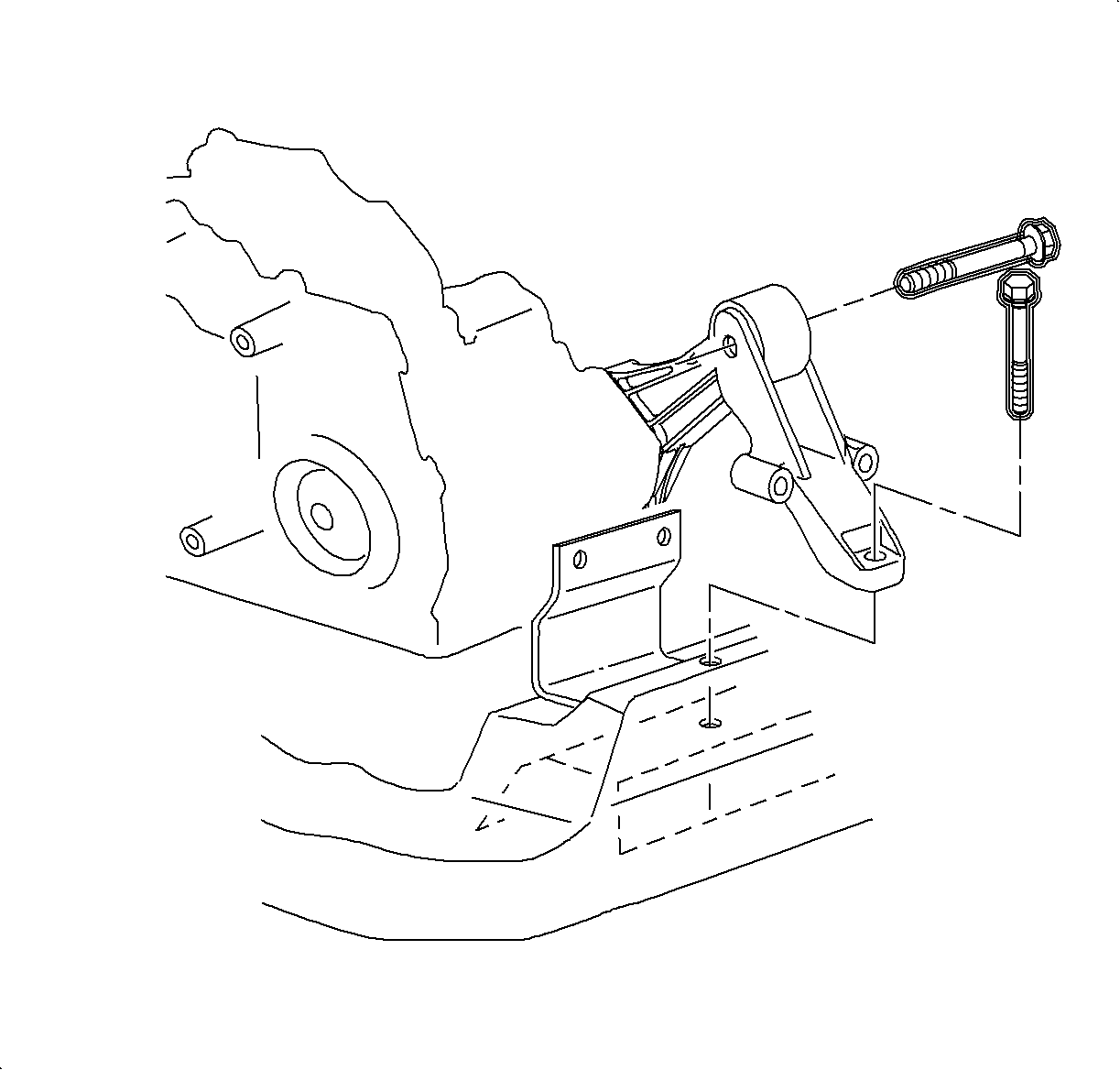
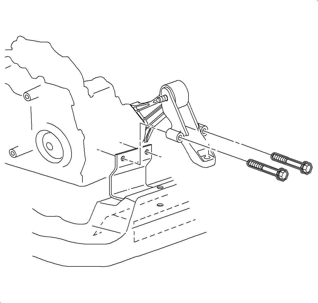
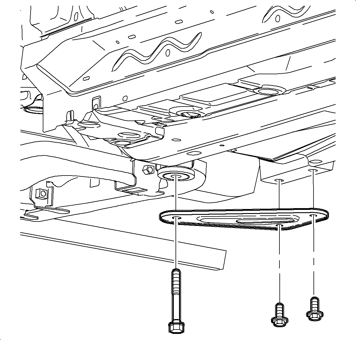
- Remove the rear transaxle mount through bolt, and the transaxle mount-to-frame bolt.
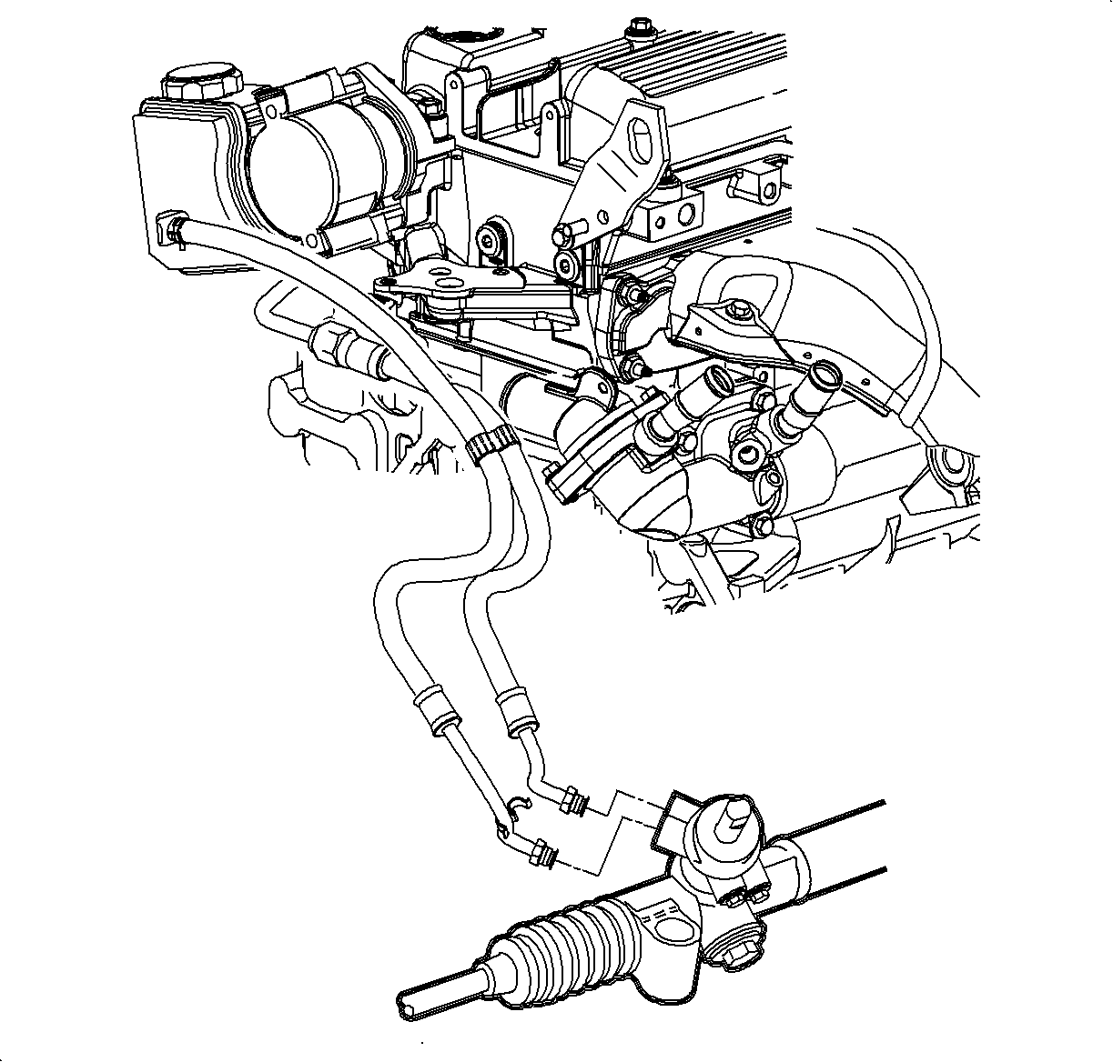
- Place an approved drain container under the pressure and return hoses at the steering gear.
- Remove the power steering pump pressure and return hoses from the steering gear and allow the system to drain.
- Raise the vehicle on a hoist.
- Remove the front wheel and tire assemblies.
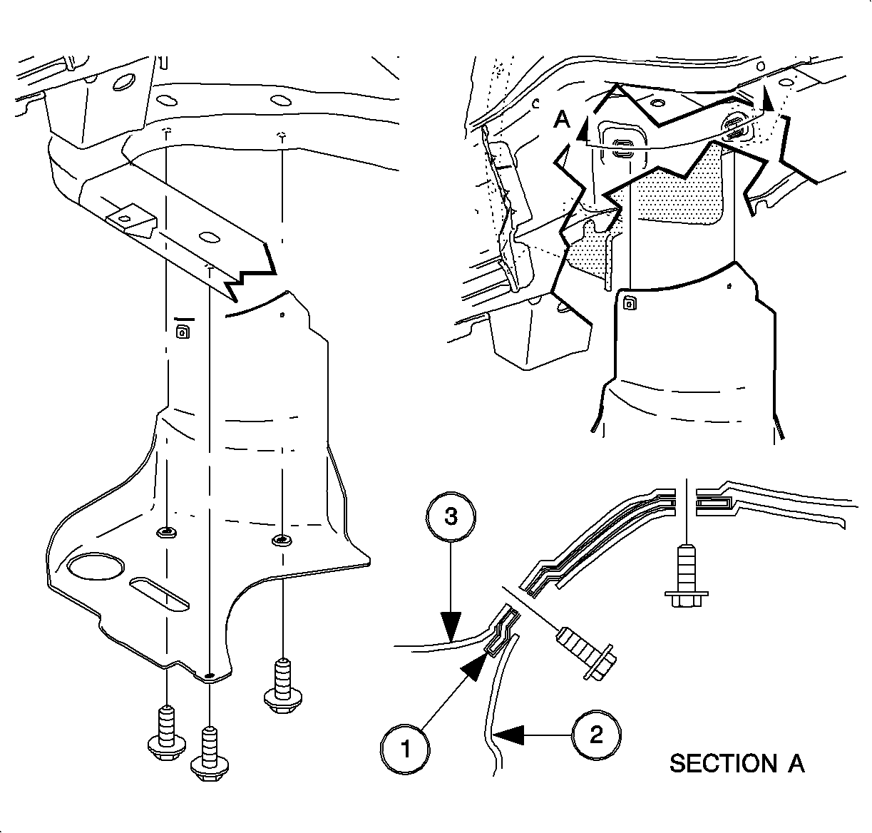
- Remove the right front lower splash shield.
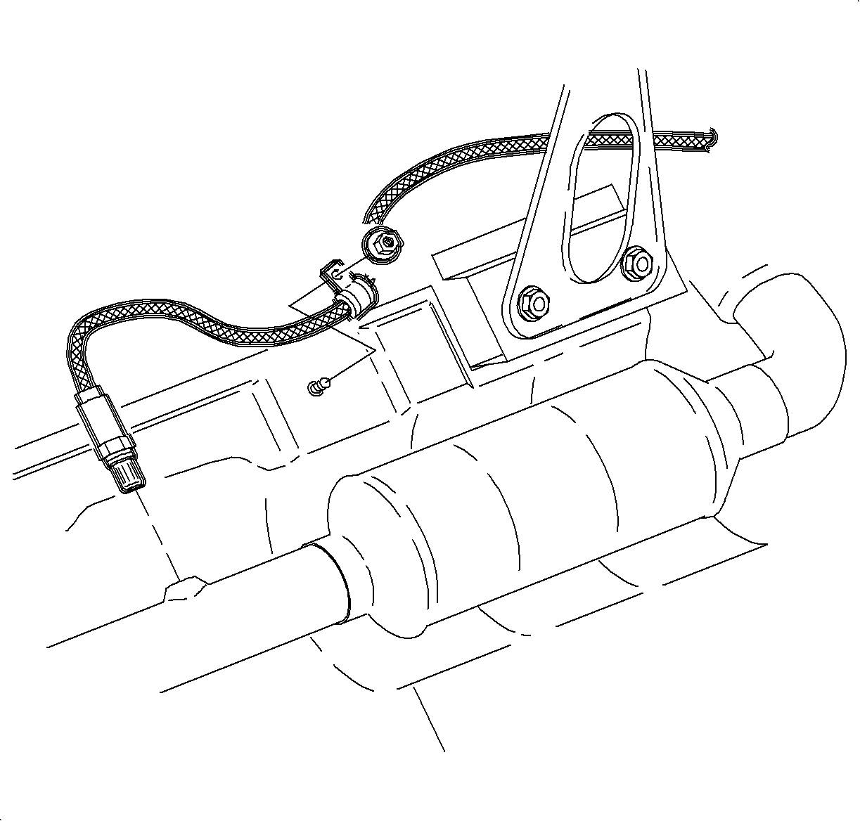
- Disconnect the O2 sensor electrical connection.
- Remove the O2 sensor clamp to underbody attachment nut on a vehicle equipped with L61.
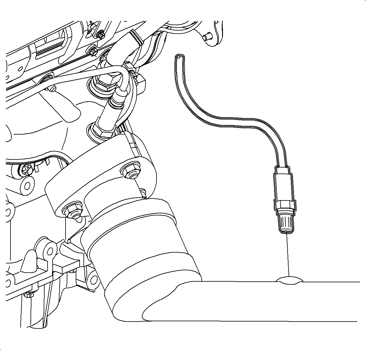
- Remove the O2 sensor from the exhaust manifold pipe on L81 engines.
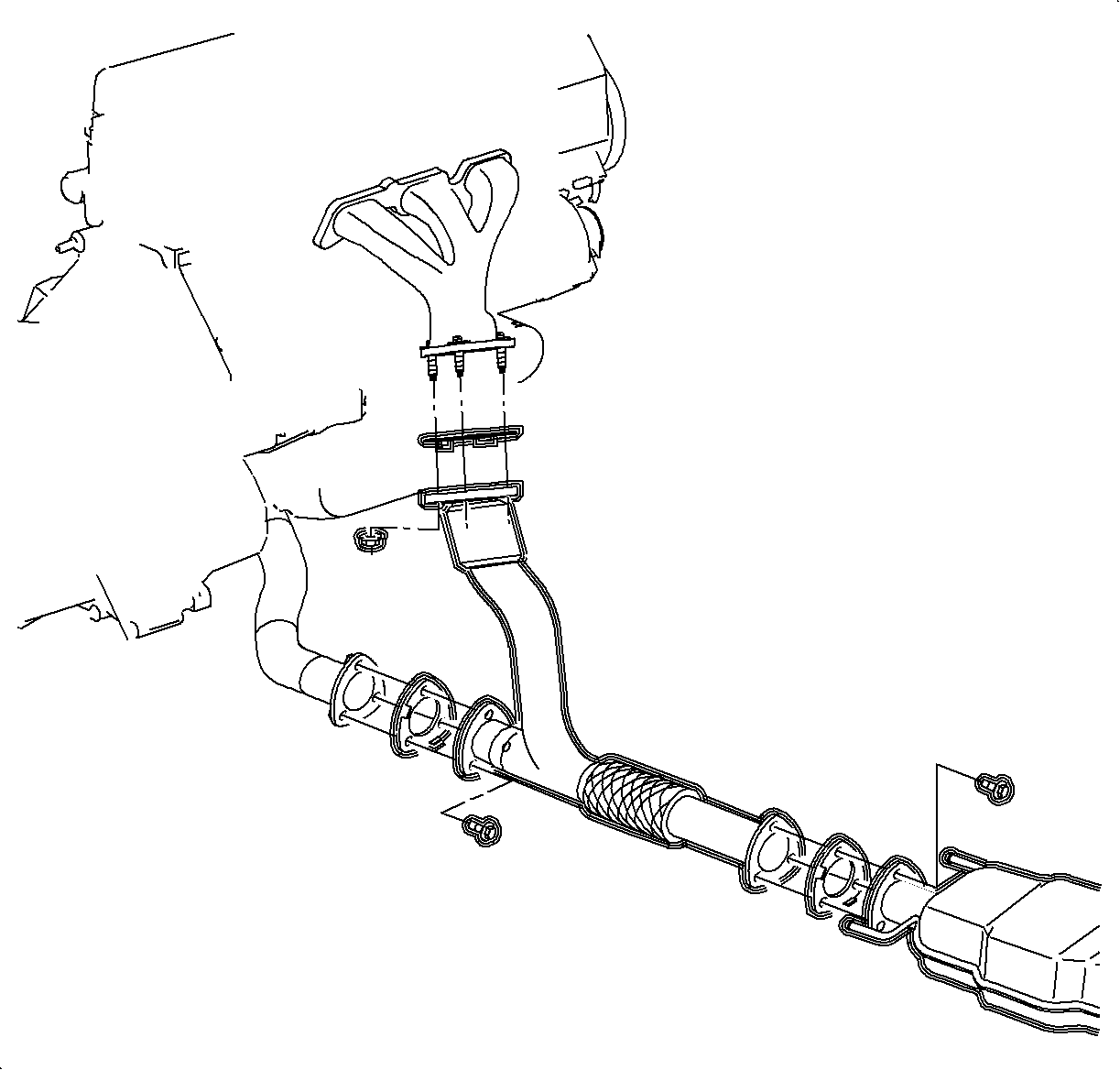
- Remove the exhaust manifold pipe on L81 engines and on L61 engines with manual transmissions. (L81 shown)
- Remove the remaining rear transaxle mount-to-frame bolts.
- Remove the rear transaxle mount.
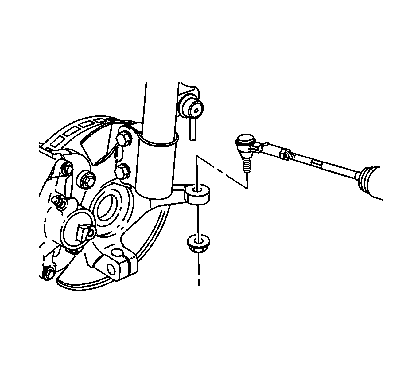
- Remove the tie rod end torque prevailing nuts and discard the nuts.
- Using the , separate the tie rod end from the steering knuckle.
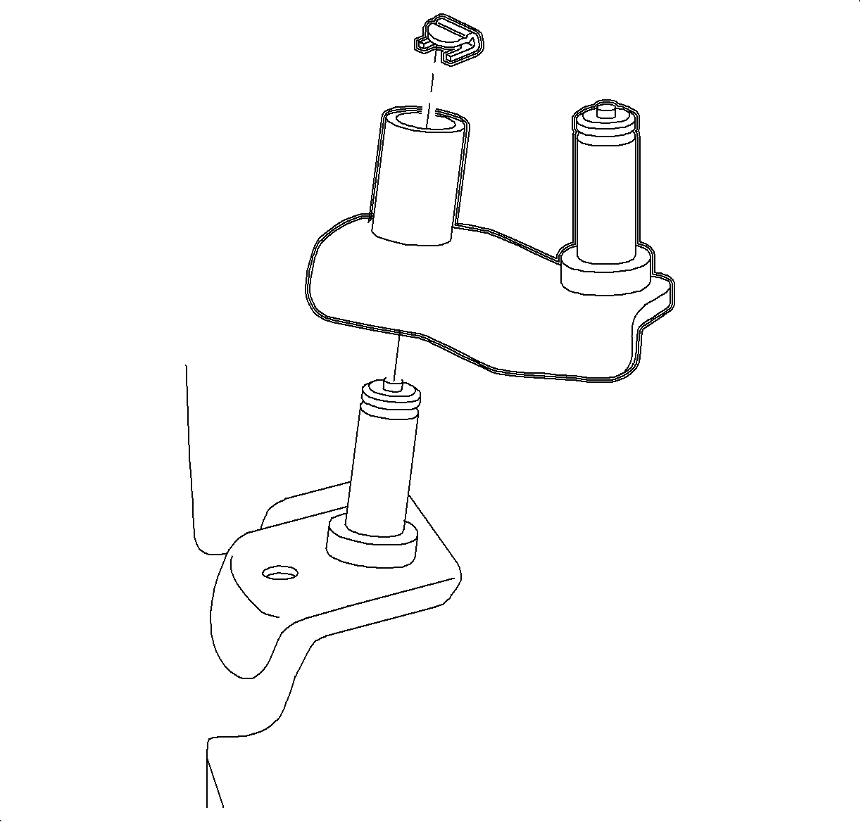
- Remove the cradle to shifter link pivot pin clip on vehicles equipped with an L61 engine and manual transaxle.
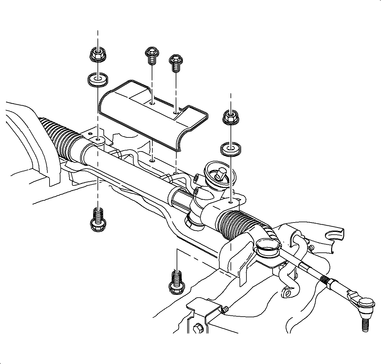
- Remove the steering gear-to-frame assembly bolts.
- On vehicles equipped with an L61 engine and an automatic transaxle, remove the steering gear heat shield.
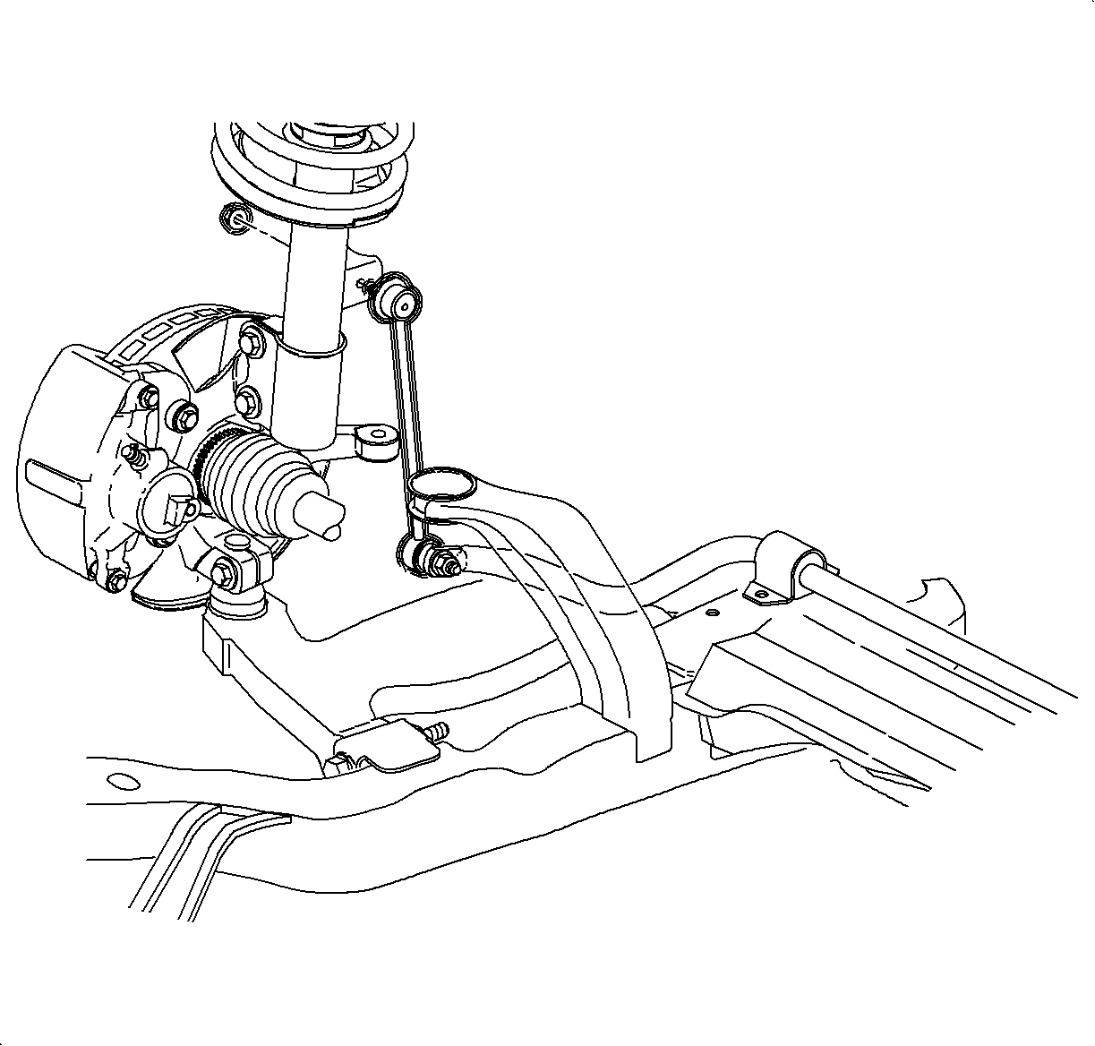
- Remove the stabilizer bar links from the strut assembly.
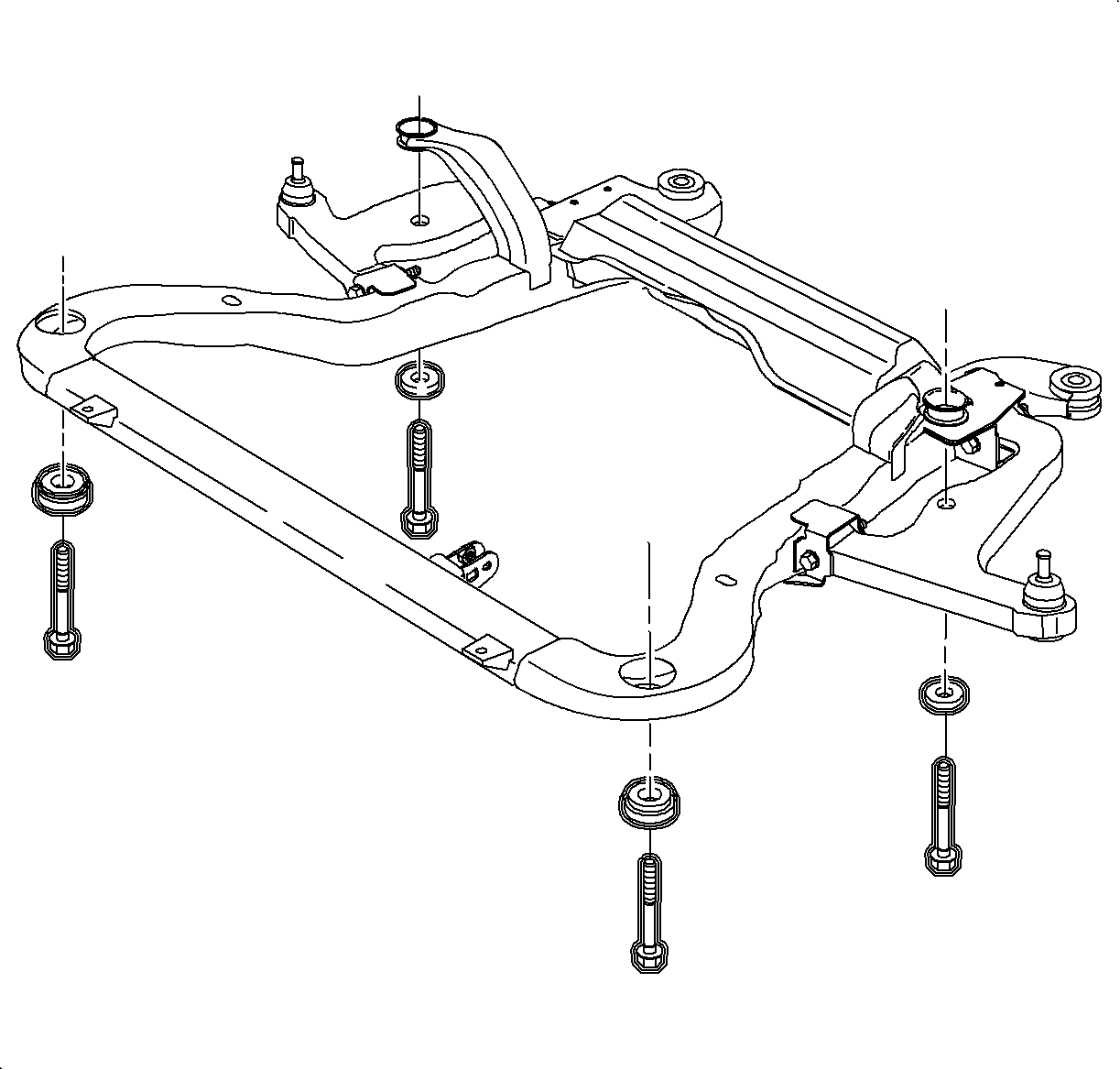
- Remove the front suspension support assemblies.
- Loosen the remaining frame-to-body attachment fasteners until there is enough clearance to remove the steering gear through the drivers side wheel opening.
- Remove the steering gear from vehicle.
Installation Procedure
- One at a time, remove the frame bolts and replace the cage nuts which are located in the body. Use new bolts. The torque retention of old nuts and bolts may not be sufficient.
- Install the steering gear into the vehicle through the left wheel opening.
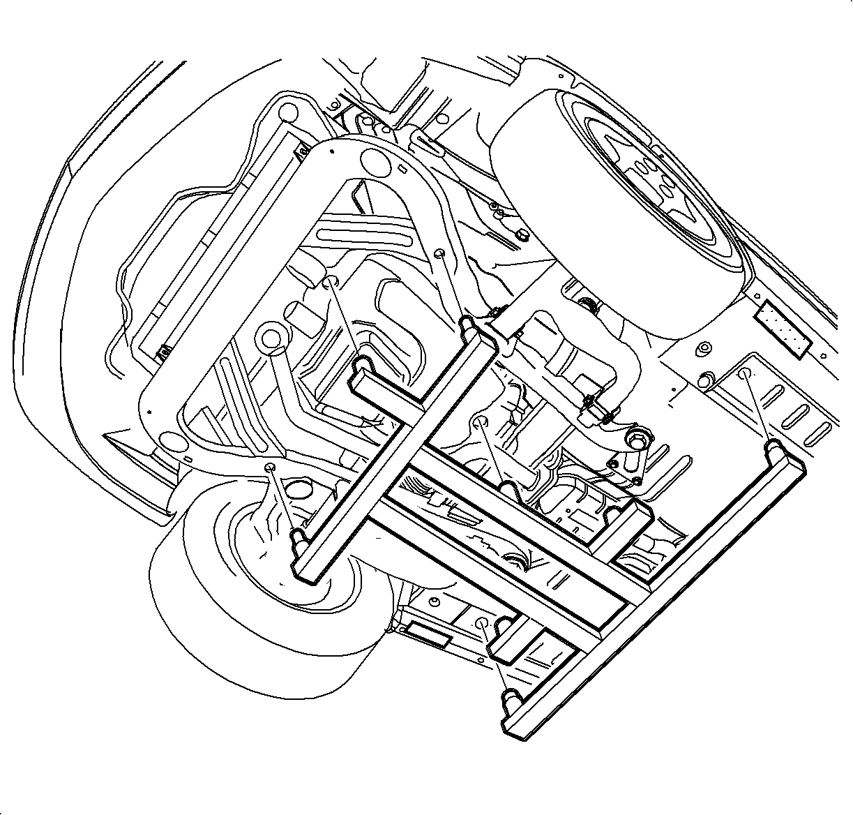
- Using the powertrain support dolly and the J 43628 , raise the frame assembly to the vehicle and tighten the fasteners.
- Install new cage nuts for suspension supports. The torque retention of old nuts may not be sufficient.
- Install the suspension supports using new bolts and tighten.
- On vehicles equipped with L61 and manual transaxle, install the cradle-to-shifter link pivot pin clip.
- Using NEW bolts and nuts, install the steering gear to frame.
- On vehicles equipped with an L61 engine and an automatic transaxle, install the steering gear heat shield.
- Install the tie rod end into the steering knuckle.
- Using the J 44015 , seat the tie rod end into the knuckle.
- Remove the linkage installer and install a NEW tie rod end nut.
- Inspect the boot for damage and replace if damaged.
- Install the stabilizer bar link-to-strut assembly.
- Inspect the boot for damage and replace if damaged.
- Install the rear transaxle mount.
- Install the rear transaxle mount to frame bolts.
- Install the power steering high pressure and return lines.
- Install the exhaust manifold pipe on vehicles equipped with L81 engines, and L61 engines with manual transaxles.
- Tighten the exhaust manifold pipe to exhaust manifold nuts.
- Tighten the exhaust manifold pipe to exhaust pipe bolts.
- Install the O2 sensor clamp to the underbody attachment nut on vehicles equipped with L61.
- Connect the O2 sensor electrical connector.
- Install the wheel and tire assemblies onto the hub.
- Install the wheel bolts and tighten in a crisscross pattern.
- Lower vehicle.
- Install the remaining rear transaxle mount to frame bolt.
- Install the rear transaxle mount through bolt and heat shield, on vehicle with L61 and auto transaxle.
- Install the O2 sensor on exhaust manifold pipe on vehicles equipped with L81 engines.
- Install the exhaust manifold pipe heat shield on vehicles equipped with L81 engines.
- Install the intermediate shaft onto the steering gear and torque pinch bolt.
- Bleed the power steering system. Refer to Power Steering System Bleeding .
- Set the toe. Refer to Front Toe Adjustment in Wheel Alignment.
Tighten
Tighten the frame assembly-to-body bolts to 90 N·m (66 lb ft)
+45-60 degrees.


Tighten
Tighten the suspension support-to-body bolts to 90 N·m (66 lb ft)
+45-60 degrees.


Important: New bolts and nuts must be used as torque retention of old bolts and nuts may not be sufficient.
Tighten
Tighten the steering gear-to-frame to 45 N·m (30 lb ft)
+ 90-105 degrees.
Tighten
Tighten the steering gear heat shield-to-frame to 4 N·m (35 lb in).
Important: The tie rod ends must be thoroughly cleaned before installing and tightening.
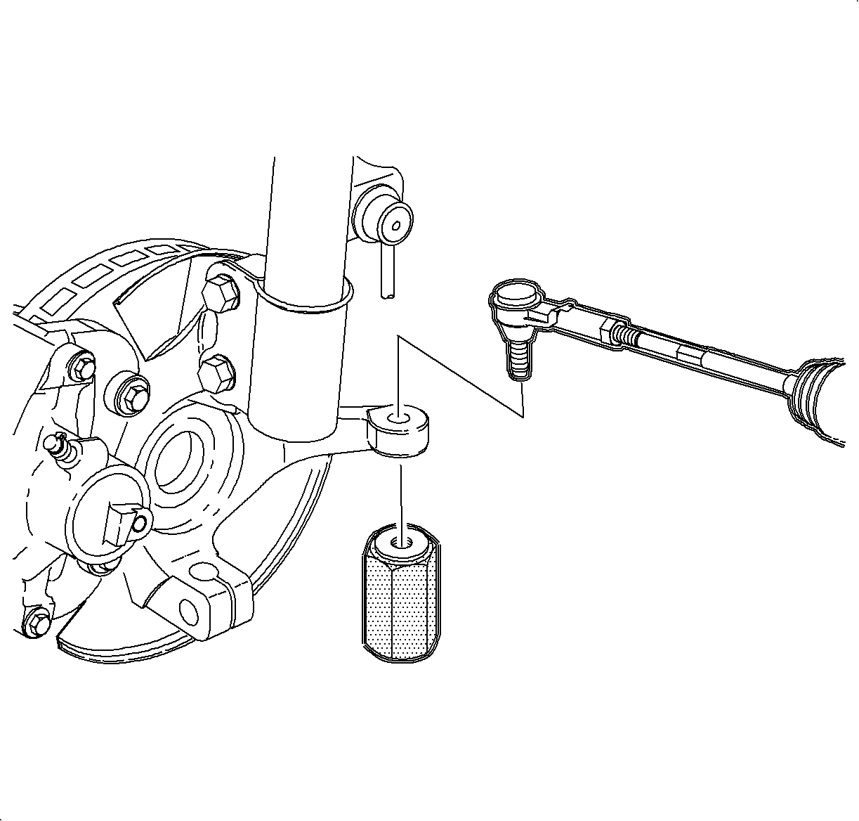
Tighten
Tighten the tie rod end linkage installer to 44 N·m (33 lb ft).
Important: Use a new nut. The torque retention of the old nut may not be sufficient.
Tighten
Tighten the tie rod end-to-steering knuckle nut to 60 N·m (44 lb ft).

Tighten
Tighten the stabilizer bar link-to-strut to 65 N·m (48 lb ft).

Tighten
Tighten the rear transaxle mount-to-frame bolts to 60 N·m (44 lb ft).

Tighten
Tighten the power steering lines-to-steering gear to 27 N·m (20 lb ft).

Tighten
Tighten the exhaust manifold pipe-to-exhaust manifold nuts to 30 N·m
(22 lb ft).
Tighten
Tighten the exhaust manifold pipe-to-exhaust pipe to 20 N·m (15 lb ft).

Tighten
Tighten the O2 sensor clip-to-underbody attachment nut to 4 N·m
(35 lb in).
| • | Hand tighten all 5 wheel bolts. |
| • | Use a torque wrench to tighten the wheel bolts using a crisscross pattern. |
Tighten
Tighten the wheel bolts -- initial torque to 63 N·m (46 lb ft).
| • | Use a torque wrench to final tighten the wheel bolts using a crisscross pattern. |
Tighten
Tighten the wheel bolts -- final torque to 125 N·m (92 lb ft).

Tighten
Tighten the rear transaxle mount-to-frame bolts to 60 N·m (44 lb ft).
Tighten
Tighten the rear transaxle mount through bolts to 90 N·m (66 lb ft).

Tighten
Tighten the O2 sensor on exhaust manifold pipe (L81) to 45 N·m
(33 lb ft).

Tighten
Tighten the exhaust manifold pipe heat shield bolts to 8 N·m (71 lb in).

Important: Use Loctite® Threadlocker, or equivalent on threads of pinch bolt.
Tighten
Tighten the intermediate shaft pinch bolt to 30 N·m (22 lb ft).
