For 1990-2009 cars only
Tools Required
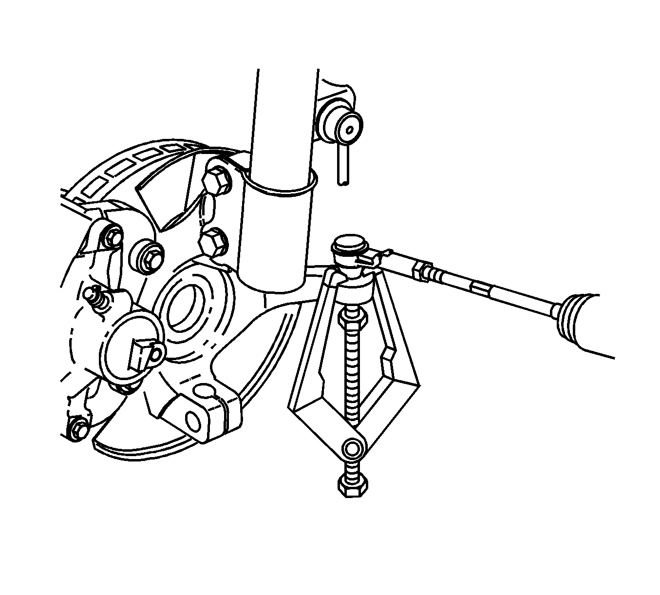
| • | SA91100C Tie Rod Separator |
| • | J 44015 Steering Linkage Installer |
Removal Procedure
- Raise and support the vehicle. Refer to Lifting and Jacking the Vehicle in General Information.
- Remove the tire and wheel. Refer to Tire and Wheel Removal and Installation in Tires and Wheels.
- Remove the brake rotor. Refer to Front Brake Rotor Replacement in Disc Brakes.
- Remove the dust shield screws.
- If equipped with ABS, remove the ABS sensor bracket bolt from the steering knuckle.
- Carefully remove the ABS sensor bracket assembly from the steering knuckle.
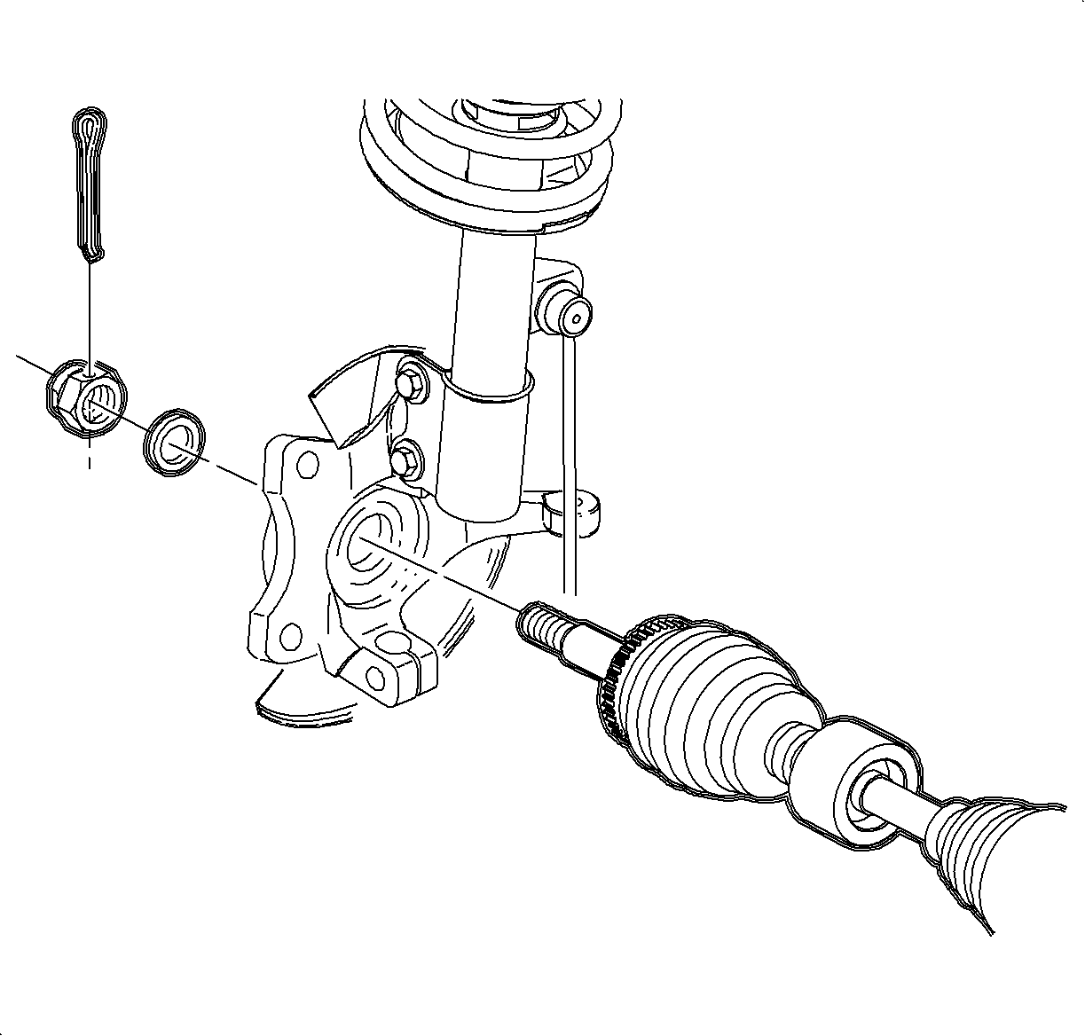
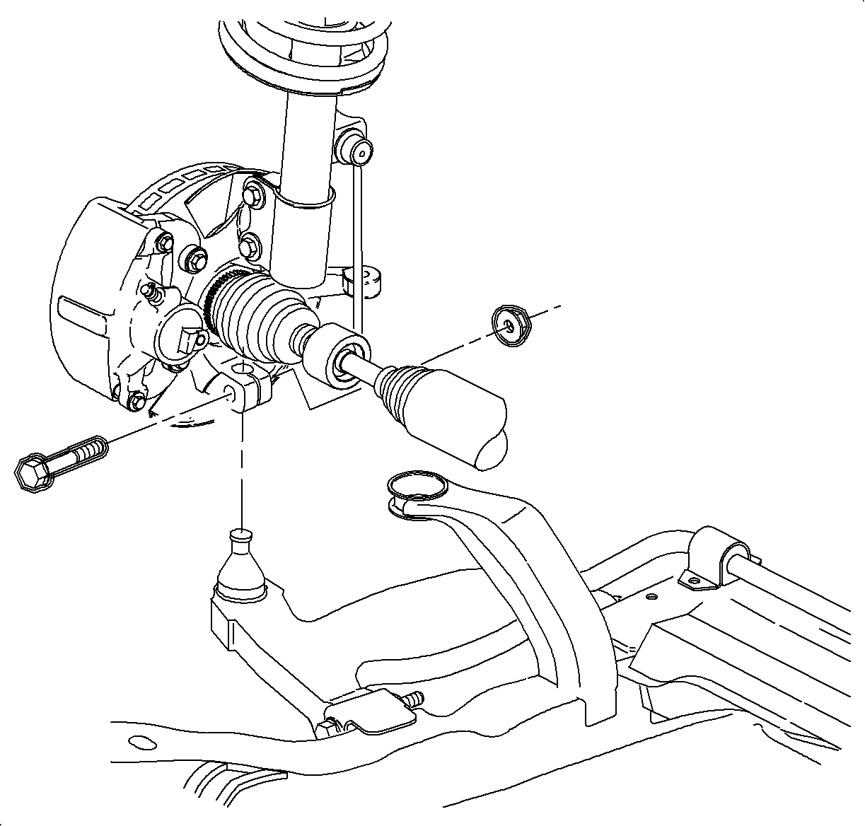
- Remove the drive axle to hub nut. Discard the nut.
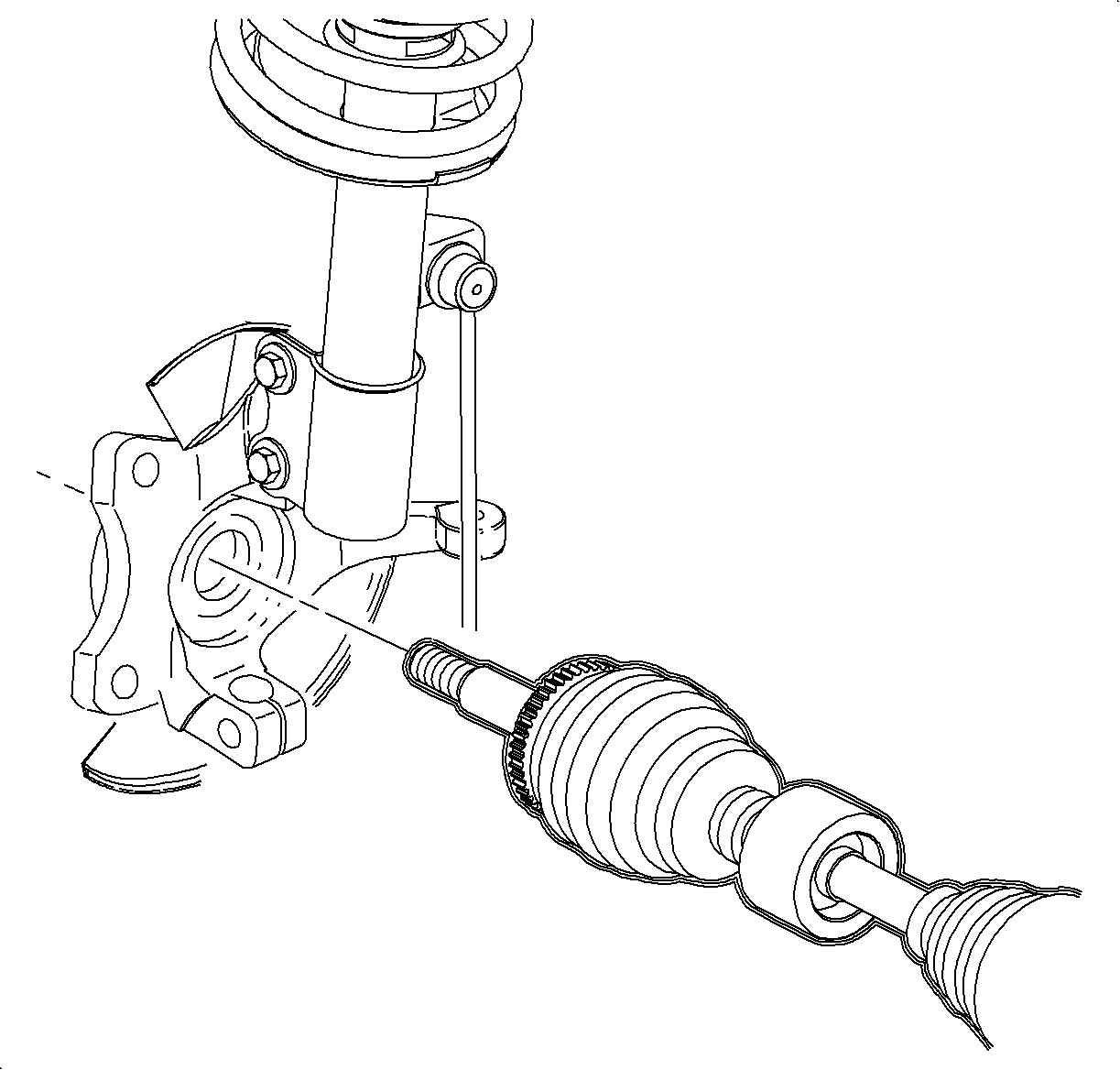
- Disengage the drive axle from the steering knuckle.
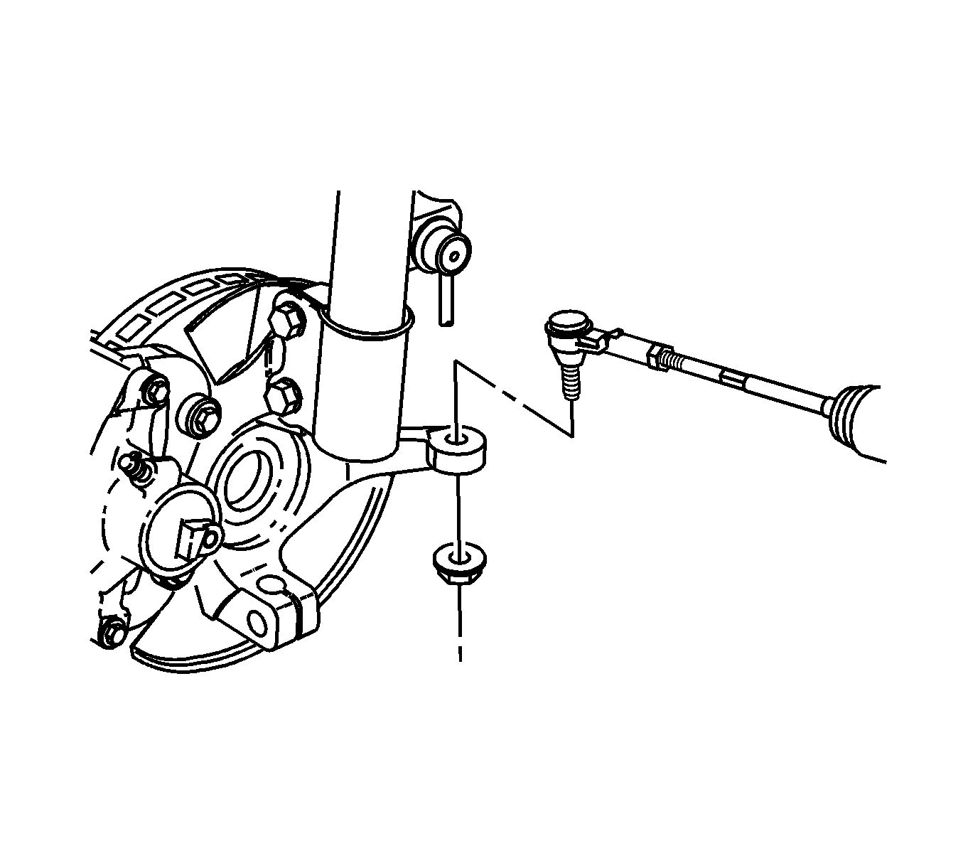
- Remove the outer tie rod to knuckle nut.
- Using the SA91100C , separate the tie rod from the steering knuckle.
- Remove the lower control arm ball stud to steering knuckle pinch bolt and nut.
- Lower the control arm to separate the ball stud from the steering knuckle.
- Support and protect the drive axle during steering knuckle removal.
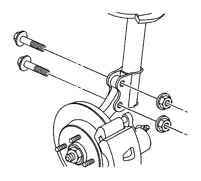
- Remove the strut to steering knuckle bolts and nuts.
- Remove the steering knuckle from the vehicle.
- Remove the hub/bearing from the steering knuckle. Refer to Front Wheel Bearing and Hub Replacement .
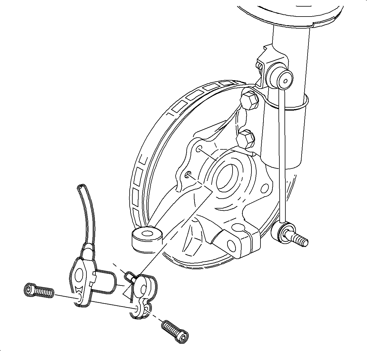
Important: The ABS sensor bracket is equipped with a locating pin. Do not break this pin.
Installation Procedure
- Install the hub/bearing to the steering knuckle. Refer to Front Wheel Bearing and Hub Replacement .
- Position the steering knuckle on the lower control arm ball stud, while guiding the drive axle through the steering knuckle hub/bearing.
- Install new strut to knuckle nuts and bolts. Snug the bolts only at this time.
- Install the lower control arm ball stud to steering knuckle pinch bolt and nut.
- Using the J 44015 , install the tie rod to the steering knuckle. Set the taper by tightening the J 44015 to 45 N·m (33 lb ft).
- Remove the J 44015 and install a new tie rod to steering knuckle nut.
- Inspect the tie rod boot for damage, replace if necessary.
- If equipped with ABS, install the ABS sensor assembly to the steering knuckle.
- Install the brake rotor and hydraulic brake caliper. Refer to Front Brake Rotor Replacement in Disc Brakes.
- Install the washer and a new hub/bearing nut to the drive axle.
- Tighten the nut to 115 N·m (85 lb ft).
- Back of the nut and tighten to 20 N·m (15 lb ft) plus an additional 90 degrees.
- Install a new cotter pin through the alignment hole in the drive axle. Rotate the drive axle nut clockwise as necessary to align the castle nut slots.
- Install the tire and wheels. Refer to Tire and Wheel Removal and Installation in Tires and Wheels.
- Lower the vehicle.
- Align the front end. Refer to Wheel Alignment Measurement in Wheel Alignment.

Notice: Refer to Fastener Notice in the Preface section.

Tighten
Tighten the bolt and nut to 100 N·m
(74 lb ft).
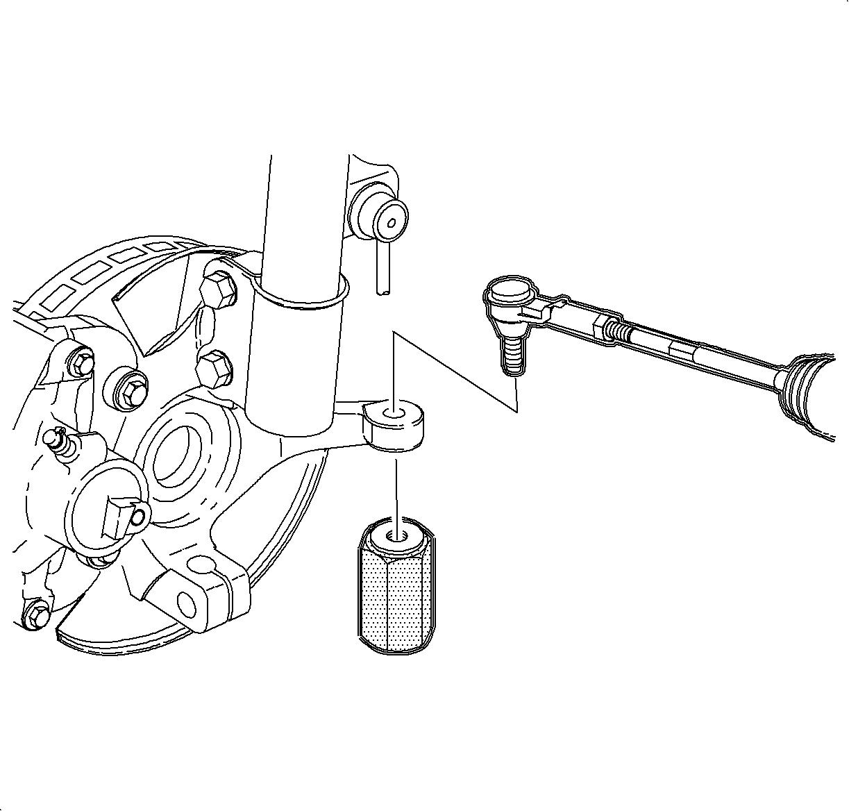

Important: Do not allow the ball stud to turn when installing the tie rod to steering knuckle nut.
Tighten
Tighten the nut to 60 N·m (45 lb ft).

Important: The ABS sensor bracket has a locating pin. The pin must be lactated in the steering knuckle locating hole.
Tighten
Tighten the ABS sensor bracket bolt to 8 N·m
(71 lb in).

Tighten
