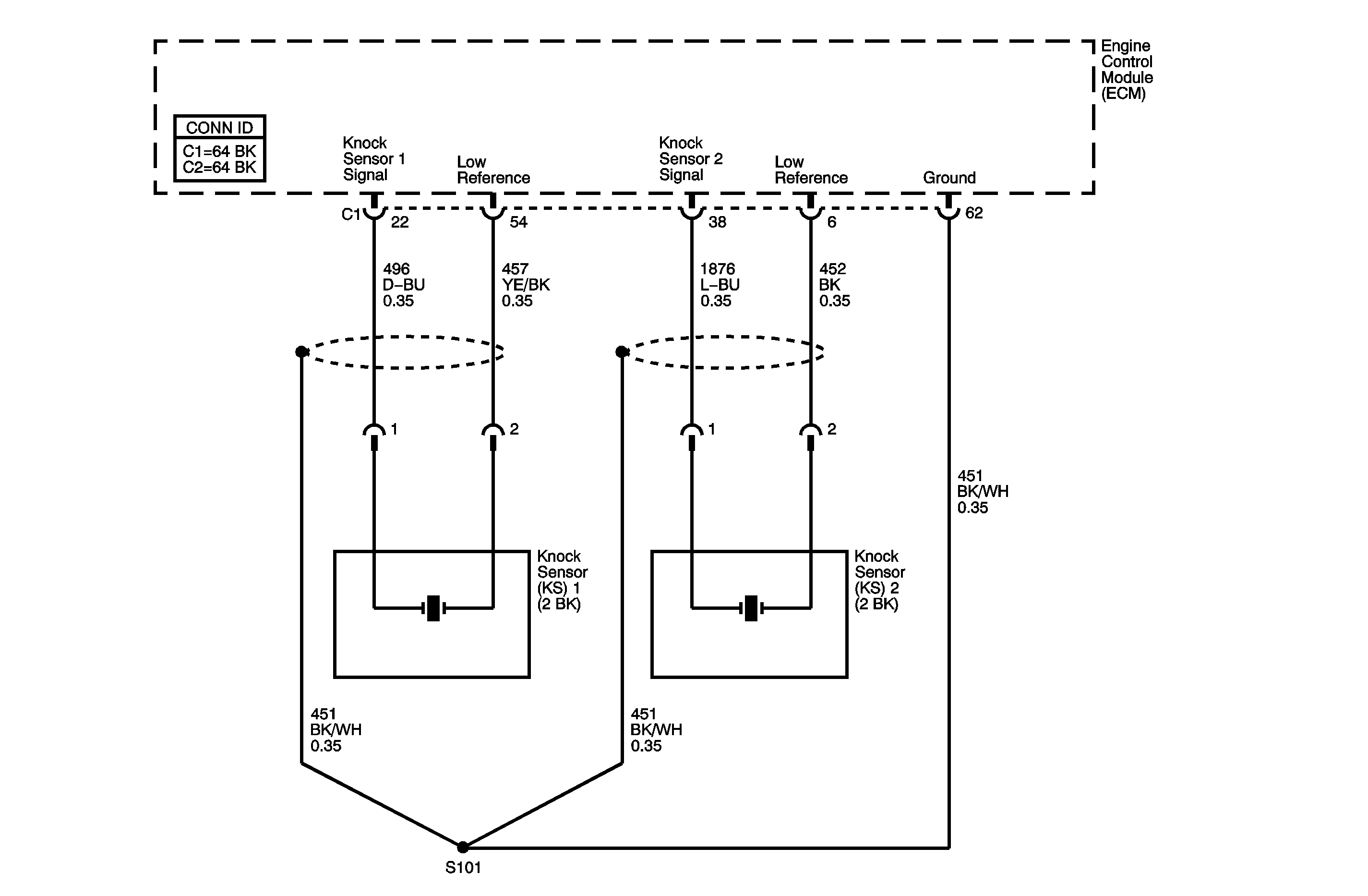
Circuit Description
The knock sensor (KS) system enables the engine control module (ECM) to control the ignition timing for the best possible performance while protecting the engine from potentially damaging levels of detonation. The KS system uses two sensors.
KS 1 is located on the right side of the engine, or the rear of the engine compartment.
KS 2 is located on the left side of the engine, or the front of the engine compartment.
The KS produces an AC voltage signal that varies depending on the vibration level during engine operation. The ECM adjusts the spark timing based on the amplitude and the frequency of the KS signal. The ECM receives the KS signal through a signal circuit. The KS ground is supplied by the ECM through a low reference circuit. The ECM learns the minimum and the maximum amplitude of the noise that the engine produces. The ECM should monitor a normal KS signal within the voltage range. If the ECM detects the KS signal outside of the voltage range, or the KS signal is not present, a DTC sets. DTC P0327 refers to KS 1 and DTC P0332 refers to KS 2.
DTC Descriptors
This diagnostic procedure supports the following DTCs:
| • | DTC P0327 Knock Sensor (KS) Circuit Low Voltage Bank 1 |
| • | DTC P0332 Knock Sensor (KS) Circuit Low Voltage Bank 2 |
Conditions for Running the DTC
| • | The engine coolant temperature (ECT) sensor is more than 40°C (104°F). |
| • | The engine speed is more than 2,000 RPM. |
| • | The engine load is more than 40 percent. |
| • | DTC P0327 and P0332 run continuously once the above conditions are met. |
Conditions for Setting the DTC
The KS signal is below the normal operating range or the KS signal is not present for more than 300 seconds.
Action Taken When the DTC Sets
| • | The control module illuminates the malfunction indicator lamp (MIL) on the second consecutive ignition cycle that the diagnostic runs and fails. |
| • | The control module records the operating conditions at the time the diagnostic fails. The first time the diagnostic fails, the control module stores this information in the Failure Records. If the diagnostic reports a failure on the second consecutive ignition cycle, the control module records the operating conditions at the time of the failure. The control module writes the operating conditions to the Freeze Frame and updates the Failure Records. |
Conditions for Clearing the MIL/DTC
| • | The control module turns OFF the malfunction indicator lamp (MIL) after 3 consecutive ignition cycles that the diagnostic runs and does not fail. |
| • | A current DTC, Last Test Failed, clears when the diagnostic runs and passes. |
| • | A history DTC clears after 40 consecutive warm-up cycles, if no failures are reported by this or any other emission related diagnostic. |
| • | Clear the MIL and the DTC with a scan tool. |
Diagnostic Aids
| • | Inspect the KS for physical damage. A KS that is dropped or damaged may cause a DTC to set. |
| • | Inspect the KS for proper installation. A KS that is loose or over torqued may cause a DTC to set. The KS should be free of thread sealant. The KS mounting surface should be free of burrs, casting flash, and foreign material. |
| • | The KS must be clear of hoses, brackets, and engine electrical wiring. |
| • | For an intermittent condition, refer to Intermittent Conditions . |
Step | Action | Yes | No | ||||||||
|---|---|---|---|---|---|---|---|---|---|---|---|
Schematic Reference: Engine Controls Schematics Connector End View Reference: Engine Control Module Connector End Views or Engine Controls Connector End Views | |||||||||||
1 | Did you perform the Diagnostic System Check - Vehicle? | Go to Step 2 | Go to Diagnostic System Check - Vehicle in Vehicle DTC Information | ||||||||
2 |
Did the DTC fail this ignition? | Go to Step 3 | Go to Diagnostic Aids | ||||||||
3 |
Does the DMM display OL for both terminals? | Go to Step 4 | Go to Step 9 | ||||||||
4 |
Important: DO NOT tap on plastic engine components. Does the DMM display a fluctuating frequency while tapping on the engine block? | Go to Step 5 | Go to Step 9 | ||||||||
5 |
Refer to Circuit Testing and Wiring Repairs in Wiring Systems. Did you find and correct the condition? | Go to Step 11 | Go to Step 6 | ||||||||
6 | Test the KS low reference circuit between the ECM and the KS for the following conditions:
Refer to Circuit Testing and Wiring Repairs in Wiring Systems. Did you find and correct the condition? | Go to Step 11 | Go to Step 7 | ||||||||
7 | Test for an intermittent and for a poor connection at the KS connector. Refer to Testing for Intermittent Conditions and Poor Connections and Connector Repairs in Wiring Systems. Did you find and correct the condition? | Go to Step 11 | Go to Step 8 | ||||||||
8 | Test for an intermittent and for a poor connection at the ECM. Refer to Testing for Intermittent Conditions and Poor Connections and Connector Repairs in Wiring Systems. Did you find and correct the condition? | Go to Step 11 | Go to Step 10 | ||||||||
9 | Replace the KS. Refer to Knock Sensor 1 Replacement or Knock Sensor 2 Replacement . Did you complete the replacement? | Go to Step 11 | -- | ||||||||
10 | Replace the ECM. Refer to Control Module References in Computer/Integrating Systems for replacement, setup, and programming. Did you complete the replacement? | Go to Step 11 | -- | ||||||||
11 |
Did the DTC fail this ignition? | Go to Step 2 | Go to Step 12 | ||||||||
12 | Observe the Capture Info with a scan tool. Are there any DTCs that have not been diagnosed? | Go to Diagnostic Trouble Code (DTC) List - Vehicle in Vehicle DTC Information | System OK | ||||||||
