For 1990-2009 cars only
Tools Required
| • | J 39400-A Halogen Leak Detector |
| • | J 43600 ACR 2000 Air Conditioning Service Center |
Removal Procedure
- Disconnect the negative battery cable. Refer to Battery Negative Cable Disconnection and Connection in Engine Electrical.
- Recover the refrigerant. Refer to Refrigerant Recovery and Recharging .
- Drain the coolant. Refer to Cooling System Draining and Filling in Engine Cooling.
- Remove the following heater inlet hoses:
- Remove the following heater outlet hoses:
- Place the end of the heater return hose in a container. Apply a low pressure 34 kPa (5 psi) of shop air to the heater inlet hose to blow the coolant out of the heater core.
- Install the heater return hose to the nipple and position the clamp:
- Install the heater inlet hose as follows and position the clamps at the 12 o'clock position:
- Remove the heater inlet hose from the heater core pipe.
- Remove the heater outlet hose from the heater core pipe.
- Remove the nut that secures the evaporator hose assembly to the TXV .
- Remove the evaporator hose assembly from the TXV.
- Remove the I/P assembly. Refer to Instrument Panel Assembly Replacement in Instrument Panel, Gages and Console.
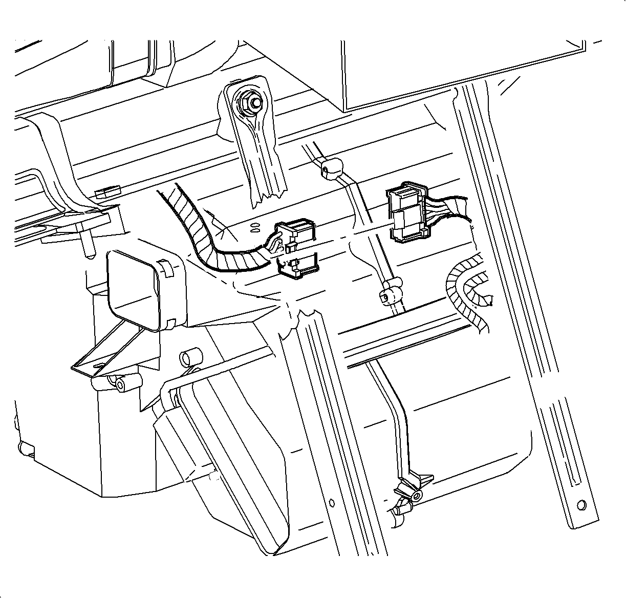
- Disconnect the I/P harness electrical connector from the module harness.
- Remove the wiper arm assemblies. Refer to Windshield Wiper Arm Replacement in Washer/Wiper Systems.
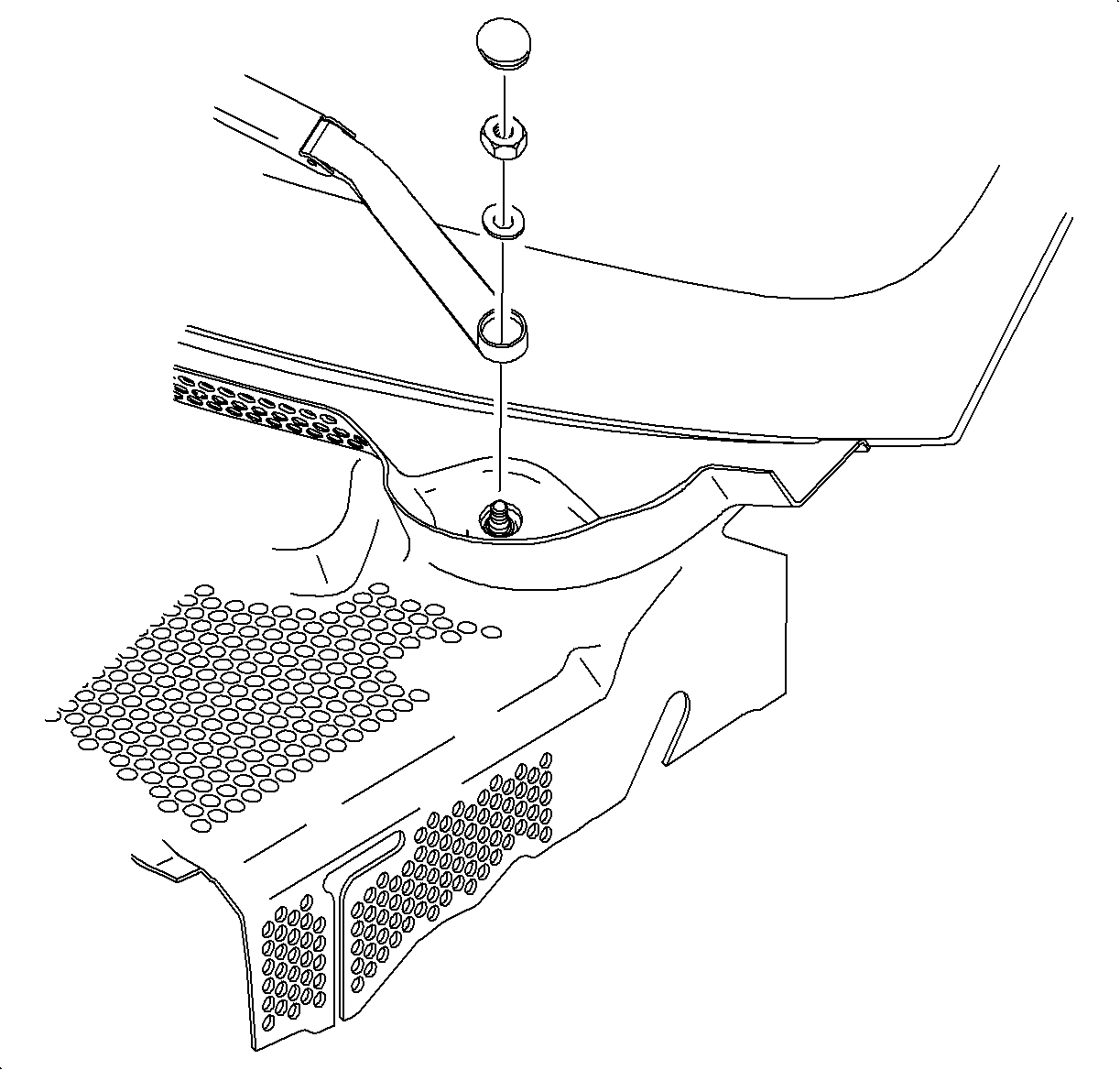
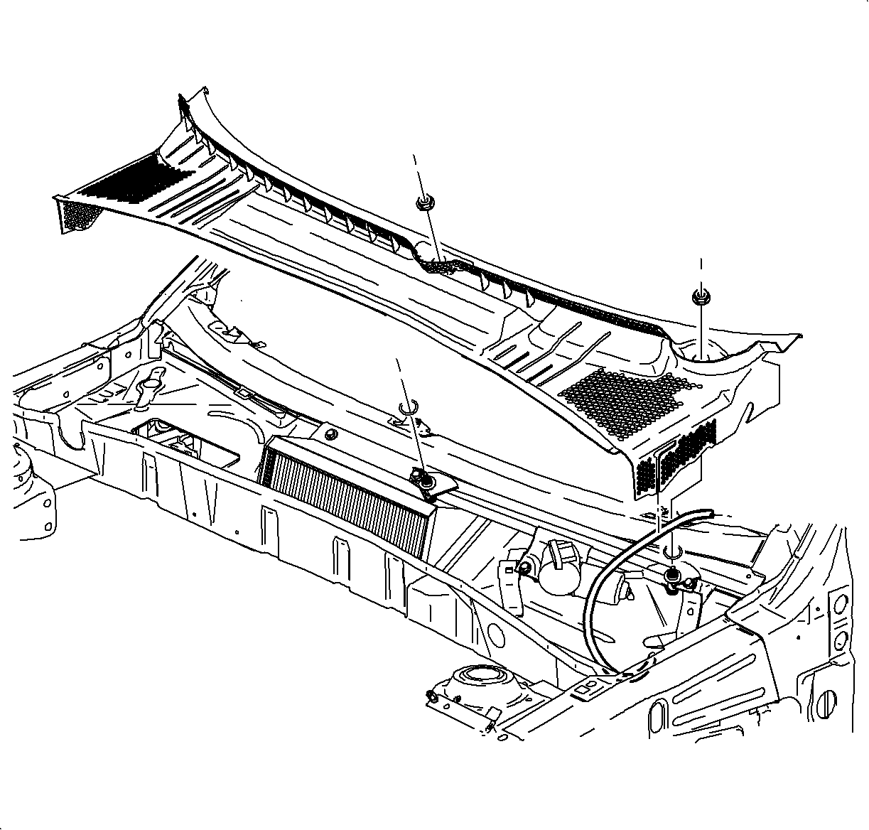
- Remove the cowl retaining nuts and remove the cowl screen assembly.
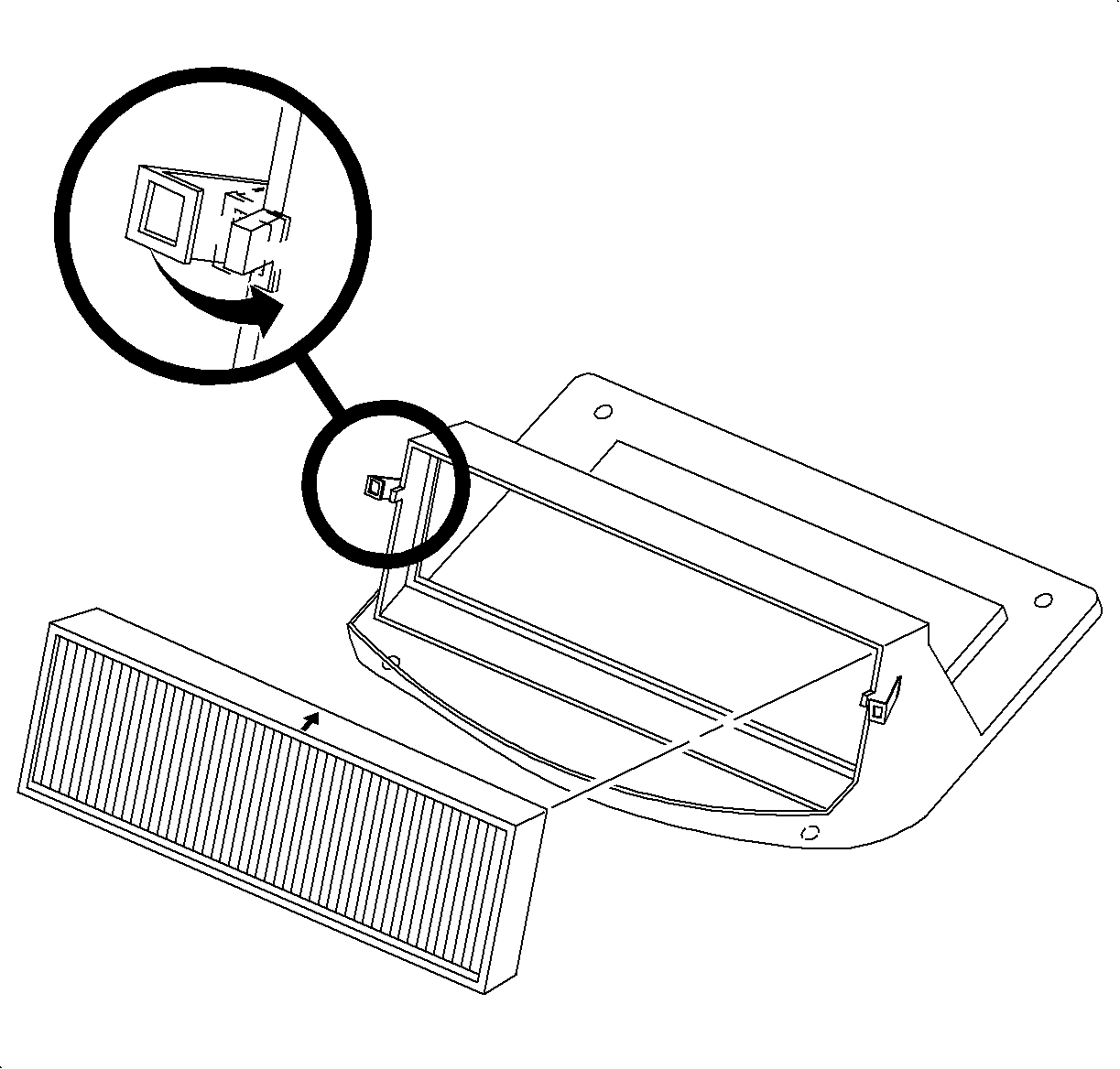
- Rotate the locking tabs outward to release the filter assembly.
- Remove the filter by lifting straight up.
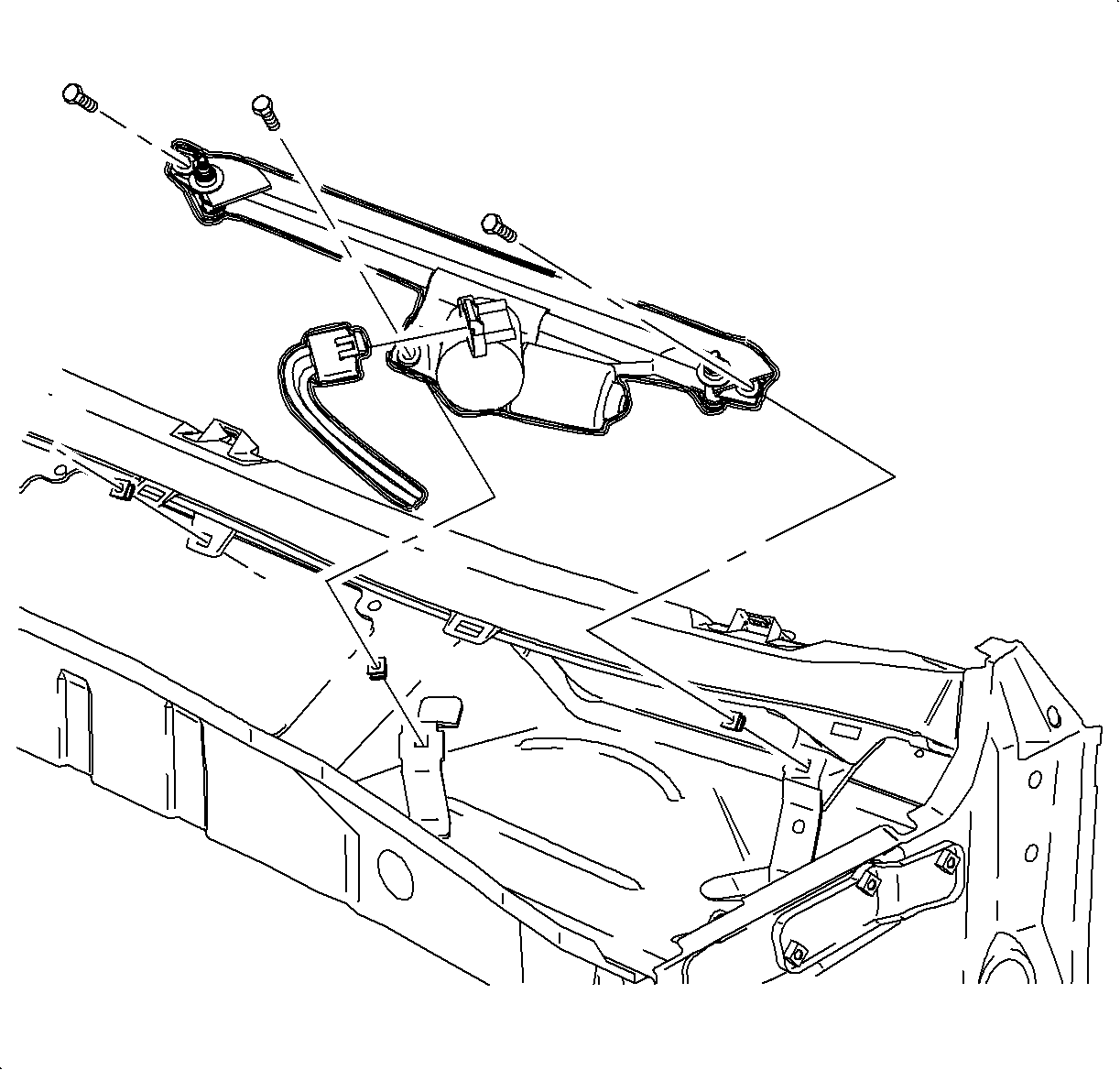
- Remove the wiper module retaining bolts and slide the wiper module to the right.
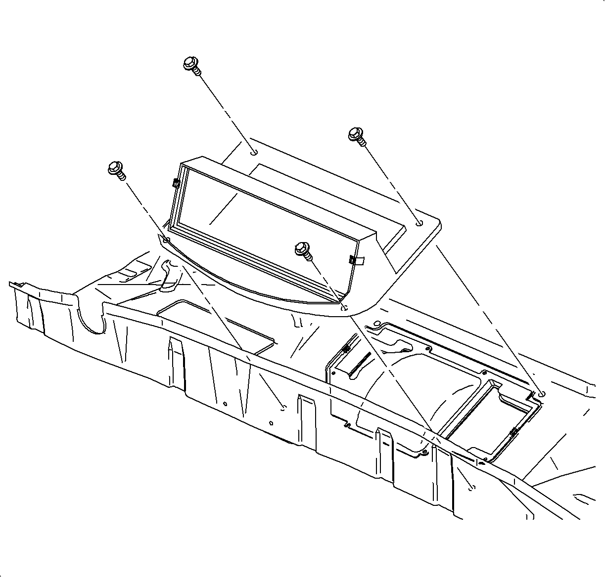
- Remove the filter housing attachment bolts and remove the filter housing.
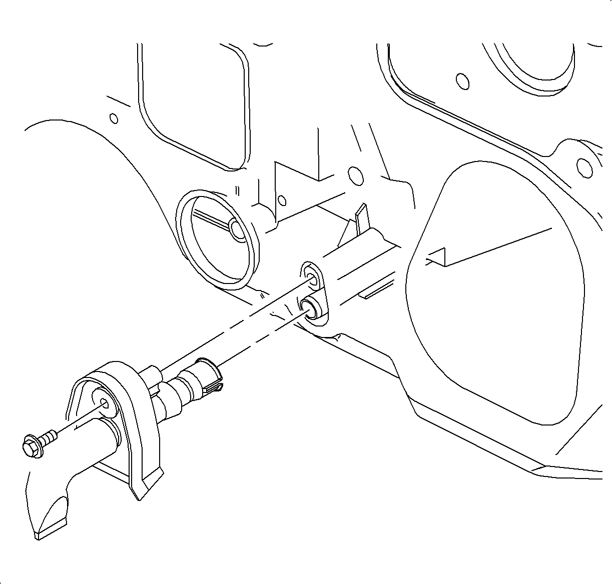
- Remove the evaporator drain tube bolt.
- Remove the evaporator drain tube.
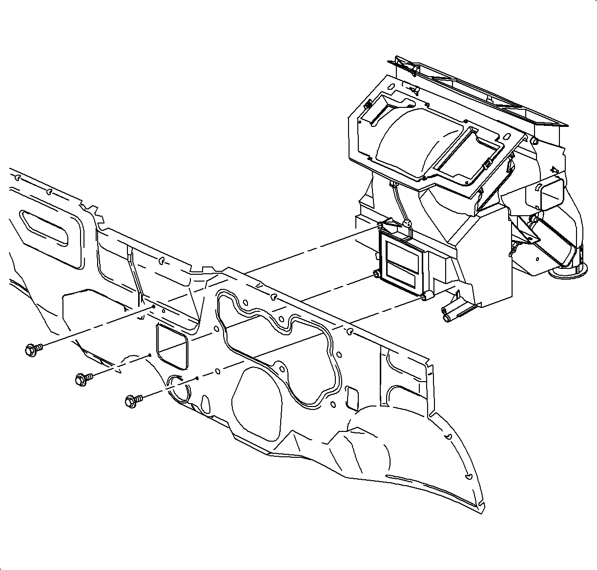
- Remove the bolts that secure the HVAC module to the front of the dash.
- Remove the HVAC module from the vehicle.
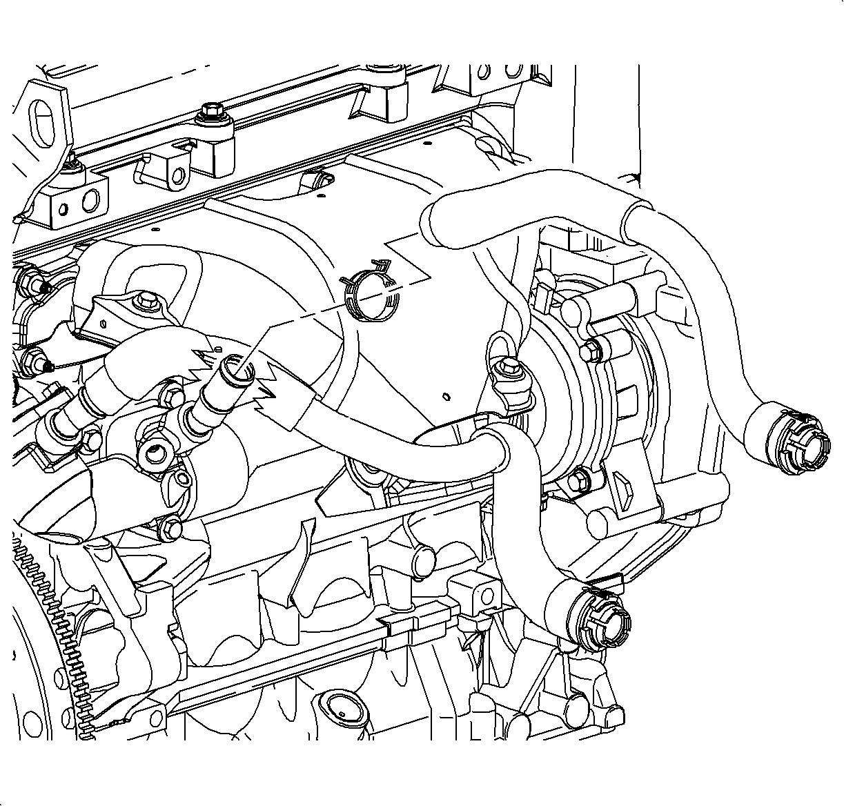
| • | From the auxiliary water pump outlet on L81 engines |
| • | From the thermostat outlet on L61 engines |
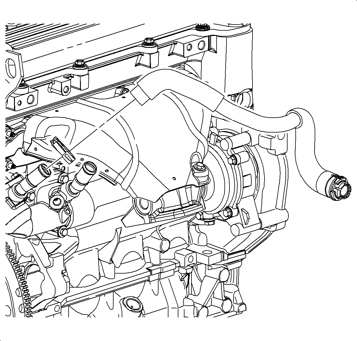
| • | From the cylinder head bridge on L81 engines |
| • | From the block inlet on L61 engines |
| • | At the 6 o'clock position on the L81 |
| • | At the 12 o'clock position on the L61 |
| • | To the auxiliary water pump outlet on the L81 |
| • | At the thermostat outlet on the L61 |
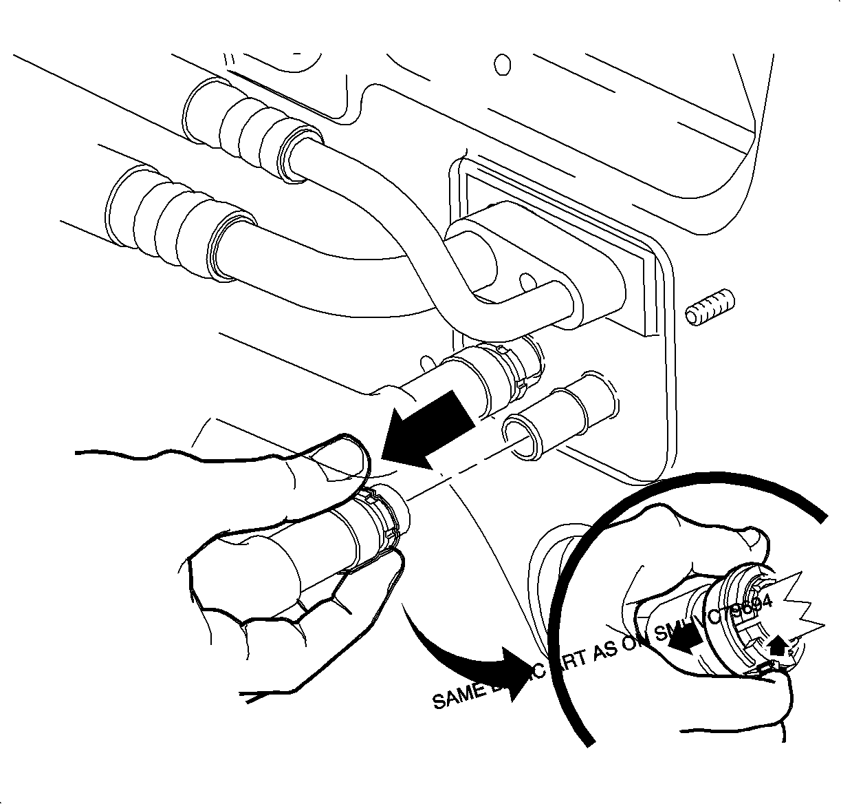
Important: Green plastic rings may be found hanging on the pipes after hose removal, these are manufacturing aids and should be discarded.
| 9.1. | Depress the quick connect collar tab located at the 6 o'clock position . |
| 9.2. | Pull the black collar toward the front of vehicle. |
| 9.3. | Pull the quick connect off the heater core pipe. |
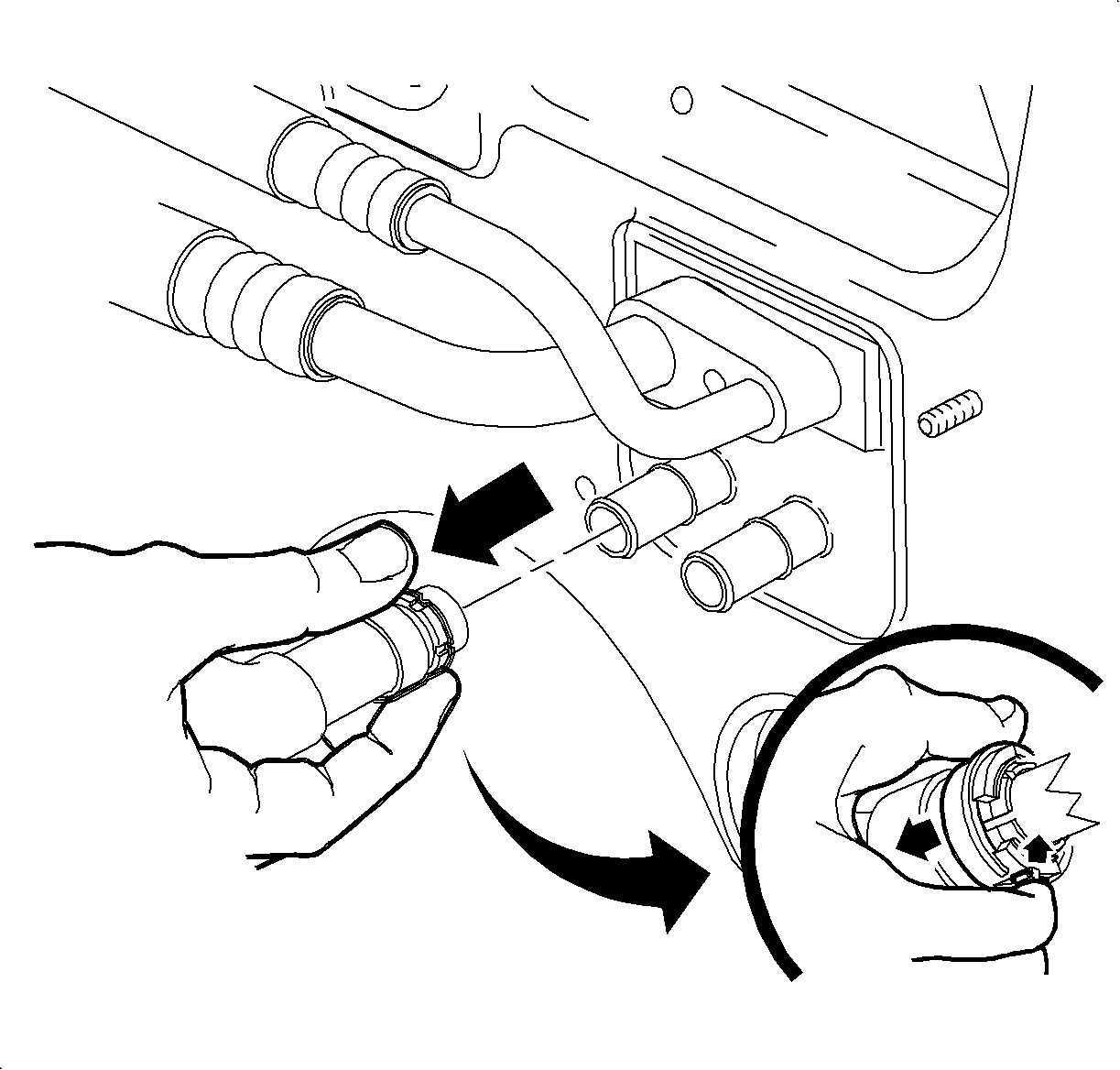
| 10.1. | Depress the quick connect collar tab located at the 6 o'clock position. |
| 10.2. | Pull the black collar toward the front of vehicle. |
| 10.3. | Pull the quick connect off the heater core pipe. |
Installation Procedure
- Install the module into the vehicle.
- Install the HVAC module to the front of the dash, and hand start the bolts.
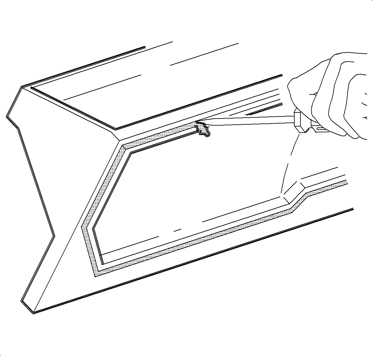
- Remove the filter housing seal using a small flat-bladed tool.
- Install a new filter housing seal.
- Install the filter housing and screws.
- Position the wiper module and install the bolts.
- Tighten the bolts that secure the HVAC module to the front of the dash.
- Install the evaporator drain tube and install the bolt.
- Install the passenger compartment air filter paying special attention to the air flow direction indicator.
- Rotate the locking tabs to secure the air filter in place.
- Install the cowl screen and the nuts.
- Close the filter access door.
- Install the wiper arm assemblies. Refer to Windshield Wiper Arm Replacement in Washer/Wiper Systems.
- Install the heater inlet hose.
- Install the heater outlet hose.
- Install the I/P assembly. Refer to Instrument Panel Assembly Replacement in Instrument Panel, Gages and Console.
- Remove the protective cap from the TXV.
- Thoroughly clean the O-ring surfaces of the TXV.
- Remove the caps.
- Install new O-rings. Refer to O-Ring Replacement .
- Install the evaporator hose assembly block to the TXV and install the nut.
- Fill the cooling system. Refer to Cooling System Draining and Filling in Engine Cooling.
- Evacuate and recharge the A/C system. Refer to Refrigerant Recovery and Recharging .
- Using J 39400-A , leak test the fittings of the component.

Notice: Refer to Fastener Notice in the Preface section.

Tighten
Tighten the screws to 3.5 N·m (31 lb in).

Tighten
Tighten the bolts to 5 N·m (44 lb in).

Tighten
Tighten the bolts to 4.5 N·m (40 lb in).
Tighten
Tighten the bolt to 3.5 N·m (31 lb in).


Tighten
Tighten the nuts to 1.0 N·m (9 lb in).

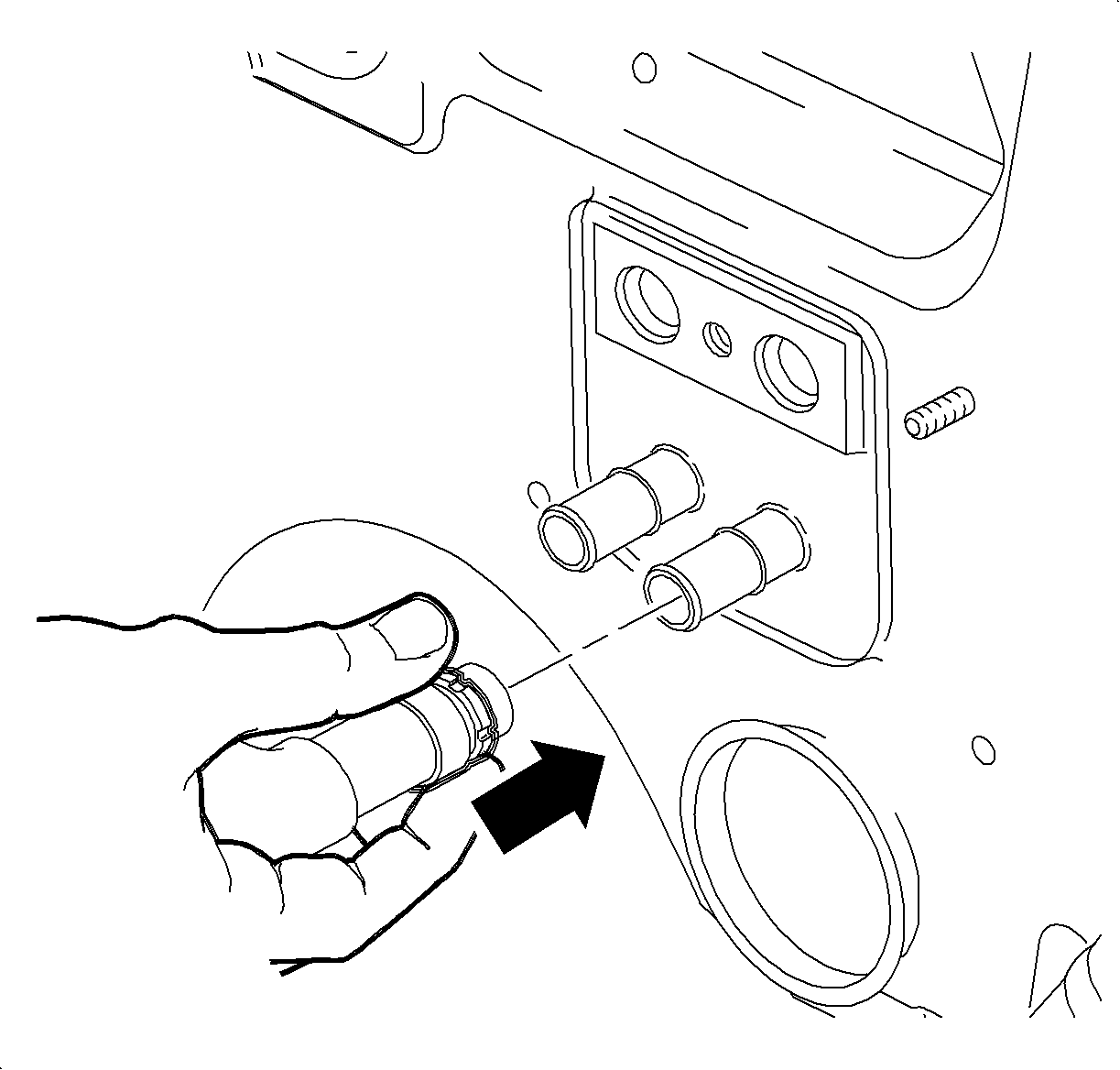
| 14.1. | Hold the hose by black quick connect collar and slide the hose onto the heater core pipe until the quick connect collar engages over the bead on the heater core pipe. |
| 14.2. | Ensure that a green band is visible in the quick connect collar. |
| 14.3. | Pull on the hose to ensure it is properly seated. |
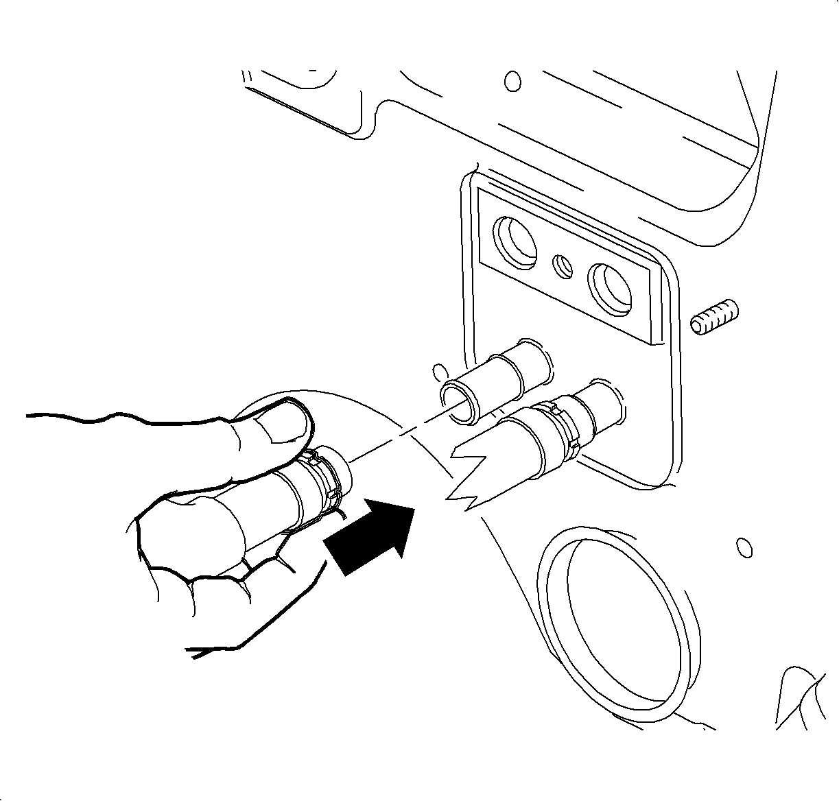
| 15.1. | Install the heater outlet hose, closest to passenger side. |
| 15.2. | Ensure that a green band is visible in the quick connect collar. |
| 15.3. | Pull on the hose to ensure the hose is properly seated. |
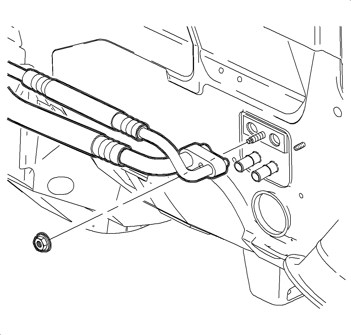
Tighten
Tighten the nut to 7 N·m (62 lb in).
