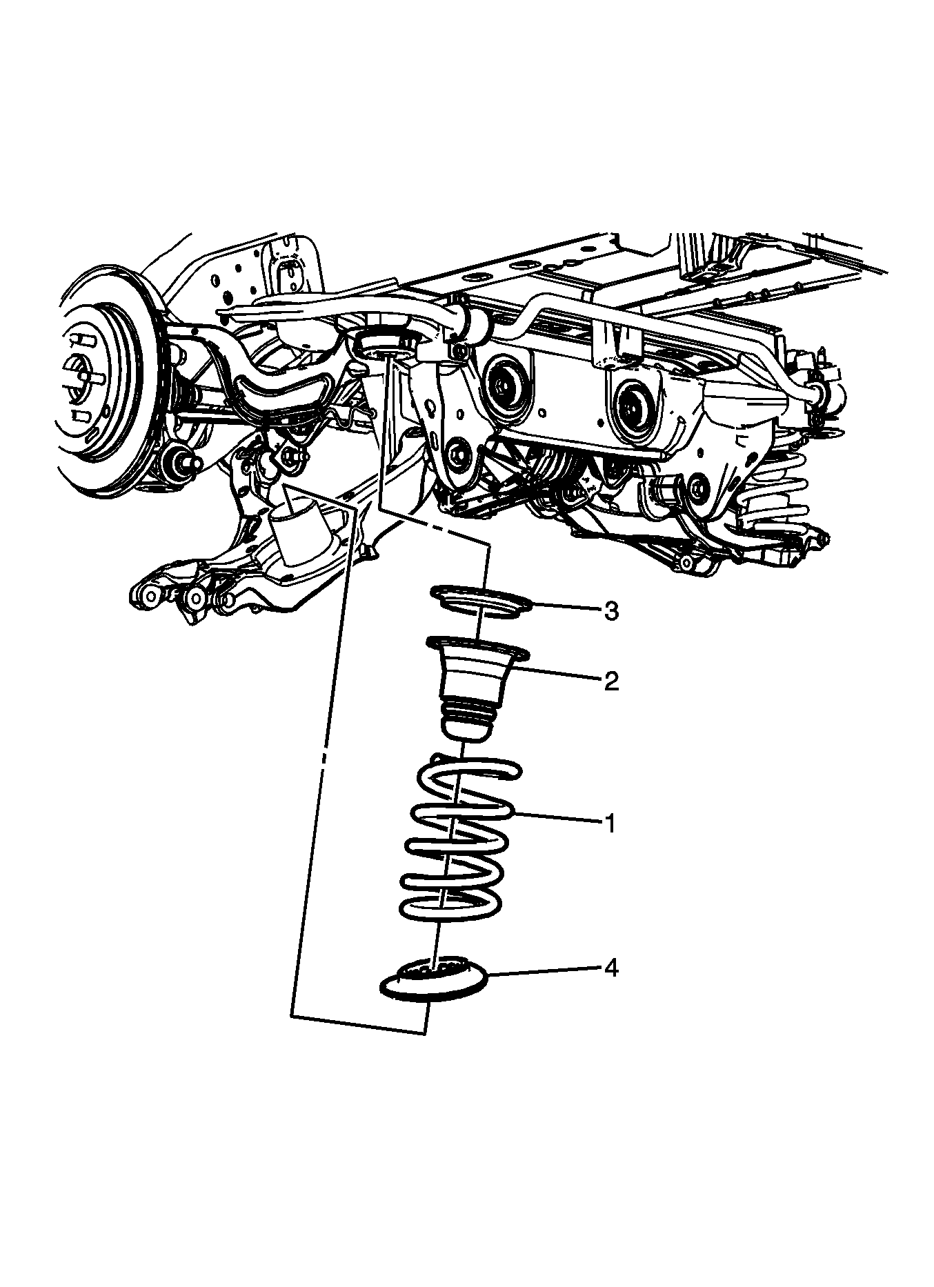
For 1990-2009 cars only
Removal Procedure
- Raise and support the vehicle. Refer to Lifting and Jacking the Vehicle .
- Remove the rear tire and wheel. Refer to Tire and Wheel Removal and Installation .
- Position an adjustable jack stand under the lower control arm .
- Remove the lower stabilizer shaft link bushing and nut. Refer to Stabilizer Shaft Link Replacement .
- Remove the lower shock absorber bolt. Refer to Shock Absorber Replacement .
- Remove the lower bolts from the knuckle. Refer to Knuckle Replacement .
- Using the adjustable jack stand, slowly lower the vehicle until the rear spring (1), insulator (4), jounce bumper (2), and the spring seat (3) can be removed.

Installation Procedure
- Position the spring seat (3), jounce bumper (2), rear spring (1), and the insulator (4) on the lower control arm.
- Using the adjustable jack stand, raise the lower control arm until the lower bolts for the knuckle can be installed. Refer to Knuckle Replacement .
- Remove the adjustable jack stand.
- Install the lower stabilizer shaft link bushing and nut. Refer to Stabilizer Shaft Link Replacement .
- Install the lower shock absorber bolt. Refer to Shock Absorber Replacement .
- Install the rear tire and wheels. Refer to Tire and Wheel Removal and Installation .
- Remove the support and lower the vehicle.

