Removal Procedure
- Disconnect the negative battery cable. Refer to Battery Negative Cable Disconnection and Connection in Engine Electrical.
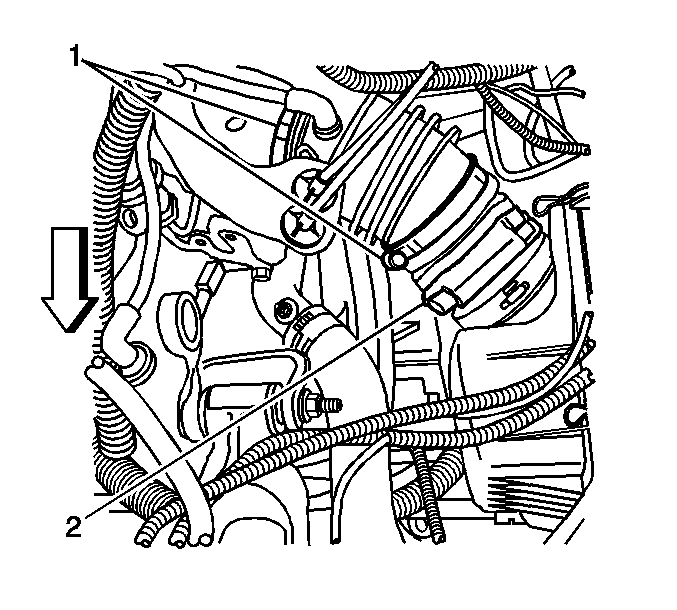
- Loosen the 2 intake air duct clamps (1) from air cleaner housing (2) and the throttle body.
- Remove the air cleaner intake duct from the air cleaner housing and throttle body.
- Drain the cooling system. Refer to Cooling System Draining and Filling in Engine Cooling.
- Remove the radiator inlet hose from the engine. Refer to Radiator Inlet Hose Replacement in Engine Cooling.
- Remove the radiator outlet hose from the engine. Refer to Radiator Outlet Hose Replacement in Engine Cooling.
- Remove the heater outlet and inlet hoses from the engine. Refer to Heater Inlet Hose/Pipe and Heater Outlet Hose/Pipe Replacement in Heating Ventilation and Air Conditioning.
- Remove the vacuum hoses from the upper intake manifold.
- Remove the brake booster vacuum hose from the upper intake manifold.
- Remove the fuel lines from the fuel rail. Refer to Fuel Injection Fuel Rail Assembly Replacement in Engine Controls - 3.5L.
- Disconnect the following electrical connectors:
- Remove the engine wiring harness grounds from the transaxle.
- Remove the engine mount strut. Refer to Engine Mount Strut Replacement - Left Side and Engine Mount Strut Replacement - Right Side .
- Raise and support the vehicle. Refer to Lifting and Jacking the Vehicle in General Information.
- Drain the engine oil. Refer to Engine Oil and Oil Filter Replacement .
- Remove rear propeller shaft. Refer to Propeller Shaft Replacement in Propeller Shaft. (AWD Only)
- Remove the catalytic converter. Refer to Catalytic Converter Replacement in Engine Exhaust.
- Remove the front tires and wheels. Refer to Tire and Wheel Removal and Installation in Tires and Wheels.
- Remove the lower radiator air baffle assembly. Refer to Radiator Air Baffle Assemblies and Deflectors in Engine Cooling.
- Remove the engine splash shields. Refer to Engine Splash Shield Replacement in Body Front End.
- Remove the stabilizer shaft links from the lower control arms. Refer to Stabilizer Shaft Link Replacement in Front Suspension.
- Remove the tie rod ends from the steering knuckles. Refer to Steering Knuckle Replacement in Front Suspension.
- Remove the lower ball joints from the knuckles. Refer to Lower Control Arm Ball Joint Replacement in Front Suspension.
- Remove the A/C compressor bolts and position compressor aside. DO NOT discharge the A/C system. Support the compressor. Refer to Air Conditioning Compressor Replacement in Heating, Ventilation, and Air Conditioning.
- Disconnect the drive axles from the transaxle. Refer to Front Wheel Drive Shaft Replacement in Wheel Drive Shafts.
- Secure the drive axles to the steering knuckle/struts.
- Remove the intermediate shaft pinch bolt from the steering gear. Refer to Intermediate Steering Shaft Replacement in Steering Wheel and Column.
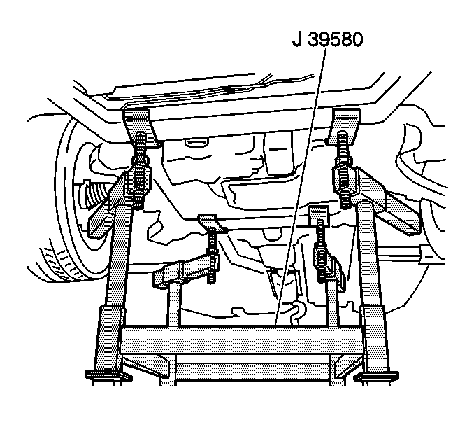
- Lower the vehicle until the frame contacts the transaxle table.
- Remove the frame bolts. Refer to Front Frame Replacement in Frame and Underbody.
- Raise the vehicle in order to separate the powertrain/frame assembly from the vehicle.
- Remove the starter motor. Refer to Starter Motor Replacement in Engine Electrical.
- Remove the torque converter covers. Refer to Torque Converter Cover Replacement in Automatic Transaxle - 4T40-E/4T45-E.
- Remove the torque converter bolts. Refer to Flywheel to Torque Converter Bolt Replacement in Automatic Transaxle - 4T40-E/4T45-E.
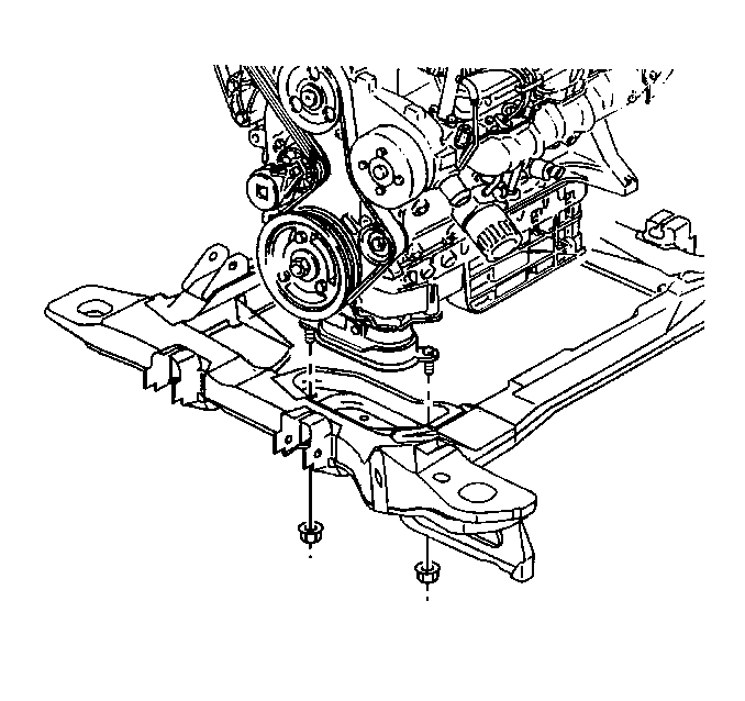
- Remove the engine mount lower nuts.
- Remove the transaxle brace. Refer to Transmission Brace Replacement in Automatic Transaxle - 4T40-E/4T45-E.
- Remove the exhaust crossover pipe. Refer to Exhaust Crossover Pipe Replacement in Engine Exhaust.
- Install engine hoist to engine.
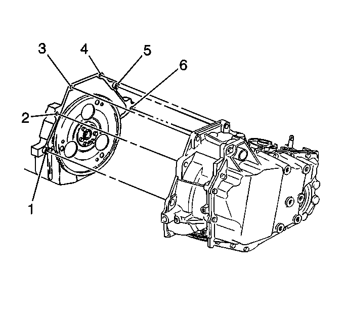
- Remove the transaxle-to-engine bolts (3, 4, 5, 6) and the studs (1, 2).
- Support the transaxle.
- Separate and remove the engine from the transaxle/frame.
- Install the engine to the engine stand.
- Remove the flywheel. Refer to Engine Flywheel Replacement .
- Remove the drive belt. Refer to Drive Belt Replacement .

| • | The knock sensor (KS) |
| • | The camshaft position (CMP) sensor |
| • | The crankshaft position (CKP) sensor |
| • | The heated oxygen sensor (HO2S) |
| • | The manifold absolute pressure (MAP) sensor |
| • | The exhaust gas recirculation (EGR) valve |
| • | The evaporative emission (EVAP) canister purge solenoid |
| • | The electronic throttle control |
| • | The ignition coil |
| • | The body wiring harness-to-engine harness |
| • | The engine wiring harness from transmission |
Caution: Failure to disconnect the intermediate shaft from the rack and pinion steering gear stub shaft can result in damage to the steering gear and/or intermediate shaft. This damage may cause loss of steering control which could result in an accident and possible personal injury


Installation Procedure
- Install the drive belt. Refer to Drive Belt Replacement .
- Install the flywheel. Refer to Engine Flywheel Replacement .
- Remove the engine from the engine stand.
- Install and align the engine to the transaxle/frame.
- Install the transaxle-to-engine bolts (3, 4, 5, 6) and the studs (1, 2).
- Remove the engine hoist from the engine.
- Install the exhaust crossover pipe. Refer to Exhaust Crossover Pipe Replacement in Engine Exhaust.
- Install the transaxle brace. Refer to Transmission Brace Replacement in Automatic Transaxle - 4T40-E/4T45-E.
- Install the engine mount lower nuts.
- Install the torque converter bolts. Refer to Flywheel to Torque Converter Bolt Replacement in Automatic Transaxle - 4T40-E/4T45-E.
- Install the torque converter covers. Refer to Torque Converter Cover Replacement in Automatic Transaxle - 4T40-E/4T45-E.
- Install the starter motor. Refer to Starter Motor Replacement in Engine Electrical.
- Position the transaxle table with the powertrain/frame under the vehicle.
- Lower the vehicle until the frame contacts the transaxle table.
- Install the new frame bolts. Refer to Front Frame Replacement in Frame and Underbody.
- Raise and support the vehicle. Refer to Lifting and Jacking the Vehicle in General Information.
- Remove the transaxle table.
- Install the intermediate shaft pinch bolt to the steering gear. Refer to Intermediate Steering Shaft Replacement in Steering Wheel and Column.
- Connect the drive axles to the transaxle. Refer to Front Wheel Drive Shaft Replacement in Wheel Drive Shafts.
- Position compressor to the engine and Install the A/C compressor bolts. Refer to Air Conditioning Compressor Replacement in Heating, Ventilation, and Air Conditioning.
- Install the lower ball joints to the knuckles. Refer to Lower Control Arm Ball Joint Replacement in Front Suspension.
- Install the tie rod ends to the steering knuckles. Refer to Steering Knuckle Replacement in Front Suspension.
- Install the stabilizer shaft links to the lower control arms. Refer to Stabilizer Shaft Link Replacement in Front Suspension.
- Install the engine splash shields. Refer to Engine Splash Shield Replacement in Body Front End.
- Install the lower radiator air baffle assembly. Refer to Radiator Air Baffle Assemblies and Deflectors in Engine Cooling.
- Install the front tires and wheels. Refer to Tire and Wheel Removal and Installation in Tires and Wheels.
- Install the catalytic converter. Refer to Catalytic Converter Replacement in Engine Exhaust.
- Install rear propeller shaft. Refer to Propeller Shaft Replacement in Propeller Shaft. (AWD Only)
- Lower the vehicle.
- Fill the crankcase with engine oil. Refer to Engine Oil and Oil Filter Replacement .
- Install the engine mount strut. Refer to Engine Mount Strut Replacement - Left Side and Engine Mount Strut Replacement - Right Side .
- Connect the following electrical connectors:
- Install the engine wiring harness ground nut to the transaxle stud.
- Install the fuel lines to the fuel rail. Refer to Fuel Injection Fuel Rail Assembly Replacement in Engine Controls - 3.5L.
- Install the brake booster vacuum hose to the upper intake manifold.
- Install the vacuum hoses to the upper intake manifold.
- Install the heater outlet and inlet hoses to the engine. Refer to Heater Inlet Hose/Pipe and Heater Outlet Hose/Pipe Replacement in Heating Ventilation and Air Conditioning.
- Install the radiator outlet hose to the engine. Refer to Radiator Outlet Hose Replacement in Engine Cooling.
- Install the radiator inlet hose to the engine. Refer to Radiator Inlet Hose Replacement in Engine Cooling.
- Install the air cleaner intake duct to the air cleaner housing (2) and the throttle body.
- Tighten the 2 intake air duct clamps (1).
- Connect the negative battery cable. Refer to Battery Negative Cable Disconnection and Connection in Engine Electrical.
- Fill cooling system. Refer to Cooling System Draining and Filling in Engine Cooling.
- Perform a CKP system variation learn procedure. Refer to Crankshaft Position System Variation Learn in Engine Controls - 3.5L.
- Inspect for leaks.
Notice: Refer to Fastener Notice in the Preface section.

Tighten
Tighten the bolts (3, 4, 5, 6) and the studs (1, 2) to 75 N·m (55 lb ft).

Tighten
Tighten the nuts to 43 N·m (32 lb ft).

Caution: Failure to disconnect the intermediate shaft from the rack and pinion steering gear stub shaft can result in damage to the steering gear and/or intermediate shaft. This damage may cause loss of steering control which could result in an accident and possible personal injury
| • | The KS |
| • | The CMP sensor |
| • | The CKP sensor |
| • | The HO2S |
| • | The MAP sensor |
| • | The EGR valve |
| • | The EVAP canister purge solenoid |
| • | The electronic throttle control |
| • | The ignition coil |
| • | The body wiring harness-to-engine harness |
| • | The engine wiring harness from transmission |
Tighten
Tighten the nut to 35 N·m (26 lb ft).

Tighten
Tighten the clamps to 2 N·m (18 lb in).
