For 1990-2009 cars only
Removal Procedure
Caution: Never attempt to remove the intake manifold from a hot engine, allow the engine to cool to ambient temperature. The intake manifold is made of a composite plastic and can be damaged if it is removed when the engine is hot.
- Remove the intake manifold cover. Refer to Intake Manifold Cover Replacement.
- Remove the oil level indicator tube. Refer to Oil Level Indicator and Tube Replacement.
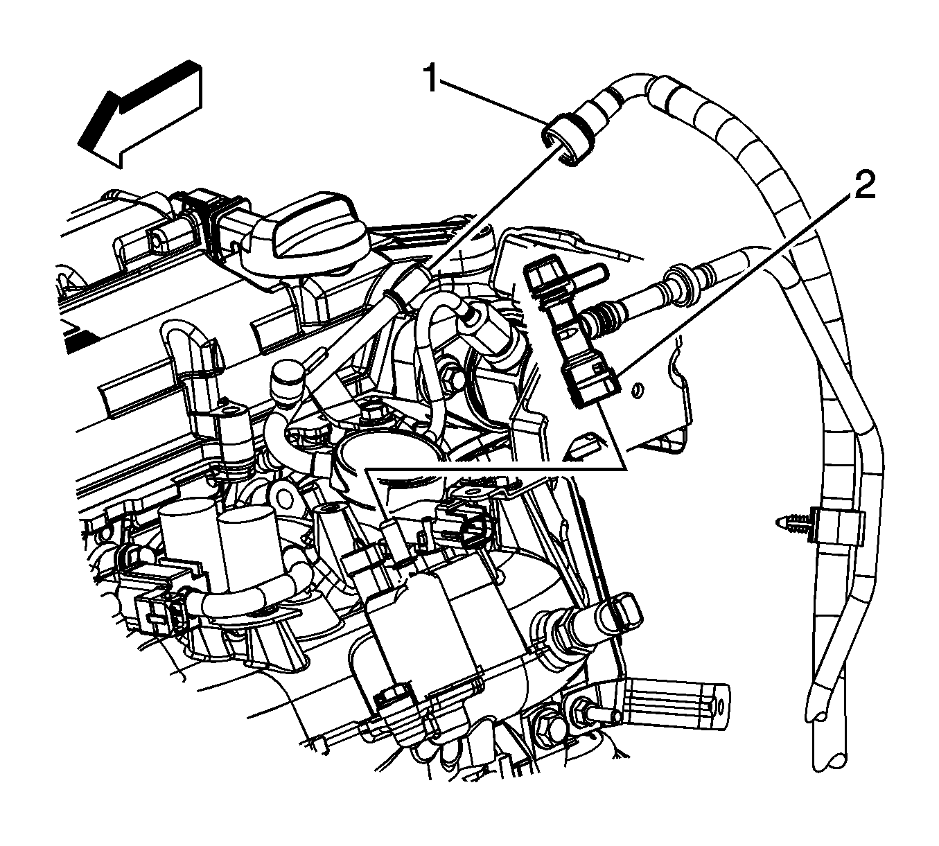
- Disconnect the fuel feed line quick connect fitting (1) from the fuel rail. Refer to Metal Collar Quick Connect Fitting Service.
- Disconnect the evaporative emission (EVAP) line quick connect fitting (2) from the EVAP purge solenoid. Refer to Plastic Collar Quick Connect Fitting Service.
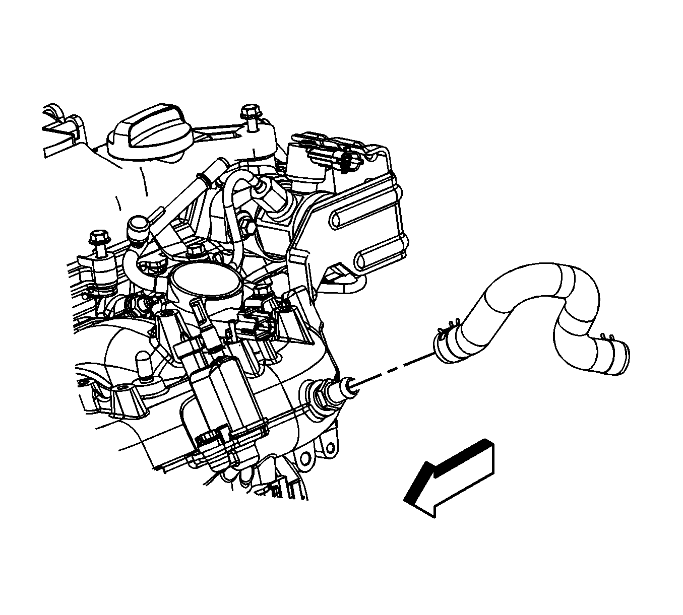
- Reposition the brake booster vacuum hose clamp at the intake manifold.
- Remove the brake booster hose from the intake manifold.
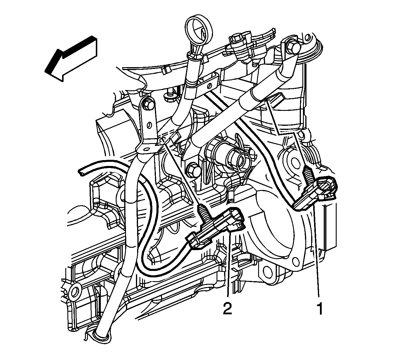
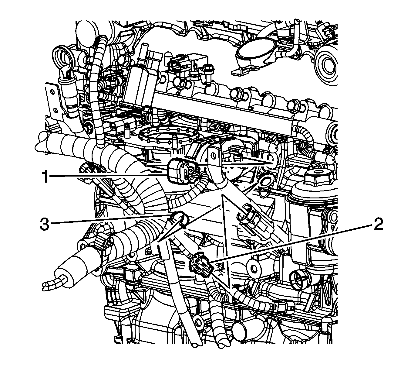
- Remove the knock sensor electrical connector (1) clip from the intake manifold brace.
- Remove the knock sensor electrical connector (2) clip from the oil level indicator tube bracket.
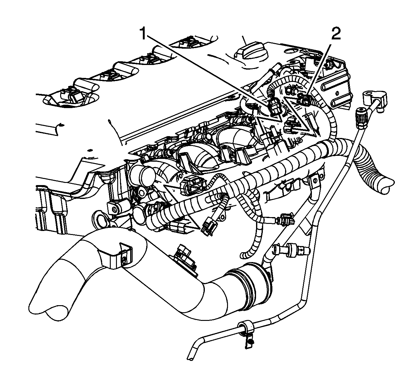
- Disconnect the engine wiring harness electrical connector (1) from the EVAP canister purge solenoid.
- Disconnect the engine wiring harness electrical connector (2) from the manifold absolute pressure (MAP) sensor.
- Disconnect the engine wiring harness electrical connector from the charge air bypass vale solenoid.
- Disconnect the engine wiring harness electrical connector (1) from the throttle actuator control (TAC) module.
- Remove the engine wiring harness clip (3) from the intake manifold brace.
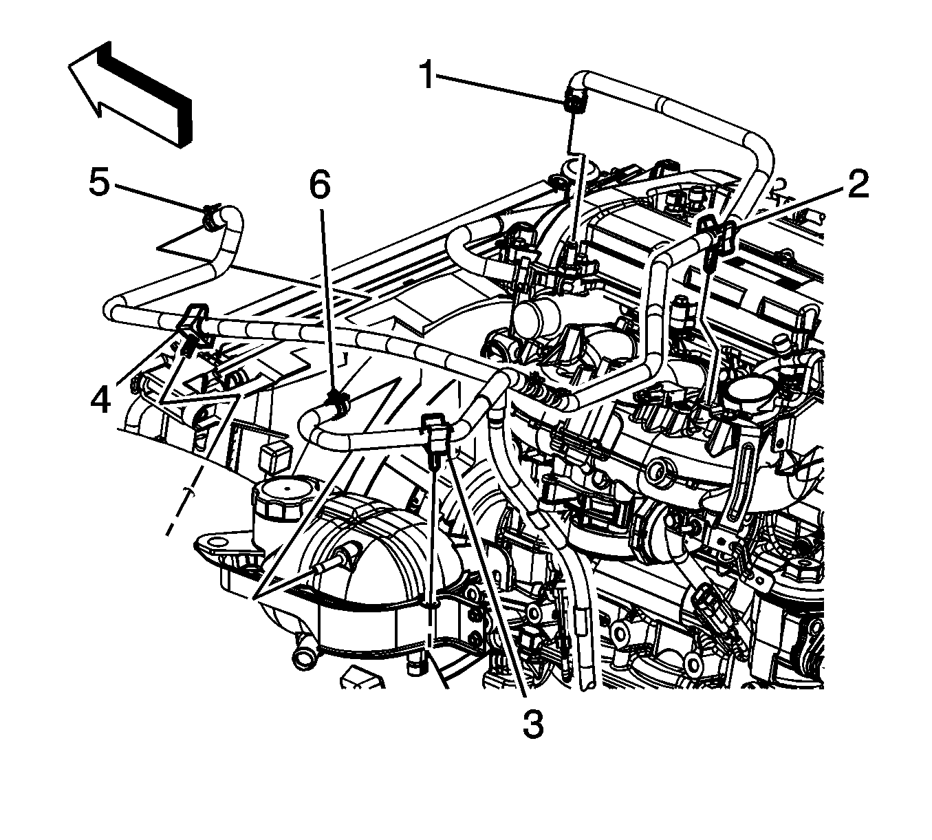
- Reposition the surge tank air bleed hose clamp at the engine (1).
- Remove the surge tank air bleed hose from the engine.
- Remove the surge tank air bleed hose clip (2) from the surge tank bracket.
- Reposition the surge tank air bleed hose out of the way.
- Reposition the charge air bypass valve vacuum hose clamp at the intake manifold.
- Remove the charge air bypass valve vacuum hose from the intake manifold.
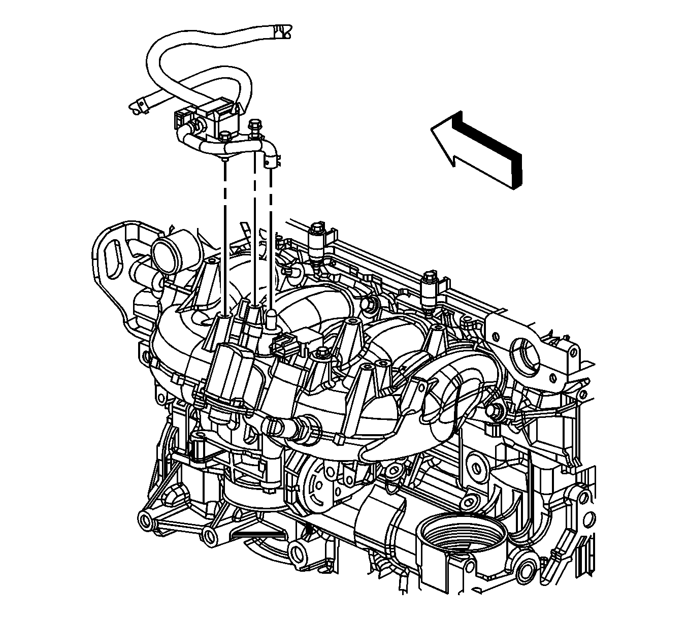
- Remove the charge air bypass valve solenoid bolts.
- Reposition the charge air bypass valve solenoid assembly out of the way.
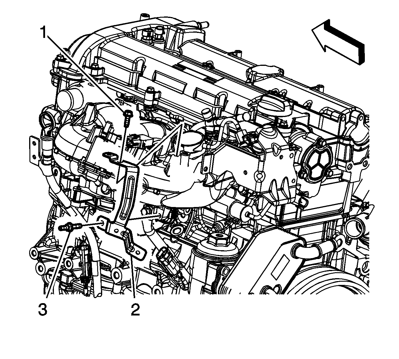
- Remove the surge tank bracket bolt (1) and stud (2).
- Remove the surge tank bracket (3).
- Remove the surge tank hose retainer and hose from the surge tank bracket.
- Disconnect the metal quick connect fitting from the fuel feed pip. Refer to Metal Collar Quick Connect Fitting Service.
- Disconnect the fuel feed pipe fitting from the fuel pump.
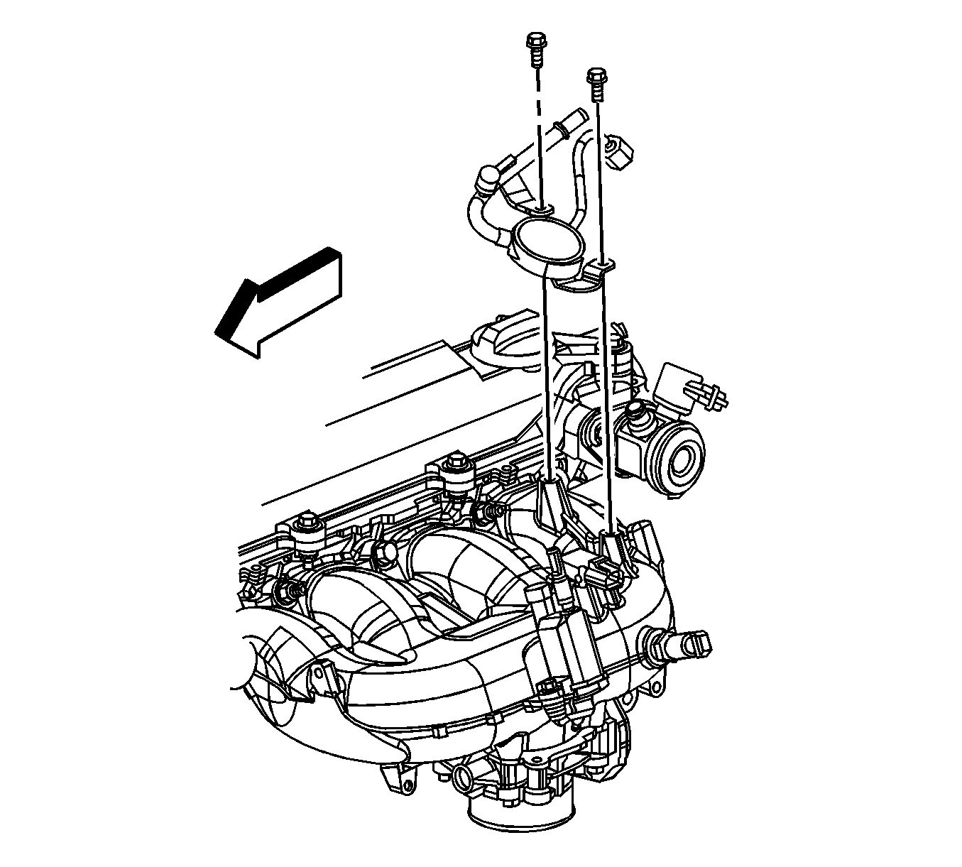
- Remove the fuel feed pipe bolts.
- Remove the fuel feed pipe.
- Inspect the fuel feed pipe nut for damaged threads.
- Inspect the fuel feed pipe sealing bail for damage or debris.
- Replace the fuel feed pipe if any damage is found.
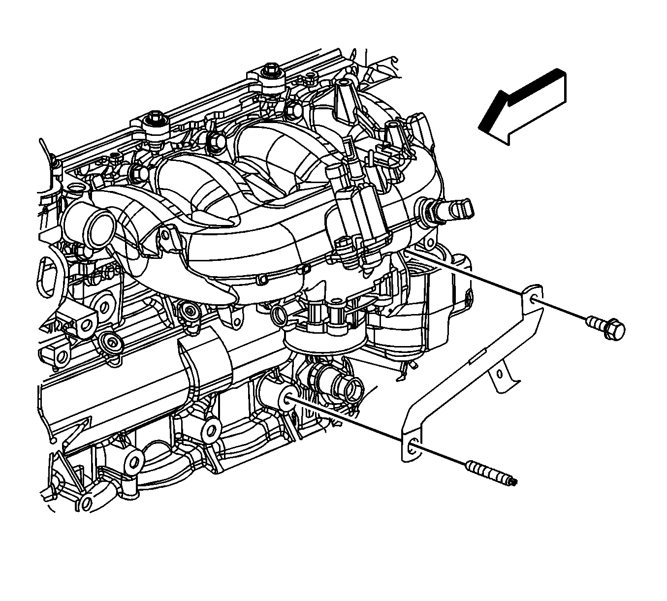
- Remove the intake manifold brace bolt.
- Remove the intake manifold brace.
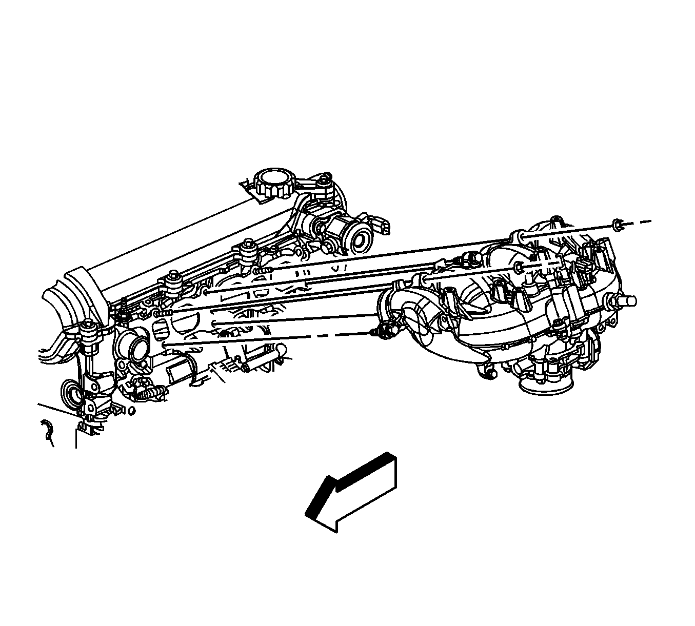
- Remove the intake manifold bolts and nuts.
- Remove the intake manifold and place on a clean work surface.
- Remove the intake manifold gasket, if necessary.
- If replacing the intake manifold perform the following steps, otherwise proceed to step 11 in the installation procedure.
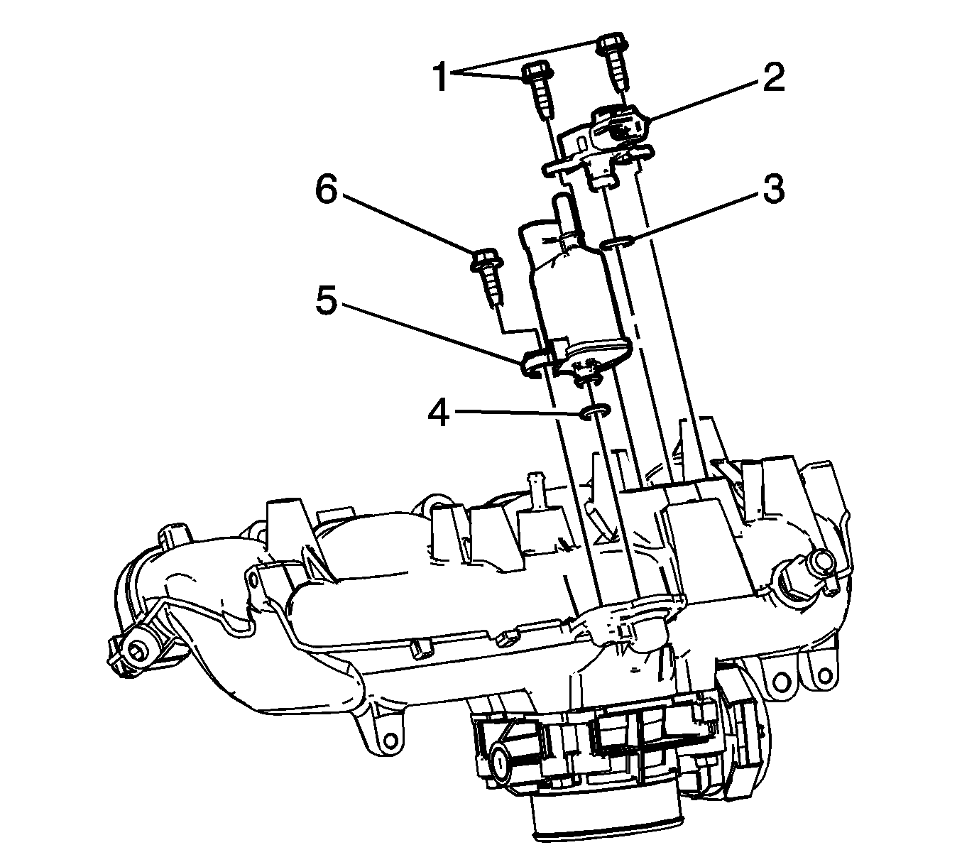
- Remove the MAP sensor bolts (1).
- Remove the MAP sensor (2), ensure that the O-ring seal (3) is still attached on the sensor, if not remove the O-ring seal from the intake manifold.
- Remove the EVAP purge solenoid bolt (6).
- Remove the EVAP purge solenoid (5), ensure that the O-ring seal (4) is still attached on the sensor, if not remove the O-ring seal from the intake manifold.
- Turn the intake manifold up side down.
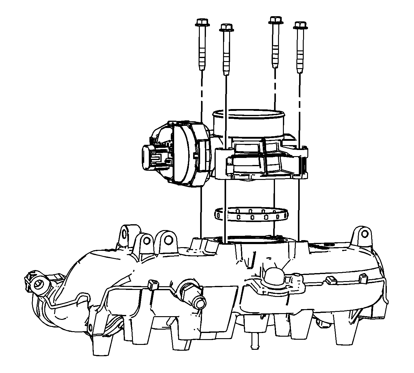
- Remove the throttle body bolts.
- Remove the throttle body and seal.
Note: The intake manifold gasket is reusable. Only replace the gasket if damage has occurred.
Installation Procedure
- If replacing the intake manifold perform the following steps, otherwise proceed to step 11.
- Inspect the throttle body seal and replace if necessary.
- Install the throttle body seal and position the throttle body.
- Install the throttle body bolts.
- Turn the intake manifold right side up.
- Inspect the EVAP purge solenoid and MAP sensor O-ring seals, replace if necessary.
- Ensure that the EVAP purge solenoid O-ring seal (4) is installed on the EVAP purge solenoid (5).
- Install the EVAP purge solenoid (5) and bolt (6).
- Ensure that the MAP sensor O-ring seal (3) is installed on the MAP sensor (2).
- Install the MAP sensor (2) and bolts (1).
- Install the intake manifold gasket, if necessary.
- Install the intake manifold to the studs.
- Install the intake manifold bolts and nuts.
- Install the intake manifold brace.
- Loosely install the intake manifold brace bolt.
- Tighten the intake manifold brace bolt.
- Lubricate the high pressure fuel pump fuel feed pipe connection threads with silicon free engine oil GM P/N 12345610 (Canadian P/N 993193) or equivalent.
- Place the fuel feed pipe on top of the intake manifold.
- Connect the fuel feed pipe fitting to the high pressure fuel pump.
- Install the fuel feed pipe bolts.
- Connect the metal quick connect fitting to the fuel feed pip. Refer to Metal Collar Quick Connect Fitting Service.
- Position the surge tank bracket (3) to the intake manifold.
- Install the surge tank bracket bolt (1) and stud (2).
- Install the surge tank hose retainer and hose to the surge tank bracket.
- Position the charge air bypass valve solenoid assembly to the intake manifold.
- Install the charge air bypass valve solenoid bolts.
- Install the charge air bypass valve vacuum hose to the intake manifold.
- Position the charge air bypass valve vacuum hose clamp at the intake manifold.
- Position the surge tank air bleed hose to the engine.
- Install the surge tank air bleed hose to the engine.
- Position the surge tank air bleed hose clamp at the engine (1).
- Install the surge tank air bleed hose clip (2) to the surge tank bracket.
- Connect the engine wiring harness electrical connector (1) to the TAC module.
- Install the engine wiring harness clip (3) to the intake manifold brace.
- Connect the engine wiring harness electrical connector to the charge air bypass vale solenoid.
- Connect the engine wiring harness electrical connector (2) to the MAP sensor.
- Connect the engine wiring harness electrical connector (1) to the EVAP canister purge solenoid.
- Install the knock sensor electrical connector (1) clip to the intake manifold brace.
- Install the knock sensor electrical connector (2) clip to the oil level indicator tube bracket.
- Install the brake booster hose to the intake manifold.
- Position the brake booster vacuum hose clamp at the intake manifold.
- Connect the EVAP line quick connect fitting (2) to the EVAP purge solenoid. Refer to Plastic Collar Quick Connect Fitting Service.
- Connect the fuel feed line quick connect fitting (1) from the fuel rail. Refer to Metal Collar Quick Connect Fitting Service.
- Install the oil level indicator tube. Refer to Oil Level Indicator and Tube Replacement.
- Install the intake manifold cover. Refer to Intake Manifold Cover Replacement.

Caution: Refer to Fastener Caution in the Preface section.
Tighten
Tighten the bolts to 10 N·m (89 lb in).

Tighten
Tighten the bolt to 10 N·m (89 lb in).
Tighten
Tighten the bolts to 10 N·m (89 lb in).

Tighten
Tighten the bolts/nuts to 22 N·m (16 lb ft).

Tighten
Tighten the bolt to 22 N·m (16 lb ft).

Tighten
| • | Tighten the bolts to 10 N·m (89 lb in). |
| • | Tighten the fitting to 30 N·m (22 lb ft). |

Tighten
Tighten the bolt/stud to 9 N·m (80 lb in).

Tighten
Tighten the bolts to 10 N·m (89 lb in).


